


6-43
Reassembling Notes
• When placing the air pump & motor module onto the ink cartridge support base, make sure that
the air tube (blue) is not bent.
• When setting the cover spring into place, take care not to pull it out of shape by extending it too
much.
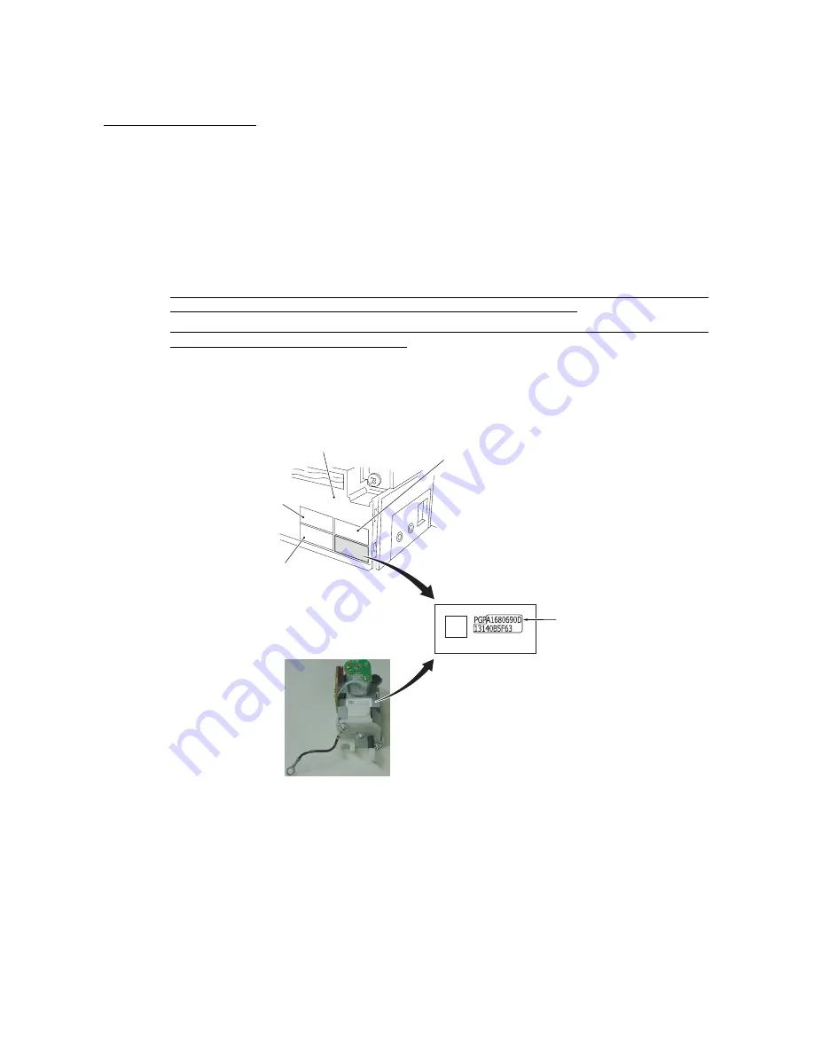
• Like the print head unit, each air pump & motor module is assigned a property code that
represents the properties unique to that module. A property label, on which a property code is
printed, is attached to the module itself and to the rear left side of the machine (with the battery
cover* or rear cover S** removed). (*For the MFC4820C, **For the MFC4420C. Refer to
Section 6.1.4.)
If you remove the air pump & motor module and store it separately from the machine, remove
the property label from the machine and store it together with the module.
If you replace the module with a new one, attach the property label that comes with the new
module to the rear left side of the machine.
If the module is replaced with a new one, you will need to update the property data stored in the
EEPROM on the driver PCB. Make the machine enter the maintenance mode (Function code 68
+ 0789) and enter the 19 digits of the property code of the newly installed module. (For details,
refer to Chapter 7, Section 7.5.15.)
Property code
(19-digit)
Lower cover
(Rear)
For paper feed roller
For ejection roller
For print head unit
Property label for
air pump & motor module
• When you replace the ink absober box with out replaceing the driver PCB, reset the purge count
according to the following procedure.
1) Press the [Menu], [2],[8],[6]and [4] keys in this order to make the machine enter the
maintenance mode.
2) Press the [8] and [0] keys in this order. to show the equipment’s log information on LCD.
3) Press the [Fax Start] button nine times. to show the purge count on LCD.
4) Press the [2],[7],[8] and [3] keys. to reset the purge count.
5) Press the [9] key twice in the initial stage of the maintenance mode to restore the machine to the
standby state.
Summary of Contents for MFC-4820C
Page 1: ...FACSIMILE EQUIPMENT SERVICE MANUAL MODEL MFC4820C MFC4420C ...
Page 6: ...CHAPTER 1 PARTS NAMES FUNCTIONS ...
Page 13: ...CHAPTER 2 SPECIFICATIONS ...
Page 19: ...2 5 2 1 4 Environmental Conditions ...
Page 26: ...CHAPTER 3 SETTING UP OF THE MACHINE ...
Page 29: ...3 2 3 2 UNPACKING THE MACHINE The equipment consists of the following major components ...
Page 40: ...CHAPTER 4 THEORY OF OPERATION ...
Page 76: ...CHAPTER 5 ROUTINE MAINTENANCE ...
Page 84: ...CHAPTER 6 DISASSEMBLY REASSEMBLY ...
Page 114: ...6 29 6 1 11 Speaker 1 Pull the speaker and its spring out of the lower cover ...
Page 136: ...CHAPTER 7 MAINTENANCE MODE ...
Page 145: ...7 8 Scanning Compensation Data List ...
Page 160: ...7 23 1st sheet 2nd sheet Vertical Alignment Check Patterns and Head Skew Check Pattern ...
Page 162: ...7 25 Margin Check Patterns ...
Page 170: ...CHAPTER 8 ERROR INDICATION AND TROUBLESHOOTING ...
Page 197: ...MFC4820C MFC4420C Appendix 1 Serial No Descriptions ...
Page 205: ...App 2 4 Click Finish to return to Windows ...
Page 209: ...MFC4820C MFC4420C Appendix 3 EEPROM Customizing Codes ...
Page 212: ...MFC4820C MFC4420C Appendix 4 Firmware Switches WSW ...
Page 252: ...App 4 40 WSW48 to WSW50 Selector No Function Setting and Specifications 1 8 Not used ...
Page 253: ...MFC4820C MFC4420C Appendix 5 Re Packing Instructions ...
Page 255: ...App 5 2 2 Place the machine in the original box with the original packaging material ...
Page 256: ...MFC4820C MFC4420C Appendix 6 Wiring Diagram ...
Page 259: ...A Main PCB 1 5 ...
Page 260: ...A Main PCB 2 5 ...
Page 261: ...A Main PCB 3 5 ...
Page 262: ...A Main PCB 4 5 ...
Page 263: ...A Main PCB 5 5 ...
Page 264: ...B Driver PCB ...
Page 265: ...C NCU PCB ...
Page 266: ...D Control Panel PCB ...
Page 267: ...E Power Supply PCB ...


