background image

I - 5

(b) Special paper (specified types)

•  Labels
•  Envelopes (DL, C5, COM10)
•  Postcards
•  Organizers (K, L, and M sizes of DAY-TIMERS)

(2) Paper feed conditions

2.7

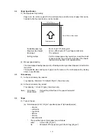
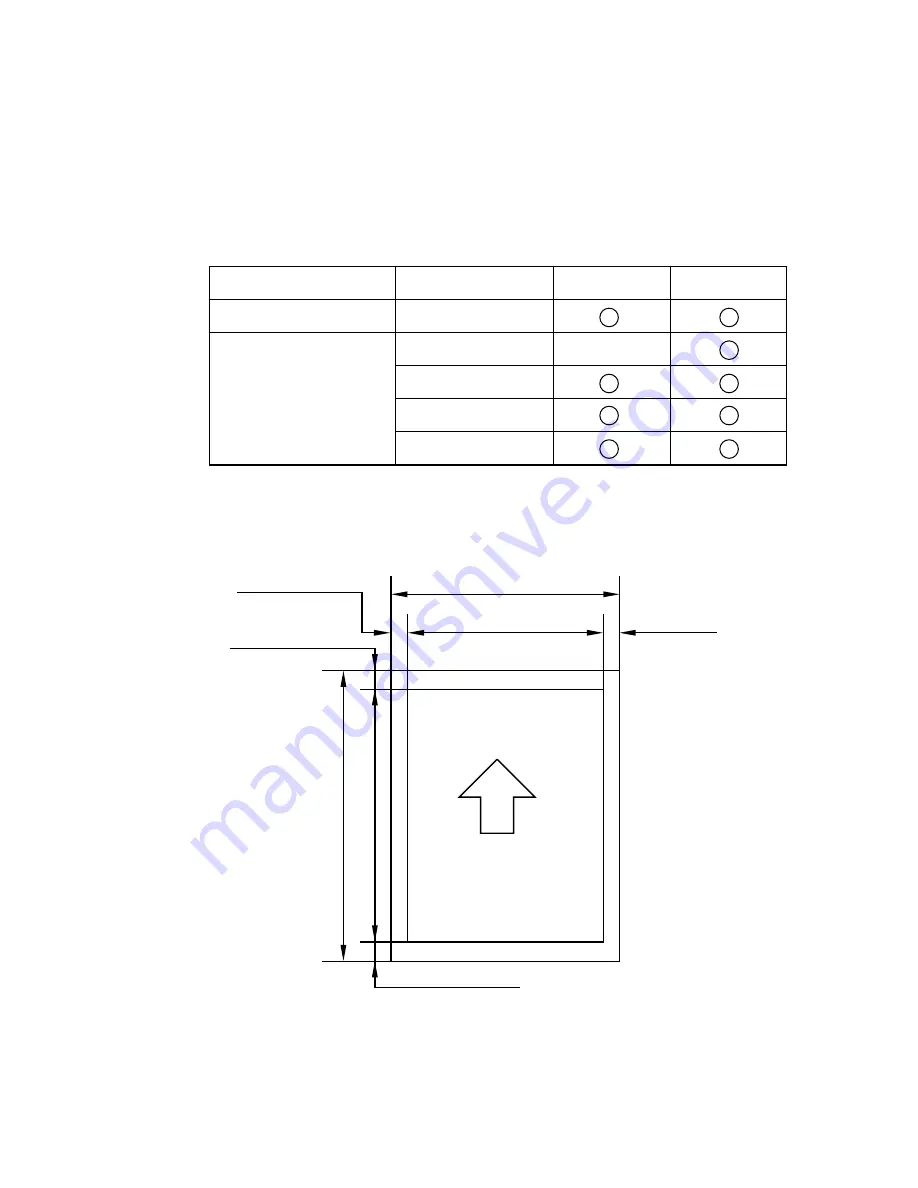
Effective printing area

Printable area

The effective printing area means the area within which the printing of all the data received without
any omissions can be guaranteed.

A

D

B

F

F

E

E

C

Type

Name

Tray feed

Manual feed

Normal paper (cut sheet)

Special paper (cut sheet)

60 to 135 g/m

2

 paper

Labels

Envelopes

Postcards

Organizers

Summary of Contents for HL-600 Series

Page 1: ...MECHANICS ELECTRONICS SERVICE MANUAL LASER PRINTER ...

Page 2: ...tem the electrical system and the electrical circuit and their timing CHAPTER III DISASSEMBLY AND REASSEMBLY Procedures of disassembling and reassembling the mechanical system CHAPTER IV TROUBLESHOOTING Reference values and adjustment troubleshooting for image defects troubleshooting for malfunctions etc Information in this manual is subject to change due to improvement or re design of the product...

Page 3: ...I O II 8 1 3 7 EFPROM II 9 1 3 8 Reset Circuit II 9 1 3 9 CDCC I O II 9 1 3 10 Engine I O II 10 1 4 Driver PCB II 11 1 4 1 Paper Feed Motor Drive Circuit II 11 1 4 2 Solenoid Pick up Clutch Erase Lamp Fan Motor Drive Circuit II 11 1 4 3 Operation Panel II 12 1 4 4 Scanner Motor Laser Sensors Registration Paper Eject Toner Thermistor High voltage Power Supply II 12 1 5 Power Supply II 13 2 MECHANIC...

Page 4: ...III 8 3 11 Registration Sensor PCB III 8 3 12 Solenoid P III 9 3 13 Gear Shaft Plate III 9 3 14 Gears III 10 3 15 Main Motor Unit III 11 3 16 Solenoid C III 11 3 17 Main PCB III 12 3 18 Base Plate III 12 3 19 Driver PCB III 14 3 20 Power Supply PCB III 14 3 21 High voltage Power Supply III 15 3 22 Tray Extention III 15 3 23 Paper Eject Tray III 16 3 24 Filter Cover III 16 4 PACKING III 17 CHAPTER ...

Page 5: ...XL When you use DOS application software or WindowsTM version 3 0 or earlier you can use any of these emulationstooperatetheprinter TheprinteralsosupportsAuto emulation switching between HP and Epson or HP and IBM If you want to fix the printer emulation you can do it using the Remote Printer Console Program Bi Directional Parallel Interface The parallel interface of this printer allows bi directi...

Page 6: ...Functions CPU MC68EC000 16 MHz Emulation AutomaticemulationselectionamongHPLaserJetIIP EPSON FX 850 and IBM Proprinter XL Printer Driver WindowsTM 3 1driver supportingBrotherNativeCompression mode and bi directional capability Optional Macintosh QuickDraw driver Standard in some countries Interface Bi directional Centronics parallel RS 422A RS 232C serial interface is optionally available The seri...

Page 7: ... 5 C 59 to 90 5 F Storage 0 to 40 C 38 to 104 F Humidity Operating 20 to 80 without condensation Storage 20 to 80 without condensation Dimensions W x H x D 357 W 351 D 192 H mm when the output tray is closed and the Multi purpose sheet ...

Page 8: ...and a single sheet of paper can be fed into the printer The applicable sizes and types of paper are the same as the multi purpose tray loading above in specification 2 5 Print delivery 1 At the print delivery tray opened Tray capacity Maximum 100 sheets 75g m2 face down only 2 At the print delivery tray closed Tray capacity 1 sheet 75 g m2 face down only Note Face down Deliver the printed face of ...

Page 9: ...tions 2 7 Effective printing area Printable area The effective printing area means the area within which the printing of all the data received without any omissions can be guaranteed A D B F F E E C Type Name Tray feed Manual feed Normal paper cut sheet Special paper cut sheet 60 to 135 g m2 paper Labels Envelopes Postcards Organizers ...

Page 10: ...m 8 5 2 550 dots 355 6mm 14 0 4 200 dots 207 5mm 8 0 2 400 dots 288 5mm 10 67 3 200 dots 182 0 mm 257 0 mm 173 5 mm 248 5 mm 184 15mm 7 25 2 175 dots 266 7mm 10 5 3 150 dots 175 7mm 6 92 2 400 dots 258 2mm 10 17 3 200 dots 148 5mm 1 754 dots 105 0mm 1 240 dots 1 654 dots 1 140 dots 95 25mm 3 75 1 125 dots 171 45mm 6 75 2 025 dots 86 78mm 3 42 1 025 dots 162 98mm 6 42 1 925 dots 139 7mm 5 5 1 650 d...

Page 11: ...beamcannotescapefromthemachineduringanyphaseofuseroperation 3 2 CDRH Regulations 110 120 V Model only The Center for Device and Radiological Health CDRH of the US Food and Drug Administration implemented regulations for laser products on August 2 1976 These regulations apply to laser products manufactured from August 1 1976 Compliance is mandatory for products marketed in the United States The lab...

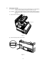
Page 12: ...2 CAUTION In case of any trouble with the laser unit please replace the laser unit itself To prevent direct exposure to the laser beam do not try to open the enclosure of laser unit 3 Location of the Exit Opening of Laser Beam Fig 1 3 CLASS 1 LASER PRODUCT APPAREIL A LASER DE CLASSE 1 LASER KLASSE 1 NACH IEC825 UH0741 4 Location of Caution Label for Laser Product Fig 1 2 Scanner unit ...

Page 13: ...ock Interface block External device Engine control block High voltage power supply block Image generation system Drive block Stepping motor Laser scanner unit Paper tray unit Manual feed Paper tray Fixing unit Paper feed system Drum unit Transfer block Developing block Cleaner block Charging block Drum Toner cartridge Fig 2 1 General Block Diagram External device Eraser lamp Paper eject block Oper...

Page 14: ... ROM 512 KByte RAM 0 5M or 1M Byte OPTION RAM 0 5M or 1M Byte OPTION SERIAL I O RS232C RS422A EEPROM 128 8 bit CPU MC68EC000 A S I C OSCILLATOR 15 3MHz ADDRESS DECODER DRAM CONTROL TIMER FIFO CDCC PARALLEL I O SOFT SUPPORT EEPROM I O ENGINE CONTROL I O TO DRIVER PCB BUS INT Fig 2 2 Main PCB Block Diagram ...

Page 15: ...N16 NC 22 RESET 21 20 16 11 NC RESET HALT CLK DTACK BR BERR AVEC IPL0 IPL1 IPL2 IPL0 IPL1 IPL2 27 26 25 AVEC 5V SCLK DTACK BR 13 24 23 VCC VCC VCC CND CND CND CND CND BC 14 15 53 14 14 1 17 18 35 57 0V 12 30 29 28 19 7 10 8 9 FC0 FC1 FC2 MODE A0 NC AS R W UDS LDS AS R W UDS LDS FC0 FC1 FC2 BC 5V 04C 05F 05F 05F 04C 04C 04C 04C 6 05F 05E 05 05F 05F 05F 05F 05F 1 3 Main PCB 1 3 1 CPU The CPU is a Mo...

Page 16: ...2 CDCC Low 1 Timer2 5 Timers The following timers are incorporated Timer 1 16 bit timer Timer 2 10 bit timer Timer 3 Watch dog timer 1 Timer 4 Watch dog timer 2 6 FIFO A2 560 bitFIFOisincorporated DataforonerasteristransferedfromtheRAM to the FIFO by DMA transmission and is out put as serial video data The data cycle is 1 53 MHz 7 CDCC parallel I O CDCC data is received in 4 byte units by DMA tran...

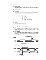
Page 17: ... switched to the HIGH SPEED MODE It is also possible to fix the mode to the LOW SPEED MODE by sending a command from the PC to rewrite the contents of the NV RAM BUSY goes HIGH at the falling edge of STROBE The data 8 bit from the PC is latched in the ASIC at the rising edge of STROBE The pulse width of ACK differs according to the MODE as shown above 8 Software support Supports16x16rotation bitex...

Page 18: ...7 XIN 02 07D DCI 8 1 02 07C SELIN HBUSY PRMINT STB SW1 SW2 HAISI LOCK TONER SENSE XVDO 02 07C 02 07C 02 07C C40 101 01F 01F 01F IPL0 02F 02F 02F FC0 FC1 FC2 IPL1 IPL2 AVEC 01E FC0 FC1 FC2 IPL0 IPL1 IPL2 AVEC SCLK BR BGACK DTACK RD ROM1 ROM0 ROM0 SCL RD DTACK BR SCLK 01E 01E 11F 01E 72 73 21 125 127 128 129 131 134 133 132 137 136 135 R19 100 11F 01B 71 67 66 55 54 52 53 51 37 35 50 49 48 47 68 45 ...

Page 19: ...5V 04 RD ROM0 11 13 32 CE OE BYTE 1 UPD27C8000CZ VCC CND CND 31 12 14 C26 104 5V 0V MA0 MA1 MA2 MA3 MA4 MA5 MA6 MA7 MA8 MA9 16 17 18 19 22 23 24 25 26 15 A1 A2 A3 A4 A5 A6 A7 A8 A9 A0 DQ1 DQ2 DQ3 DQ4 DQ5 DQ6 DQ7 DQ8 DQ9 DQ10 DQ11 DQ12 DQ13 DQ14 DQ15 DQ16 2 3 4 5 7 8 9 10 D1 D2 D3 D4 D5 D6 D8 D9 D10 D11 D12 D13 D14 D0 D7 D15 31 32 33 34 36 37 38 39 NC NC NC NC 11 NC 29 NC 30 27 13 12 28 14 OE UW CA...

Page 20: ... 11 12 13 14 15 D1 D2 D3 D4 D5 D6 D7 D0 D9 D10 D11 D12 D13 D14 D15 D8 25 24 20 19 18 17 16 26 DQ9 DQ10 DQ11 DQ12 DQ13 DQ14 DQ15 DQ16 VCC VSS 23 4 3 21 22 2 1 VCC VCC VSS VSS VSS C25 104 5V 0V 01 07H D 15 0 01 09C MA 9 0 01 05C ICAS1 R18 0 P3 OPTION I F RESET OPCS RD WR A5 RESET 01 01E OPTION 01 05C RD WR 01 11F 01 05B A4 A3 A2 A1 D7 D6 D5 D4 D3 D2 D1 D0 OPIRQ SENTAN BD EXVDO LEDR SENSE 5V 5V 5V 0V...

Page 21: ...K 01 05B BUSY 01 05B PE 01 05B SLCT 01 05B FLT 01 05B PRMINT 01 04A SELIN 01 04A HBUSY 01 04A STB 01 04A DC18 DC17 DC16 DC15 DC14 DC13 DC12 DC11 DCI 8 1 01 03C C45 C44 C43 C38 C36 C41 0V C47 C42 C54 C49 101 X12 C50 C39 RAS 100 1 2 6 5 1 7 6 5 8 7 3 4 8 2 3 4 RA3 100 4 7 3 8 5 2 6 1 100 RA1 5 7 3 8 7 8 6 5 7 8 6 5 4 3 1 2 4 3 1 2 1 6 2 4 RA2 1K 1K 1K RA4 RA6 5V P4 CDCC 10 11 12 13 32 31 36 14 1 ACK...

Page 22: ...02 C12 102 04A 04A SW1 SW2 02 04C 03B 04A TONER 5VI HAISI R4 R16 100 R14 C4 C24 C18 0V 100 100 102 X3 02 04C LEDR R31 R32 R30 R33 330 330 220 220 C8 C23 C16 C3 182 X4 0V R9 R5 R2 100K 5 1K 6 2K C17 104 R10 18K HCMPI 0V 04B TONERTH HEATTH 10C 0V C6 C20 C14 C19 C2 102 X4 C21 C15 C7 C22 C10 C11 102 101 X6 04B MCMP1N MCMP2N 04B R8 1K 1K R1 C13 102 C5 102 NC 1 2 3 6 5 4 NC 0V 0V DA1 RB731U Q10 DTC114YK...

Page 23: ...against overvoltage due to counter electromotive force Fig 2 15 R14 3 3K R15 3 3K R16 3 3K R17 3 3K 2SC5060 Q4 2SC5060 Q43 2SC5060 Q2 2SC5060 Q1 24VRET 24V D1NL20U DS 1 2 24V FAN P4 FAN 1 2 24V ERASE P10 ERASE 24VI P9 PICKUP CLUTCH RESIST 1 2 3 4 5 6 24V CLUTCH PICKUP 5V RESIST GND 1 4 2 Solenoid Pick up Clutch Erase Lamp Fan Motor Drive Circuit A darlington transistor 2SC5060 is used for these ci...

Page 24: ...olled directly from the main PCB the driver PCB has only relays the above signals of each connectors 24VRET 24VI 0V 5VI 1 2 3 4 5 1 2 3 4 5 VDO GND 5V LDON BD SCANCLK LOCK DRIVE GND 24V P6 LASER P7 SCANNER MOTER 1 2 3 4 5 6 24VRET 24VI TAIDEN GENZOU TENSHAH TENSHAL GND 24V P8 HIGH VOLTAGE 1 2 3 5 4 3 2 1 1 2 TONERTH THERMIN ANODE TONER GND HEATTH THERMIN ANODE HAISI GND P13 TONER THERMISTOR P12 TO...

Page 25: ...generate the regulated DC power 5V and 24V which are converted from the AC line Heater Circuit Thermal Fuse Lightning Surge Absorber Feedback Line Filter Fuse Rectifier Oscillator 24V Regulation Circuit 5V Regulation Circuit SW SW 24VI 24V 5VI 5V Lamp Heater Driver Circuit Fig 2 18 ...

Page 26: ...it Main Motor Fan Motor Registration Sensor Solenoid P Solenoid C Transfer Roller Process Unit Multi Purpose Tray Photosensitive Drum Fuser Unit Pressure Roller Polygon Mirror Cleaner Blade Primary Changer Scanner Unit Toner Cartridge Paper Pick Up Roller Paper Regist Roller Paper Supply Unit Manual Paper Pass Papers Hopper Plate Exit Roller Eject Sensor Actuator Developer Roller Toner Empty Senso...

Page 27: ... paper picked up from the multi paper tray MPT presses against the top of form sensor actuator the registration sensor lever is caused to turn and the photo sensor detects this motion With this signal from the sensor the registration roller is stopped of its rotation temporarily by the clutch Then paper is fed to the nip point between the registration roller and the pinch roller in the process uni...

Page 28: ...o sensor photo interrupter is opened and detects the start of paper eject motion b After that when the bottom of the edge of paper has passed through the paper eject sensor actuator the photo sensor is closed and the completion of paper eject motion is recognized Transfer roller Heat roller Eject sensor actuator Eject roller Fixing unit Presure roller Eject sensor actuator Sensor Paper Fig 2 22 ...

Page 29: ... 2 Cover Sensor Detects open or close of the top cover 2 3 3 Toner Empty Sensor Detects if there is toner in the toner cartridge It also detects whether or not the process unit is installed The toner cartridge is installed in the process unit Multi paper tray Top cover Cover switch lever MPT switch lever Fig 2 23 ...

Page 30: ...ischarges the electrostatic latent image on the drum 2 5 Print Process 2 5 1 Charging The drum is charged to appox 700V by ion which is generated by the primary charger Ion is generated by an ionization of the corona wire which applied DC bias from High Voltage Power Supply The flow of ion is controlled by the grid to be distributed evenly on the drum surface The other end of the grid is grounded ...

Page 31: ...ed area is decreated forming an electrostatic image to be printed Drum Paper Laser detector Laser diode Motor Laser beam f lens Polygon mirror Lens Laser Beam 1 Cycle of drum Surface Potential V 700 500 100 1 2 3 4 a b Time 1 2 3 4 Primary charging Laserbeam exposure and developing a Unexposed area Non image area b Exposed area Image area Transfer the image to paper Erase the residual potential Fi...

Page 32: ...to attract toner particles from the developer roller to the drum N N N N S S S S Carrier Toner Transfer Roller a Transfer process ON b Cleaning process ON Cleaning blade Erase lamp DC bias b Cleaning process of transfer roller If the toner is not transferred onto the paper perfectly due to jamming etc it is possible that the toner adheres to the charge transfer roller The transfer voltage charges ...

Page 33: ...face is removed away and collected in the cleaning housing In the cleaning housing collected toner is transported to the developer unit by the toner auger This toner is mixed with new toner and is used again at the developing stage 2 5 6 Erasing Stage After the cleaning stage the drum surface is exposed by the light emitted from the erase lamp LED lamp This stage prepares the drum to decrease its ...

Page 34: ...vers 5 Before handing the PCBs touch a metal portion of the equipment to discharge the static electricity charged in your body or the electronic parts or components may be damaged 6 When transporting PCBs be sure to wrap them in conductive sheet such as aluminum foil 7 Be sure to replace self tapping screws correctly if removed Unless otherwise specified tighten screws to the following torque valu...

Page 35: ...ARD INTERLOCK LEVERS FAN MOTOR REGIST SENSOR PCB ASSY SOLENOID P ASSY GEAR SHAFT PLATE GEARS MAIN MONITOR UNIT SOLENOID C ASSY MAIN PCB ASSY BASE PLATE ASSY DRIVER PCB ASSY PS PCB ASSY HIGH VOLTAGE PS ASSY A B A A A B 1 2 3 4 5 6 7 8 9 10 11 12 13 14 15 16 17 18 19 22 20 BOTTOM LEFT SIDE RIGHT SIDE 21 23 FILTER COVER ASSY 24 2 DISASSEMBLING FLOW ...

Page 36: ...ti purpose paper tray upward to remove it Multi purpose paper tray Fig 3 1 3 2 Process unit 1 Open the top cover 2 Release the locks of the upper shoot cover and open it out toward the front of the printer 3 Lift out the process unit Fig 3 2 Top cover Process unit Upper shoot cover ...

Page 37: ...the top cover to release it inward 3 Press the link downward Top cover Dowel on top cover 4 Open the top cover further release the catch of the right side by lifting the top cover upward and then slide the top cover leftward Top cover Hole in top cover Dowel on main cover Dowel on main cover Slot in top cover Fig 3 3 Top cover link ...

Page 38: ...the main cover and lift the main cover upward NOTE When fitting the main cover the switch key and panel light guide on this left side must be carefully inserted into the corresponding holes in the main cover Switch key holes Panel light guide Switch keys Panel light guide Switch key Switch key hole Fig 3 4 Fig 3 5 Main cover ...

Page 39: ...oot cover Fig 3 6 3 6 Fixing Unit 1 Disconnect the fixing unit connector on the left side 2 Remove the three screws securing the fixing unit 3 Lifting up the fixing unit disconnect the two heater harnesses on the right side Fig 3 7 Light guide Paper eject sensor actuator Fixing unit Heater harness Blue Heater harness Brown NOTE When attaching the fixing unit be sure to connect the fixing unit conn...

Page 40: ...ur screws 3 Lift out the scanner unit Scanner unit Mirror Connectors Sponge Frame NOTE Nevertouchtheinsideofthescannerunitorthemirrorwhendisassemblingorreassembling If there is any garbage or dust on the mirror blow it off 3 8 Fan Guard 1 Remove the two screws securing the fan guard and take it off Fig 3 9 Fig 3 10 Fan guard ...

Page 41: ...he registration sensor PCB 2 Disconnect three connectors from the registration sensor PCB Fig 3 13 3 10 Fan Motor 1 Disconnect the connector from the driver PCB Refer to 3 19 2 Take off the fan motor Fig 3 11 Y BSMXL0 16 Y BSMXL0 14 Y BSMXL0 15 Tape Fig 3 12 Registration sensor harness Grease MolyKote EM30L Registration sensor PCB Solenoid C Solenoid P Fan motor ...

Page 42: ...oid P Solenoid lever Fig 3 14 3 13 Gear Shaft Plate 1 Remove the seven screws securing the gear shaft plate Main motor harness Registration sensor harness Paper eject sensor harness Fig 3 15 NOTE On re assembly run the registration sensor harness along the route shown in the figure below Gear shaft plate M4 screw ...

Page 43: ...metal gear shafts and gear surfaces on the specified portion illustrated below when reassembling Grease Grease Grease Grease Grease Grease Grease Grease Grease 7 6 5 2 1 4 Grease Grease Grease Grease MolyKote EM30L Fig 3 16 Grease 3 ...

Page 44: ... securing the main motor unit Main motor unit 3 16 Solenoid C 1 Remove the spring of the solenoid C 2 Remove the solenoid C Fig 3 17 Grease Grease Grease Solenoid C assy Grease Fig 3 18 NOTE When re assembling grease up to the specified portions of each gear shown in the above figure Grease Grease MolyKote EM30L ...

Page 45: ...r to turning the printer upside down the multi purpose tray assembly and process unit should be removed from the printer 1 Turn the printer upside down 2 Remove the eight self tapping screw one M3 screws and two M4 screws 3 Lift out the base plate and remove the grounding screw Fig 3 19 Grounding wire Grounding screw M4 screws Fig 3 20 Screws Rail Main PCB assy Base plate M3 screw Self tapping scr...

Page 46: ...III 13 NOTE Install the grounding wire after fitting the base plate so that it does not contact the soldered side of the base plate Power supply PCB Grounding wire Grounding wire Fig 3 21 ...

Page 47: ...connector should be inserted by fitting the housing color and the pin number Fig 3 22 Driver PCB 3 20 Power Supply PCB 1 Disconnect the three connectors from the component side of the PCB Fig 3 23 Power supply PCB AC cord Heater harness Low voltage harness P Laser P6 Black Scanner motor P7 Toner sensor P12 White Erase lamp P10 Red HV harness P8 White Eject sensor P11 White Registration sensor P9 W...

Page 48: ... 22 Tray Extension 1 Pull the manual paper tray down toward the front of the printer 2 Put the tray extension down toward the front of the printer and press the bottom of its both side legs inward to release it Manual paper tray Tray extention Fig 3 24 Fig 3 25 High voltage power supply High voltage harness P CHG harness Multi purpose paper tray ...

Page 49: ...s of hinges of the paper eject tray inward to release it from the dowels on the main cover 3 24 Filter Cover 1 Press down on the central part of the top of the filter cover and pull it out toward you to release the catch Main cover Fig 3 26 Fig 3 27 Paper eject tray Filter cover ...

Page 50: ...III 17 Fig 3 28 4 PACKING Carton Box Manual Box Drum Pad ...

Page 51: ...whether the print quality improves or not 3 Consumables Check if 1 ThetonerLEDisnotlitonthedisplaywhenatoner cartridgeisinstalledintheprinter If the above LED is lit replace the cartridge with a new one If blank spots occur on prints take out the process cartridge and slowly rock it to distribute the toner evenly 4 Others Check if 1 The transfer guide and feed guide are clean If not clean them wit...

Page 52: ...rtridge to come to to room temperature before unsealoing it This will take one to two hours 1 2 Basic Procedure If a manufunction or incorrect print is appeared make an initial check then follow the basic procedure below 1 Check the error lamps according to the procedure of inspection mode described on the later pages of this section If no error lamp is lit see Section 4 for troubleshooting 2 If a...

Page 53: ... P r i n t o u t t e s t p r i n t o P r i n t o u t t e s t p r i n t o u t t e s t p r i n t o u t t e s t P r i n t o u t t e s t p r i n t o P r i n t o u t t e s t p r i n t o P r i n t o u t t e s t p r i n t o u t t e s t p r i n t o u t t e s t P r i n t o u t t e s t p r i n t o P r i n t o u t t e s t p r i n t o P r i n t o u t t e s t p r i n t o u t t e s t p r i n t o u t t e s t P r...

Page 54: ... unit Transfer electrode contact failure 5 Is there continuity between the transfer roller shaft and the transfer electrode on the external drum unit Yes Replace the drum unit Transfer failure 6 Is the problem solved when the transfer roller is replaced Yes Replace the drum unit Developing bias contact failure 7 Are the developing bias contacts between the printer body and the drum unit soiled Cle...

Page 55: ...f the spring is abnormal replace it Drum unit failure 4 Is the problem solved when the drum unit is replaced Yes Replace the drum unit with a new one I 2 Dark Possible cause Step Check Result Remedy Developing bias contact failure 1 Are the developing bias contacts between the printer body and drum unit soild Yes Clean the electrodes at both sides Scanner harness connection failure 2 Is the scanne...

Page 56: ...he printer body side No Check the connection of the harness between the high voltage power supply and the driver PCB 4 Perform the same check as step 3 No Replace the driver PCB All black I 4 Ditto Ditto Ditto Possible cause Step Check Result Remedy Soiled fixing unit 1 A Is the area of about 50mm from the top on the back of paper soiled Yes Replace the drum unit Soiling of the transfer roller 2 I...

Page 57: ...aner to its home position Corona failure 4 Is the corona wire soiled Yes Clean the corona wire Scratch on the drum 5 Is the surface of the drum scratched Yes Replace the drum unit Cleaning failure 6 Is the drum surface soiled is streakily Yes Replace the drum unit Scratch on the fixing unit 7 Is the drum surface still soiled streakily even after replacing the drum unit Yes Replace the fixing unit ...

Page 58: ... fixing unit Black and blurred horizontal stripes I 7 Possible cause Step Check Result Remedy Transfer failure 1 Is the pressure spring of the upper shoot cover come off Yes Re fit the spring High voltage power supply failure 2 Remove the main cover and measure the voltage at the transfer electrode plate at the right side while printing with the interlocks defeated Is the voltage correct Yes Check...

Page 59: ...in thickness loaded to the paper tray Yes Instruct the user to keep paper loads below 22 mm in thickness Print paper 2 Is the specified weight of the recommended paper being used No Instruct the user to use the recommended types of paper 3 Is the first printing position within 1mm of the tolerance specification Yes Adjust the Y offset by using the utility software supplied Top of form sensor posit...

Page 60: ...er of the developer is leaking As toner sensing is defective clean the toner sensor If the wiper of the toner cartridge is broken replace the toner cartridge with a new one 3 Is the nip width in the fixing unit insufficient Is the nip release arm joined to the top cover connected Yes Correct the nip release arm to normal Thermistor failure 4 Measure the temperature of heater surface during printin...

Page 61: ...est print out test Print out test print o Print out test print o Print out test print out test print out test Print out test print o Print out test print o P r i n t o u t t e s t p r i n t o u t t e s t p r i n t o u t t e s t P r i n t o u t t e s t p r i n t o P r i n t o u t t e s t p r i n t o P r i n t o u t t e s t p r i n t o u t t e s t p r i n t o u t t e s t P r i n t o u t t e s t p r ...

Page 62: ...or of the low voltage power supply and the power plug Yes Replace the AC power cord No AC power supplied M 1 Possible cause Step Check Result Remedy AC power supply 1 Is AC power supplied between connectors CN1 L and CN1 N when the power plug is plugged into the outlet No Follow the same check procedure of M 1 No AC power supplied Wiring DC load 2 Turn the power switch OFF and disconnect the P2 co...

Page 63: ...eplace the Main PCB Main motor unrotated M 3 P3 1 P3 2 P3 3 P3 2 Approx 13 P3 4 P3 5 Approx 13 P3 5 P3 6 Approx 13 and and and and Approx 13 Possible cause Step Check Result Remedy Connection failure of connector 1 Is the contact of connector P9 on the driver PCB good No Reconnect the connector Driver circuit 2 Set paper on the manual paper tray and press the test print button on the operation pan...

Page 64: ... specified voltage measured No Check the connection of the harness between the high voltage power supply and the driver PCB If normal replace the high voltage power supply PCB Insufficient output from high voltage power supply unit M 5 Possible cause Step Check Result Remedy Poor thermistor harness contact 1 Is the connection of the connectors on the paper eject sensor PCB and the driver PCB corre...

Page 65: ... the connectors securely Power supply input 2 Is the voltage between pins 5 24 VDC and 4 GND of connector P7 on the driver PCB measured 24 VDC No Check if 24 VDC is supplied between pins 1 24 VDC and 3 GND of connector P2 on the driver PCB If not check the power supply input Scanner failure M 8 Yes Replace the scanner block Harness connection failure ...

Page 66: ... types of paper 2 Is the wrinkle problem solved if a new paper is used Yes Instruct the user how to store paper so that it does not absorb moisture Paper pick up block Yes Check the paper pick up block Wrinkles F 2 3 After paper feeding open the left cover just before the paper is fed to the fixing unit At this time check if the paper is wrinkled or being skewed Fixing unit entrance guide 4 Is the...

Page 67: ...on the currently selected inspection mode comes into effect On entering this inspection mode the LEDs show the statuses of the respective sensors FF CONT TEST RESET SELECT ALARM PAPER COVER TONER READY DATA MANUAL 4 2 Inspection Pattern 1 This is for the program used for inspection in the factory It is used to cheek if the printer s sensors are functioning correctly after then this test printing i...

Page 68: ...er is installed No drum unit is installed No toner cartridge is installed The top cover is open 2 Plug the power plug into the outlet while holding down the FF CONT button 3 The ALARM LED will start to flash 4 Press the SELECT button Inspection pattern 1 will start 5 Check if all the LEDS light once and then the ALARM and PAPER LEDs go OFF If the paper eject sensor is ON at this time the ALARM LED...

Page 69: ...n of EFPROM The EFPROM can be returned to its factory setting by using the remote printer console supplied as an accessory but the settings indicated below can only be made by using the special utility software 1 Initialization of the page counter 2 Initialization of the drum life indicator Use the utility software for these settings ALARM flashing READY flashing DATA flashing MANUAL flashing Insp...

Page 70: ...tion of ON and OFF which indicates the types of the failure The types of failure and LED combinations are as follows MANUAL DATA READY ALARM Fixing unit failure Laser scanner BD signal not detected ROM failure DRAM failure SERVICE A SERVICE B SERVICE C SERVICE D SERVICE E0 SERVICE E1 SERVICE P NV RAM failure CPU hang up Go to cover open Type of failure ...

Page 71: ...May 94 54U002NE0 HLXL Printed in Japan ...

Reviews: