background image

3-18

Confidential

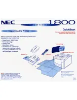
Electrodes location of the toner/drum unit

Fig. 3-2

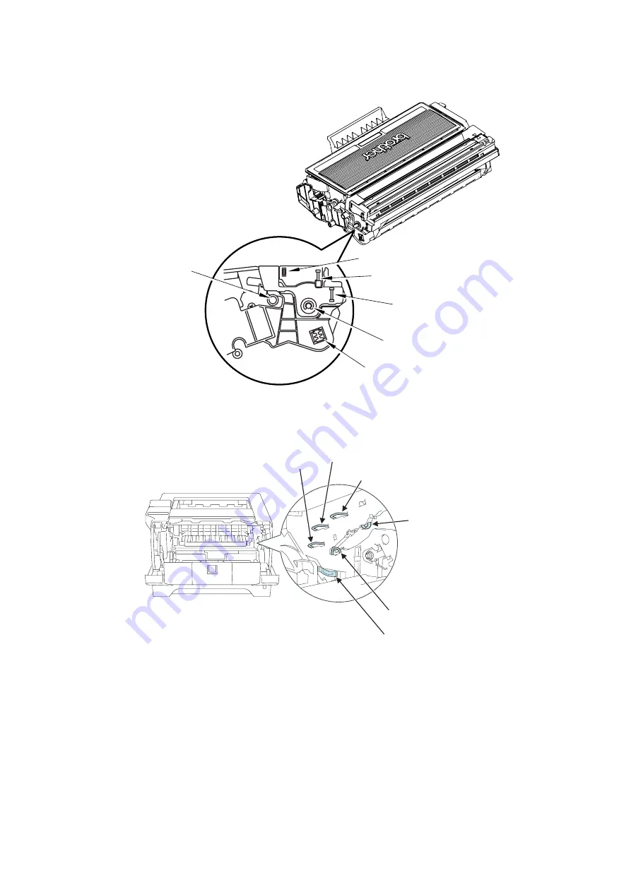
Electrodes location of the machine

Fig. 3-3

<How to clean the electrodes>

Turn off the power switch. Unplug the machine from the AC power outlet, and leave the machine 
for a few minutes.  Then, wipe the electrodes above carefully with a dry lint-free cloth.  Be 
careful not to change the shapes of the electrodes.

Toner/Drum Unit

(5) Grid

(7) Cleaner

(3) Charge

(4) Developer roller

(6) Transfer roller

(1) Exposure drum

Developer roller

Charge

Grid

Cleaner

Transfer roller

Exposure drum

Summary of Contents for HL 5370DW

Page 1: ... SERVICE MANUAL Read this manual thoroughly before maintenance work Keep this manual in a convenient place for quick and easy reference at all times December 2008 SM PRN072 MODEL HL 5340D 5350DN 5350DNLT HL 5370DW 5370DWT 5380DN ...

Page 2: ...ystems Inc in the United States Intel Intel Xeon and Pentium are trademarks or registered trademarks of Intel Corporation AMD AMD Athlon AMD Opteron and combinations thereof are trademarks of Advanced Micro Devices Inc PictBridge is a trademark Each company whose software title is mentioned in this manual has a Software License Agreement specific to its proprietary programs All other trademarks ar...

Page 3: ...oblems that could occur in the main sections of the machine and related troubleshooting procedures CHAPTER 4 PERIODIC MAINTENANCE Details of consumable parts and periodical maintenance parts This chapter also covers procedures for disassembling and assembling periodical maintenance parts CHAPTER 5 DISASSEMBLY REASSEMBLY Details of procedures for disassembling and assembling of the machine together...

Page 4: ...CES APPENDIX 6 GLOSSARY Information in this manual is subject to change due to improvement or redesign of the product All relevant information in such cases will be supplied in service information bulletins Technical Information A thorough understanding of this printer based on information in this service manual and service information bulletins is required for maintaining its print quality perfor...

Page 5: ...is needed This machine has a Class 3B laser diode which produces invisible laser radiation in the laser unit You should not open the laser unit under any circumstances Caution Use of controls or adjustments or performance of procedures other than those specified in this User s Guide may result in hazardous radiation exposure For Finland and Sweden LUOKAN 1 LASERLAITE KLASS 1 LASER APPARAT Varoitus...

Page 6: ...C and EN50419 European Union only This equipment is marked with the above recycling symbol It means that at the end of the life of the equipment you must dispose of it separately at an appropriate collection point and not place it in the normal domestic unsorted waste stream This will benefit the environment for all European Union only ...

Page 7: ...ful interference in a residential installation This equipment generates uses and can radiate radio frequency energy and if not installed and used in accordance with the instructions may cause harmful interference to radio communications However there is no guarantee that interference will not occur in a particular installation If this equipment does cause harmful interference to radio or televisio...

Page 8: ...al covers the laser beam cannot escape from the machine during any phase of user operation FDA Regulations 110 to 120 volt model only The U S Food and Drug Administration FDA has implemented regulations for laser products manufactured on and after August 2 1976 Compliance is mandatory for products marketed in the United States The following label on the back of the machine indicates compliance wit...

Page 9: ... Falle von Störungen der Lasereinheit muß diese ersetzt werden Das Gehäuse der Lasereinheit darf nicht geöffnet werden da sonst Laserstrahlen austreten können Location of the laser beam window ADDITIONAL INFORMATION Additional Information When servicing the optical system of the printer be careful not to place a screwdriver or other reflective object in the path of the laser beam Be sure to take o...

Page 10: ... help understand the machine WARNING Indicates warnings that must be observed to prevent possible personal injury CAUTION Indicates cautions that must be observed to service the printer properly or prevent damage to the printer Note Indicates notes and useful tips to remember when servicing the printer Listed below are the various kinds of WARNING messages included in this manual WARNING Always tu...

Page 11: ...ial caution should be exercised even if the power switch is OFF because it is a single pole switch WARNING DO NOT use flammable substances any type of spray or any organic solvent liquids contains alcohol or ammonia to clean the inside or outside of the machine Doing this may cause a fire or electrical shock ...

Page 12: ...CHAPTER 1 SPECIFICATIONS ...

Page 13: ...CONTENTS 1 COMPONENTS 1 1 2 SPECIFICATIONS LIST 1 2 2 1 Printing 1 2 2 2 Functions 1 3 2 3 Electronics and Mechanics 1 5 2 4 Network Connectivity 1 6 2 5 Service Information 1 8 2 6 Paper 1 9 2 6 1 Paper handling 1 9 2 6 2 Media specifications 1 10 2 6 3 Type and size of paper 1 10 2 7 Printable Area 1 12 2 8 Print Speeds with Various Settings 1 18 ...

Page 14: ...Top Cover Panel PCB Back Cover Outer Chute ASSY Rear Chute ASSY Fuser Unit Main PCB Access Cover Side Cover L Side Cover R Laser Unit Support Flap 1 Top Cover LCD LCD Panel PCB Support Flap 1 Toner LED PCB ASSY Paper Tray High voltage PS PCB PS PCB MP Tray Cover ASSY Process Cover ASSY Frame Unit ...

Page 15: ... A4 or Letter size paper from the standard paper tray Duplex A4 Up to 13 sides per minute 6 5 sheets per minute Letter Up to 14 sides per minute 7 sheets per minute Warm up time 2 From sleep mode less than 18 seconds From power off on less than 28 seconds First print time 2 Less than 8 5 seconds Consumables Toner cartridge Life expectancy Standard 3 000 pages cartridge High capacity 8 000 pages ca...

Page 16: ...BRAdmin Light Web BRAdmin Web Based Management BRAdmin Professional 3 Resident fonts PCL 66 scalable fonts 12 bitmap fonts 13 bar codes BR Script 3 66 scalable fonts Model HL 5340D HL 5350DN HL 5350DNLT HL 5370DW HL 5370DWT HL 5380DN Printer driver Windows PCL driver for Windows 2000 Professional XP Home Edition XP Professional Edition XP professional x64 Edition Server 2003 Server 2003 x64 Editio...

Page 17: ...ssional x64 Edition AMDOpteron AMDAthlon 64 Intel Xeon with Intel EM64T Intel Pentium 4 with Intel EM64T or equivalent 256MB 512MB 50MB Windows Server 2003 Intel Pentium III or equivalent 256MB 512MB 50MB Windows Server 2008 Intel Pentium 4 or equivalent 64 bit Intel 64 or AMD 64 supported CPU 512MB 2GB 50MB Windows XP Home Edition Intel Pentium or equivalent 128MB 256MB 50MB Windows XP Profession...

Page 18: ...Ad 4 6 Bell A Temperature Operating 10 to 32 5 C 50 to 90 5 F Non operating 0 to 40 C 38 to 104 F Storage 20 to 40 C 4 to 104 F Humidity Operating 20 to 80 non condensing Storage 10 to 85 non condensing Dimensions of the main body WxDxH 371x384x246mm 14 6x15 1x9 7in 371x384x 347mm 14 6x15 1x13 7in 371x384x 246mm 14 6x15 1x9 7in 371x384x 347mm 14 6x15 1x13 7in 393x384x 259mm 15 5x15 1x10 2in Weight...

Page 19: ...r HTTP HTTPS server TFTP client and server SMTP Client APOP POP before SMTP SMTP AUTH SNMPv1 v2c v3 ICMPv6 LLTD responder Web Services Print Network type 10 100 BASE TX Ethernet network Network printing Windows Vista Windows Server 2003 Windows XP and Windows 2000 TCP IP printing Mac OS X 10 3 9 or greater printing 1 If you want to use the IPv6 protocol visit http solutions brother com for more in...

Page 20: ...ommunication mode Infrastructure Ad hoc 802 11 b Data rate 802 11 b 11 5 5 2 1 Mbps 802 11 g 54 48 36 24 18 12 11 9 6 Mbps 1 A wireless network connection is supported only between the Brother printer and an access point for PC s running Windows Server 2003 x64 Edition and Windows XP Professional x64 Edition 2 If you want to use the IPv6 protocol visit http solutions brother com for more informati...

Page 21: ...000 hours MTTR Meantime to repair Average 0 5 hours Monthly volume 30 000 pages Periodical replacement parts As for periodical replacement parts refer to CHAPTER 4 in the Service Manual Parts Approximate Life pages Fuser unit 100 000 Laser unit 100 000 PF kit China MP 25 000 Tray 1 2 3 100 000 India MP 12 000 Tray 1 2 3 80 000 Others MP 50 000 Tray 1 2 3 100 000 ...

Page 22: ...HL 5370DW HL 5370DWT HL 5380DN Paper Input 1 Standard tray 250 sheets 500 sheets 250 sheets x 2 trays 250 sheets 500 sheets 250 sheets x 2 trays 250 sheets Multi purpose tray 50 sheets Option 250 sheets x 2 Max 500 sheets 250 sheets x 1 Max 250 sheets 250 sheets x 2 Max 500 sheets 250 sheets x 1 Max 250 sheets 250 sheets x 2 Max 500 sheets Paper Output 1 Face down 150 sheets Face up 1 sheet ...

Page 23: ...nd paper Recycled paper Envelope 4 Label Transparencies 3 Thin paper Optional tray Plain paper Bond paper Recycled paper Thin paper Media weight Paper tray Standard Option 60 to 105 g m2 16 to 28 lb Multi purpose tray 60 to 163 g m2 16 to 43 lb Duplex 60 to 105 g m2 16 to 28 lb Media size Paper tray Standard Option U S A A4 Letter B5 ISO A5 A5 Long Edge B6 ISO Legal 4 Folio A6 Exective Europe A4 L...

Page 24: ...75 g m2 16 to 20 lb Yes Yes Yes Thin paper Thick paper 105 to 163 g m2 28 to 43 lb N A Yes N A Thick Paper or Thicker Paper Labels N A Yes A4 or Letter N A Thicker Paper Envelopes N A Yes N A Envelopes Env Thin Env Thick Memo Use paper that is made for plain paper copying Use papers that is 75 to 90 g m2 20 to 24 lb Use neutral paper Do not use acidic or alkaline paper Use long grain paper This pr...

Page 25: ... printable area for a PCL driver Printable area shows mechanical printable area of the machine Therefore the machine can only print within the shaded area when you use a PCL driver Portrait A B C D E F G F G E G G Physical page Printable area Logical page B Physical page length D Maximum logical page length F Distance from edge of physical page to edge of logical page ...

Page 26: ... 0 16 50dots B 5 JIS 182 0mm 7 1 2 130dots 257 0mm 10 11 3 033dots 170 0mm 6 69 2 007dots 257 0mm 10 11 3 033dots 0mm 4 2mm 0 16 50dots B 5 ISO 176 0mm 6 93 2 078dots 250 0mm 9 84 2 952dots 164 0mm 6 46 1 936dots 250 0mm 9 84 2 952dots 0mm 4 2mm 0 16 50dots B 6 ISO 125 0mm 4 92 1 476dots 176 0mm 6 93 2 078dots 164 0mm 4 44 1 334dots 176 0mm 6 93 2 078dots 0mm 4 2mm 0 16 50dots Envelope Monarch 98 ...

Page 27: ...74dots 0mm 4 2mm 0 16 50dots 3X5 76 2mm 3 00 900dots 127 0mm 5 00 1 500dots 63 5mm 2 50 750dots 127 0mm 5 00 1 500dots 6 35mm 0 25 75dots 0mm 4 2mm 0 16 50dots Note The paper sizes indicated here should confirm to the nominal dimensions specified by JIS except B5 ISO B6 ISO The dot size is based on 300dpi resolution Size A B C D E F G ...

Page 28: ...al printable area of the machine Therefore the machine can only print within the shaded area when you use a PCL driver Landscape A B C D E F G F G E G G Physical page Printable area Logical page B Physical page length D Maximum logical page length F Distance from edge of physical page to edge of logical page ...

Page 29: ...ts 0mm 4 2mm 0 16 50dots B 5 JIS 257 0mm 10 11 3 033dots 182 0mm 7 1 2 130dots 247 0mm 9 72 2 916dots 182 0mm 7 1 2 130dots 0mm 4 2mm 0 16 50dots B 5 ISO 250 0mm 9 84 2 952dots 176 0mm 6 93 2 078dots 240 0mm 9 44 2 834dots 176 0mm 6 93 2 078dots 0mm 4 2mm 0 16 50dots B 6 ISO 176 0mm 6 93 2 078dots 125 0mm 4 92 1 476dots 166 4mm 6 55 1 960dots 125 0mm 4 92 1 476dots 0mm 4 2mm 0 16 50dots Envelope M...

Page 30: ...ots 0mm 4 2mm 0 16 50dots 3X5 127mm 5 00 1 500dots 76 2mm 3 00 900dots 116 8mm 4 60 1 380dots 76 2mm 3 00 900dots 5 0mm 0 20 60dots 0mm 4 2mm 0 16 50dots Note The paper sizes indicated here should confirm to the nominal dimensions specified by JIS except B5 ISO B6 ISO The dot size is based on 300 dpi resolution Size A B C D E F G ...

Page 31: ...all models Plain paper Recycled paper 0 to 90 second 32 ppm 90 second or later 15 ppm Plain paper thin 30 32 ppm Thick paper Envelopes Envelopes thick Label HAGAKI 0 to 9 second 16 ppm 9 second or later 15 ppm Thicker paper Bond paper Envelopes thick 3 ppm Note The print speed may vary according to conditions such as paper size and paper tray When a smaller size paper than A4 or Letter is printed ...

Page 32: ...Confidential CHAPTER 2 THEORY OF OPERATION ...

Page 33: ...ck Diagram 2 2 3 MECHANICS 2 3 3 1 Cross section Drawing 2 3 3 2 Cross section Drawing 2 4 3 2 1 Plate up Function of the Paper Tray 2 5 3 2 2 Paper supply 2 6 3 2 3 Paper registration 2 7 3 2 4 Paper eject 2 8 3 2 5 Duplex printing 2 9 3 2 6 Paper feeding from the MP tray 2 10 3 2 7 Paper feeding from the LT tray Tray 2 Tray 3 2 10 3 3 Toner Cartridge 2 11 3 3 1 Methods for Detecting and Counting...

Page 34: ...pply block Laser unit Drive block DC motor Drum unit Transfer block Exposure drum Charging block External device Paper tray Fuser unit Paper eject tray Paper feed system Image generation system Ethernet 10 100 Base TX Ethernet model Wireless LAN Extended RAM Paper dust cleaner block Toner cartridge Developing block Developer unit SODIMM 144pin RAM 16MB Netwark model 32MB No Netwark model Interface...

Page 35: ...B Light reception Main fan Toner LED PCB Light emission Power supply fan Interlock switch Cover sensor Wireless LAN Wireless LAN model MP sensor PCB Tray1 solenoid Regist solenoid Main motor Panel PCB DX solenoid DX unit sensor PCB MP solenoid LT solenoid Front relay PCB New toner sensor Rear relay PCB Paper eject sensor LT PCB LT1 LT Sensor PCB PE PEDGE LT solenoid LT PCB LT2 Polygon motor Laser ...

Page 36: ...r stack lever Paper tray Paper tray LT unit Paper feed roller MP Separation roller MP Paper feed roller Separation roller Regist actuator front Regist actuator rear PE actuator Feed roller TR Separation roller LT Feed roller LT Paper feed roller LT Edge actuator Plate Separation pad Separation pad MP MP tray Regist roller Develop roller Plate LT Separation pad LT PE actuator LT Edge actuator LT Ej...

Page 37: ...2 4 Confidential 3 2 Cross section Drawing The following figure shows the paper feeding paths Fig 2 4 LT path DX path MP path Paper tray path ...

Page 38: ...late ASSY so that it is pushed up Fig 2 5 When the feed roller is pushed up the hook is released by the lift arm and the rotation of the clutch gear is stopped Then the pressure plate is stopped to push up Fig 2 6 When the tray is pulled out from the printer the pressure plate is returned to the original position When the tray is put into the printer the above operation is performed from the start...

Page 39: ...are rotated Then the paper is gripped between the separation roller and separation pad and separated into individual sheets The paper drawn out of the paper tray pushes against the regist front actuator and the absence of paper is detected by the actuator movement The tail edge actuator detects the end of the paper fed Feed roller Separation roller Feed roller Pressure roller Edge actuator Plate P...

Page 40: ...regist solenoid is turned on the regist roller starts turning and the paper is fed to the transfer roller in the drum toner ASSY Fig 2 8 The regist actuator rear in the path from the regist roller to the transfer roller controls the first print position on the paper The printer starts transferring an image when a definite time passes after the paper is passed through the regist actuator rear Regis...

Page 41: ...r detects whether the paper is ejected correctly or not After the paper exits from the heat roller the paper is turned by the back cover and ejected face down into the top output tray through the eject roller 2 Fig 2 9 When a paper jam occurs the main motor rotates conversely to throw out the engagement of the gear Consequently the eject roller ASSY 2 is released so that the jammed recording paper...

Page 42: ...ller and the transfer roller to the transfer block in the drum unit again for process of printing on the back of sheet Fig 2 10 Note The duplex printing prints the 1st page after printing the 2nd page first For example when prints the four pages prints in order to 2nd page to 1st page to 4th page to 3rd page Regist roller Eject roller ASSY 2 Eject roller ASSY 1 Pressure roller Heat roller Exposure...

Page 43: ...r is separated into individual sheets by the separation roller MP Fig 2 11 3 2 7 Paper feeding from the LT tray Tray 2 Tray 3 The motor drive is transmitted to the some gears to rotate the feed roller then the recording paper is drawn out of the LT tray The drawn recording paper is separated into individual sheet by the separation roller and the separation pad and fed to the printer by the feed ro...

Page 44: ...ing two ways First such indication is displayed when detection is performed by the toner sensor second it is displayed at the time when a rotation rate of the develop roller reaches its upper limit 1 Detection by the toner sensor The low amount of toner remaining can be detected by checking the imperviousness to light of the toner in the cartridge by means of the transmissive photosensor 2 Detecti...

Page 45: ...f power switch ON and warming operation in company with opening or closing cover will also cause the deterioration of toner so the more frequency those operations be taken the less pages the toner cartridge can print Memo If reached the cartridge life end Replace Toner message appears even if the toner is contained Table The relationship between the average printing pages per job and the toner car...

Page 46: ... B on gear 4 When the toner actuator is pushed twice the two signals that are generated by the new toner sensor tell the machine that a standard toner cartridge has been installed 4 The high yield toner cartridge only has Rib A on gear 4 When the toner actuator is pushed once the signal that is generated by the new toner sensor tell the machine that a high yield toner cartridge has been installed ...

Page 47: ...cumulated number of prints with the toner cartridge The bias voltage is changed with the steps described below 1 When the new toner sensor detects that the toner cartridge is replaced with a new full one the developing bias is set to 400V initialized 2 After that the bias voltage is stepped down according to the number of prints Ultimately the bias voltage is 275V When a new toner cartridge is ins...

Page 48: ... a toner cartridge in use in which there is a little toner remained 2 The developing bias voltage is reset to the initial setting once when a toner cartridge in use is inserted Corresponding counter Setting value Operation Counter of toner cartridge changes No count up Page counter for each toner cartridge Continued Coverage for each toner cartridge Continued Developing bias voltage Reset Initial ...

Page 49: ...cally charged 2 Exposure A printed image is formed on the surface of the drum by applying laser beam 3 Development Toner is adhered to the surface of the drum 4 Transfer The toner on the surface of the exposure drum is transferred to paper 5 Fusing The transferred toner is fused into place on the paper After these processes the image is printed on the paper Fig 2 14 Charging Exposure Development T...

Page 50: ...e drum surface In order to coat toner on the exposure drum the drum needs to be evenly electrified Ions are produced by supplying high voltage power to the corona wire Fig 2 15 Memo The level of ozone expelled from the machine is less than 3 0 mg h therefore not harmful to the human body Applicable safety standards have been complied Corona wire Ion Grid Exposure drum ...

Page 51: ...nt width by a slit in the CO lens cell and then reflected by a polygon mirror rotating at high speed The evenly charged exposure drum is irradiated with reflected light and exposed Surface potential is lowered by such exposure and a printed image is formed Fig 2 16 CO lens Laser diode Laser unit Exposure drum Polygon mirror ...

Page 52: ...of toner taken to the drum is adjusted to keep printing density constant Fig Ref 2 17 Flow up of toner to the development process Toner adheres to the charged develop roller Such adhered toner is adjusted to an even thickness and is attracted to an exposed area on the exposure drum Fig 2 18 Charging 400 V to 275 V Changes depending on use condition Toner Develop roller Laser beam 150 V 850 V Blade...

Page 53: ...o the exposure drum is transferred to paper Fig 2 19 Memo Control of transfer bias The transfer bias applied in the transfer roller is adjusted according to types and sizes of paper so as to keep excellent image quality Exposure drum Transfer roller Toner Develop roller Supply roller Toner cartridge ...

Page 54: ...ressure The thermistor detects surface temperature of the heat roller and turns ON OFF the halogen heater lamp The temperature is kept constant Fig 2 20 Memo Control of fusing temperature The fuser unit adjusts such temperature according to types and sizes of paper so as to keep excellent image quality Fuser unit Heat roller Halogen heater Pressure roller ...

Page 55: ...type Toner LED PCB Light emission Photo sensor Frame R Detect whether the toner cartridge which contains enough toner Toner sensor PCB Light reception Photo sensor Frame L Front cover sensor Mechanical switch Frame L Detect the opening and closing of the front cover PE sensor Photo sensor PE EG sensor ASSY Detect the absence of the paper in the paper tray Edge sensor Photo sensor PE EG sensor ASSY...

Page 56: ... sensor PCB Light reception Regist frame Paper feed frame MP PE sensor PE EG sensor PE sensor Edge sensor Regist front sensor High voltage PS PCB Regist rear sensor New toner sensor PCB Relay front PCB DX tray sensor Paper eject sensor Relay rear PCB Frame L Front cover sensor ...

Page 57: ...Confidential CHAPTER 3 ERROR INDICATION AND TROUBLESHOOTING ...

Page 58: ...nitial Check 3 3 2 DISTINGUISH ERROR CAUSE 3 5 2 1 LED indication LED model 3 5 2 1 1 LED indication at Operator Calls 3 5 2 1 2 LED indication at Service Calls 3 9 2 2 Error Message LCD model 3 14 2 2 1 Operator calls 3 14 2 2 2 Error indication at Service Calls 3 15 2 3 Error Cause and Remedy 3 16 3 PAPER FEEDING PROBLEMS 3 29 3 1 No Feeding 3 29 3 2 Double Feeding 3 29 3 3 Paper Jam 3 30 3 4 Di...

Page 59: ...the power cable before removing any covers or PCBs adjusting the machine and so on If you need to take voltage measurements with the power switched on take the greatest of care not to receive an electric shock 2 When connecting or disconnecting cable connectors make sure that you hold the connector body and not the cables 3 Electronic devices are sensitive to static build up make sure that you tou...

Page 60: ...er Outer Chute ASSY Rear Chute ASSY Fuser Unit Main PCB Access Cover Side Cover L Side Cover R Laser Unit Support Flap 1 Top Cover LCD LCD Panel PCB Support Flap 1 Toner LED PCB ASSY Paper Tray High voltage PS PCB PS PCB MP Tray Cover ASSY Process Cover ASSY Frame Unit ...

Page 61: ...t short grained paper or acid paper Consumable Parts 1 The drum unit including the toner cartridge is installed correctly Others 1 Condensation When the machine is moved from a cold place into a warm room condensation may occur inside the machine causing various problems as listed below Condensation on the optical surfaces such as the scanner window lenses the reflection mirror and the protection ...

Page 62: ...2 Cleaning Use a soft dry cloth warning DO NOT use flammable substances such as alcohol benzine thinner or any type of spray to clean the inside or outside of the machine Doing this may cause a fire or electrical shock ...

Page 63: ...ut some of errors are necessary to reset the machine by holding down the Go button LED indication of the following table is that LED is OFF LED is ON and LED is blinking LED Type of error Error clearance by pressing the Go button Refer to Front cover is opened No 3 19 Memory full Yes 3 22 Option tray is installed too much No 3 24 Print overrun Yes 3 23 Fuser cover is opened No 3 20 DX unit is not ...

Page 64: ... jammed in backside machine No 3 20 Paper is jammed in DX unit No LED Type of error Error clearance by pressing the Go button Refer to Back Cover Toner Drum Paper Status Status Red light ON Back Cover Toner Drum Paper Status Status Red light ON The Paper LED will turn on for 0 5 seconds and off for 0 5 seconds Back Cover Toner Drum Paper Status Status Red light ON The Back Cover and Paper LED will...

Page 65: ... the Go button Refer to Back Cover Toner Drum Paper Status Status Red light ON Back Cover Toner Drum Paper Status Status Green light ON The Toner LED will turn on for 2 seconds and off for 3 seconds Back Cover Toner Drum Paper Status Status Green light ON The Drum LED will turn on for 2 seconds and off for 3 seconds ...

Page 66: ...e end 3 23 No paper in specified tray No 3 22 LED Type of error Error clearance by pressing the Go button Refer to Back Cover Toner Drum Paper Status Status Green light ON Back Cover Toner Drum Paper Status Status Red light ON ...

Page 67: ... button once at the same time Press the Job Cancel button twice while pressing the Go button Type of error Refer to Fuser NVRAM error 3 26 Fuser low temperature error 60 C 3 26 Fuser abrupt Lower of temperature 3 26 Passed for 9 seconds till became 100 C from 60 C 3 26 All LEDs will turn on for 0 5 seconds and off for 0 5 seconds Back Cover Toner Drum Paper Status Back Cover Toner Drum Paper Statu...

Page 68: ...of error Refer to All LEDs will turn on for 0 5 seconds and off for 0 5 seconds Back Cover Toner Drum Paper Status Back Cover Toner Drum Paper Status Status Red light ON Fuser unit error Back Cover Toner Drum Paper Status Status Green light ON Back Cover Toner Drum Paper Status Status Green light ON Back Cover Toner Drum Paper Status Status Green light ON Back Cover Toner Drum Paper Status Status ...

Page 69: ...Press the Job Cancel button twice while pressing the Go button Type of error Refer to All LEDs will turn on for 0 5 seconds and off for 0 5 seconds Back Cover Toner Drum Paper Status Back Cover Toner Drum Paper Status Status Red light ON Main PCB error Back Cover Toner Drum Paper Status Status Green light ON Back Cover Toner Drum Paper Status Status Green light ON Back Cover Toner Drum Paper Statu...

Page 70: ...ton Type of error Refer to All LEDs will turn on for 0 5 seconds and off for 0 5 seconds Back Cover Toner Drum Paper Status Back Cover Toner Drum Paper Status Status Red light ON Laser unit error Back Cover Toner Drum Paper Status Status Green light ON Back Cover Toner Drum Paper Status Status Green light ON Back Cover Toner Drum Paper Status Status Red light ON Back Cover Toner Drum Paper Status ...

Page 71: ...Cancel button once at the same time Press the Job Cancel button twice while pressing the Go button Type of error Refer to All LEDs will turn on for 0 5 seconds and off for 0 5 seconds Back Cover Toner Drum Paper Status Back Cover Toner Drum Paper Status Status Red light ON ...

Page 72: ... reached 90 of the time for replacement 3 17 DRUM ERROR Dirt on drum unit Dirt on the corona wire 3 17 DUPLEX DISABLED The back cover is open or the DX unit is not set 3 19 FONT FULL The number of the registration of the font is overflowed 3 19 FRONT COVER OPEN Front cover is opened 3 19 FUSER COVER OPEN Fuser cover is opened 3 20 JAM XXX No paper in Tray 1 T1 2 T2 3 T3 3 20 MANUAL FEED No paper i...

Page 73: ...R S01 ERROR S01 MAIN PCB FAILURE 3 25 ERROR S02 ERROR S02 ERROR S03 ERROR S03 ERROR S04 ERROR S04 ERROR S05 ERROR S05 ERROR S06 ERROR S06 ERROR S07 ERROR S07 ERROR S08 ERROR S08 ERROR S09 ERROR S09 ERROR S10 ERROR S10 ERROR S11 ERROR S11 ERROR S12 ERROR S12 ERROR S13 ERROR S13 ERROR E49 FUSER MALF 2 FUSER UNITFAILURE 3 26 ERROR E50 FUSER MALF ERROR FUSER ERROR FUSER ERROR E51 LASER BD MALF LASER U...

Page 74: ...place the main PCB ASSY User Check Install the toner cartridges into the machine properly Step Cause Remedy 1 Power off or front cover opened while detecting a new toner cartridge Reset the developing bias voltage and develop roller counter Refer to Developer Roller Counter Reset in 1 3 Service Mode in Chapter 7 2 New toner actuator catching on some position Re assemble the new toner actuator 3 Ne...

Page 75: ...Menu in Chapter 7 User Check Clean the corona wire in the drum unit Replace the drum unit with a new one and reset the drum counter Step Cause Remedy 1 Dirt or dust on drum unit electrodes Clean the electrodes on the drum unit and the machine body Refer to Fig 3 2 Fig 3 3 2 High voltage power supply PCB failure Replace the high voltage power supply PCB 3 Main PCB ASSY failure Replace the main PCB ...

Page 76: ...Unplug the machine from the AC power outlet and leave the machine for a few minutes Then wipe the electrodes above carefully with a dry lint free cloth Be careful not to change the shapes of the electrodes Toner Drum Unit 5 Grid 7 Cleaner 3 Charge 4 Developer roller 6 Transfer roller 1 Exposure drum Developer roller Charge Grid Cleaner Transfer roller Exposure drum ...

Page 77: ...ilure Replace the main PCB ASSY User Check Cut down the registration of the font Add on the DIMM Step Cause Remedy 1 Main PCB ASSY failure Replace the main PCB ASSY User Check Check if the front cover is closed certainly Step Cause Remedy 1 Harness connection failure of interlock SW ASSY Check the harness connection of the interlock SW ASSY and reconnect it 2 Interlock SW ASSY failure Check the se...

Page 78: ...priate tray If jammed remove it Adjust the paper guide corresponding to the paper size Check if too much paper is loaded in the tray Step Cause Remedy 1 Edge actuator or registration front actuator catching on some position Correct catching of the edge actuator or registration front actuator 2 Paper feeding kit worn out Replace the paper feeding kit 3 Harness connection failure of High Voltage PS ...

Page 79: ...owing the procedure in Factory Inspection Mode in 1 3 Service Mode in Chapter 7 If any problem occurs replace the relay rear PCB ASSY 4b High Voltage PS PCB ASSY failure Check the sensor performance following the procedure in Factory Inspection Mode in 1 3 Service Mode in Chapter 7 If any problem occurs replace the High Voltage PS PCB ASSY 5 Main PCB ASSY failure Replace the main PCB ASSY 6 Regist...

Page 80: ...tion failure of high voltage PS PCB ASSY Check the harness connection of the high voltage PS PCB ASSY and reconnect it 4 PE EG sensor ASSY failure Replace the PE PG sensor ASSY 5 High voltage PS PCB ASSY failure Replace the high voltage PS PCB ASSY 6 Main PCB ASSY failure Replace the main PCB ASSY User Check Install the toner cartridge Step Cause Remedy 1 Harness connection failure of toner sensor...

Page 81: ...ode in 1 3 Service Mode in Chapter 7 If any problem occurs check the harness connection of the PE EG sensor ASSY 2 LT PCB ASSY failure Replace the LT PCB ASSY 3 Connector 55533 1219 Replace the connector 55533 1219 4 PE EG sensor ASSY of T1 or T2 failure Replace the PE EG sensor ASSY of the T1 or T2 5 Main PCB ASSY failure Replace the main PCB ASSY User Check Reduce the complexity of data or reduc...

Page 82: ... 2 3 MP is the time for replacement Replace the PF kit 1 2 3 MP and reset the counter Refer to 2 2 Reset Parts Life Menu in Chapter 7 User Check Specify the paper size to A4 LETTER FOLIO User Check Match specified paper size from the driver with setting paper in the tray User Check Install additional DIMM memory Step Cause Remedy 1 Main PCB ASSY failure Replace the main PCB ASSY User Check Install...

Page 83: ...failure Replace the panel PCB ASSY 4 Main PCB ASSY failure Replace the main PCB ASSY User Check Replace the toner cartridge Step Cause Remedy 1 Harness connection failure of toner sensor PCB ASSY Check the sensor performance following the procedure in Factory Inspection Mode in 1 3 Service Mode in Chapter 7 If any problem occurs check the harness connection of the toner sensor PCB ASSY then reconn...

Page 84: ...rn the power on while pressing the Go button when the front cover is open And check that USERS MODE is displayed on the LCD and then release the Go button Check that Data LED go off and press the Go button twice and then this problem may be cleared by that press the Go button once again after USERS MODE is displayed on the LCD in the state that the backlight lights up This operation will melt the ...

Page 85: ...ess connection of the fan motor 60 unit and reconnect it 2 Fan failure Replace the fan motor 60 unit 3 Toner LED PCB failure Replace the toner LED PCB ASSY 4 Main PCB failure Replace the main PCB ASSY Step Cause Remedy 1 Harness connection failure of panel PCB Reconnect the panel PCB ASSY harness 2 AC cord failure Replace the AC cord 3 Panel PCB failure Replace the panel PCB ASSY 4 LVPS PCB failur...

Page 86: ... 4 New toner actuator failure Replace the new toner actuator 5 New toner sensor PCB ASSY failure Replace the new toner sensor PCB ASSY 6 Main PCB ASSY failure Replace the main PCB ASSY Step Cause Remedy 1 Panel PCB harness connection failure Check the harness connection of the panel PCB then reconnect it 2 Panel PCB failure Replace the panel PCB 3 Main PCB ASSY failure Replace the main PCB ASSY St...

Page 87: ... pad or roller holder ASSY failure Is the surface of the separation pad or the pickup roller dirty or worn out Yes 1 Clean the surface of the separation pad or pickup roller 2 Replace the separation pad or pickup roller 5 Pressure plate gear damage Is the pressure plate gear damaged Yes Replace the paper tray 6 T1 solenoid failure Does the T1 solenoid work correctly No Replace the T1 solenoid 7 T1...

Page 88: ...er LED PCB ASSY 5 High voltage power supply PCB failure Is the problem solved after replacing the High voltage power supply PCB ASSY Yes Replace the High voltage power supply PCB ASSY 6 Main PCB failure Is the problem solved after replacing the Main PCB ASSY Yes Replace the Main PCB ASSY Step Cause Check Result Remedy 1 Foreign object around fuser unit Is there a foreign object around the fuser un...

Page 89: ...othly No Re assemble the LT edge actuator 2 LT sensor PCB ASSY failure Is the problem solved after replacing the LT sensor PCB ASSY Yes Replace the LT sensor PCB ASSY 3 LT solenoid failure Is the problem solved after replacing the LT solenoid Yes Replace the LT solenoid Step Cause Check Result Remedy 1 DX unit failure Is the problem solved after replacing the DX unit Yes Replace the DX unit ...

Page 90: ... the paper is loaded into the paper tray correctly Turn over the stack of paper in the paper tray or try rotating the paper 180 in the paper tray Step Cause Check Result Remedy 1 Fuser unit dirty Is there dirt around the entrance of the fuser unit Yes Clean the entrance of the fuser unit 2 Fuser unit failure Is the problem solved if new fuser unit is replaced Yes Replace the fuser unit User Check ...

Page 91: ...duplex printing The curl in the left figure User Check Change the paper Step Cause Check Result Remedy 1 Mismatch the setting the paper and the eject roller 1 Is the problem solved by changing the position of the anti curl lever Yes Change the position of the anti curl lever Step Cause Check Result Remedy 1 Used small paper Is the A4 LETTER used No Use the paper of the A4 LETTER 2 1 ...

Page 92: ... 2 Exposure drum Ø30 0 mm 94 2 mm 3 Heat roller in the fuser unit Ø25 0 mm 78 5 mm 4 Pressure roller ASSY in the fuser unit Ø25 0 mm 78 5 mm 5 Registration roller Ø14 0 mm 44 0 mm 6 Transfer roller Ø15 2 mm 48 2 mm Light Poor fixing Dirt on the back of paper White vertical streaks Faint print Black spots Downward fogging of solid color Horizontal lines Ghost Fogging Hollow print by condensation Bl...

Page 93: ...ean lint free cloth Refer to Fig 3 6 3 Toner sensor failure After replacing the toner cartridge with a new one does the same problem occur even after printing several pages No Replace the toner cartridge 4 Does the machine start printing even after removing the toner cartridge from the drum unit Yes Clean the toner sensor receiving light side emitting light side Check the harness connection of the...

Page 94: ...re and high humidity conditions can cause this problem Replace the drum unit with a new one Replace the toner cartridge with a new one Step Cause Check Result Remedy 1 Drum unit electrode dirty Is the electrode of the drum unit dirty Yes Clean the electrode 2 Drum unit failure Is the problem solved after replacing the drum unit Yes Replace the drum unit 3 Developing bias malfunciton Is the problem...

Page 95: ...m solved after replacing the fuser unit Yes Replace the fuser unit 3 Toner sensor failure Is the Toner life End message indicated on the LCD after replacing the current toner cartridge with a new one No Replace the toner sensor 4 HVPS PCB failure Is the problem solved after replacing the HVPS PCB ASSY Yes Replace the HVPS PCB ASSY 5 Main PCB failure Is the problem solved after replacing the main P...

Page 96: ...r replacing the laser unit Yes Replace the laser unit 4 HVPS PCB failure Is the problem solved after replacing the HVPS PCB ASSY Yes Replace the HVPS PCB ASSY 5 Main PCB failure Is the problem solved after replacing the main PCB ASSY Yes Replace the main PCB ASSY Step Cause Check Result Remedy 1 Laser unit not assembled correctly Is the laser unit assembled into the machine securely Check if there...

Page 97: ...No Reconnect the scanner harness of the laser unit 4 FG harness ASSYconnection failure Is the FG harness ASSY between the laser unit and main PCB ASSY connected securely No Reconnect the FG harness ASSY between the laser unit and main PCB ASSY securely 5 HVPS PCB failure Is the problem solved after replacing the HVPS PCB ASSY Yes Replace the HVPS PCB ASSY 6 Main PCB failure Is the problem solved a...

Page 98: ... Replace the toner cartridge with a new one Step Cause Check Result Remedy 1 Scratch and Dirt in the paper feed system Is the paper feed system dirty Yes Wipe dirt off 2 Scratch and Dirt on the exposure drum Are there scratch and dirt on the surface of the exposure drum Yes Replace the drum unit 3 Scratch and Dirt on the heat roller Are there scratch and dirt on the surface of the heat roller Yes ...

Page 99: ...on the develop roller Are the horizontal stripes at 42 5 mm develop roller circumference intervals Yes This problem will disappear by printing approximate 10 pages If the same problem occurs replace the toner cartridge 4 Scratch and Dirt on the exposure drum Are the horizontal stripes at 94 2 mm exposure drum circumference intervals Yes Replace the drum unit 5 Scratch and Dirt on the heat roller A...

Page 100: ...perature 2 Transfer failure Is the transfer roller scratched Yes Replace the drum unit 3 Scanner windows of laser unit failure Is the problem solved after replacing the laser unit Yes Replace the laser unit User Check Check that the appropriate media type is selected in the printer driver The problem may disappear by itself Try printing multiple pages to clear this problem especially if the machin...

Page 101: ...not solved after printing a few pages the drum unit may have glue from label stock on the exposure drum surface Refer to the next page and wipe it off gently with a cotton swab The drum unit may be damaged Replace the drum unit with a new one Step Cause Check Result Remedy 1 Toner attached on the develop roller Are the horizontal stripes at 42 5 mm develop roller circumference intervals Yes This p...

Page 102: ...ig 3 8 2 Turn the drum unit gear to the direction of the arrow of the figure by hand while looking at the surface of the exposure drum Fig 3 9 3 When you have found the mark on the drum that matches the print sample wipe the surface of the exposure drum with a dry cotton swab until the dust or glue on the surface comes off Fig 3 10 CAUTION DO NOT clean the surface of the photosensitive drum with a...

Page 103: ...artridge 2 Scratch and Dirt on the exposure drum Are the horizontal stripes at 94 2 mm exposure drum circumference intervals Yes Replace the drum unit 3 Drum unit connection failure Are the electrodes on the drum unit and machine body dirty Yes Clean both electrodes Refer to Fig 3 2 Fig 3 3 4 Scratch and Dirt on the heat roller Are the horizontal stripes at 78 5 mm heat roller circumference interv...

Page 104: ... PCB ASSY 3 Main PCB failure Is the problem solved after replacing the main PCB ASSY Yes Replace the main PCB ASSY User Check The paper tray ground terminal provided in the machine body may be dirty Clean the contact with a dry cloth Step Cause Check Result Remedy 1 Dirt on charged electrode Are the electrodes on the drum unit and machine body dirty Yes Clean both electrodes Refer to Fig 3 2 Fig 3...

Page 105: ...ace the toner cartridge with a new one Replace the drum unit with a new one Do not use acid paper Check if there is dust or paper powder in the machine Step Cause Check Result Remedy 1 Toner sensor failure Machine body Is the toner sensor performed normally by following the procedure in Factory Inspection Mode in 1 3 Service Mode in Chapter 7 No Replace the toner sensor PCB unit ASSY and the toner...

Page 106: ...a few minutes Step Cause Check Result Remedy 1 Condensation of drum unit by high humidity environment Is the problem solved after setting the drum condensation countermeasure mode to ON Yes Drum condensation countermeasure mode is set to ON Refer to 3 2 Drum condensation countermeasure mode in Chapter 7 ...

Page 107: ... settings Refer to Users guide Step Cause Check Result Remedy 1 Failure inside the machine Does the machine print Printer Settings Refer to Printing for Maintenance in 1 3 Service Mode in Chapter 7 No Identify the error type and then refer to the specified section of this chapter 2 Machine connection For Macintosh has the product ID been verified No Verify the product ID Product ID HL 5340D 0039 H...

Page 108: ...tting the factory settings Step Cause Check Result Remedy 1 Wireless LAN PCB failure HL 5370DW 5370DWT Is the problem solved after replacing the wireless LAN PCB ASSY Yes Replace the wireless LAN PCB ASSY 2 Main PCB failure Is the problem solved after replacing the main PCB ASSY Yes Replace the main PCB ASSY ...

Page 109: ...Confidential CHAPTER 4 PERIODIC MAINTENANCE ...

Page 110: ...TS 1 PERIODIC MAINTENANCE PARTS 4 1 1 1 Periodical Replacement Parts 4 2 1 2 Procedures to Replace Periodical Replacement Parts 4 3 1 2 1 Fuser unit and laser unit 4 3 1 2 2 Paper feeding kit for tray 1 2 3 4 24 1 2 3 Paper feeding kit for MP tray 4 30 ...

Page 111: ...he power cord from the power outlet before accessing any parts inside the machine When opening the front cover or back cover to access any parts inside the machine never touch the shaded parts shown in the following figures DO NOT use flammable substances such as alcohol benzine thinner or any type of spray to clean the inside or outside of the machine Doing this may cause a fire or electrical sho...

Page 112: ...of prints Replacement Procedure Fuser Unit REPLACE FUSER 1 100 000 pages See subscription 1 2 1 Chapter 4 Laser Unit REPLACE LASER 1 100 000 pages PF kit for Tray 1 3 REPLACE PF KIT1 1 Except for India 100 000 pages See subscription 1 2 2 Chapter 4 India 80 000 pages PF kit for Tray 2 3 REPLACE PF KIT2 1 Except for India 100 000 pages India 80 000 pages PF kit for Tray 3 3 REPLACE PF KIT3 1 Except...

Page 113: ...g the procedures Make sure that the AC cord is disconnected from the printer Make sure that the Drum toner ASSY is removed Make sure that the DX feed ASSY or DX blank cover is removed Make sure that the Paper is removed from the Paper tray 1 Open the Back cover 2 Remove the Pins of the Outer chute from the Back cover Fig 4 1 Pin Pin Back cover Back cover Outer chute ...

Page 114: ... 4 Remove the Back cover Fig 4 2 5 Hold the Knobs on the Rear chute ASSY and pull down this to your side 6 Remove the Arms of the Rear chute ASSY from the Pins 7 Remove the Rear chute ASSY Fig 4 3 Pin Arm Arm Pin Back cover Pin Pin Knob Knob Rear chute ASSY 5 5 5 6 7 ...

Page 115: ...in the order of 8a 8b and 8c Remove the FU harness cover 1 Fig 4 4 9 Disconnect the connector of the Heater terminal while pressing the Hook of the connector of the Fuser unit Fig 4 5 Hook FU harness cover 1 Taptite pan B M4x20 8a 8b 8c Hook Flame R Fuser unit Heater terminal ...

Page 116: ...r 2 from the back of the printer Fig 4 6 11 Disconnect the connectors of the Thermistor ASSY M and Thermistor ASSY S from the Relay rear PCB ASSY and remove the harnesses of these thermistors Fig 4 7 FU harness cover 2 3a 3b 10a Hook Thermistor ASSY S Thermistor ASSY M Fuser unit Hook Hook Relay rear PCB ASSY Relay rear PCB ASSY ...

Page 117: ... 13 Open the Front cover remove the two bind B M4x12 Taptite screws and then remove the Side cover L by releasing the Hooks in the order of 13a to 13d Fig 4 9 Taptite pan B M4x20 Fuser unit Taptite bind B M4x12 Hooks Hooks Hooks 13b 13a 13c 13d Side cover L Front cover Taptite bind B M4x12 ...

Page 118: ...s Fig 4 10 15 Remove the two bind B M4x12 Taptite screws and then remove the Side cover R by following the direction from 15a to 15d Fig 4 11 Taptite cup S M3x6 SR Taptite cup S M3x6 SR FG harness Shield cover Taptite bind B M4x12 Taptite bind B M4x12 Hook Hook Hooks Hooks Hooks Shield cover R 15d 15c 15a 15b ...

Page 119: ...rews from Top cover printed ASSY 18 Release all Hooks of the Top cover printed ASSY and lift up the front side of the Top cover printed ASSY 19 Remove the Top cover printed ASSY Fig 4 13 Top cover printed ASSY Connector Main PCB Panel PCB Hook Top cover printed ASSY Taptite bind B M4x12 Hook Hooks Hook Hook 19 18 ...

Page 120: ... 20b while pressing the Hook to the direction of 20a and remove the Sub duct from the Air duct Fig 4 14 22 Remove the Filter from the Air duct Fig 4 15 Note The filter is dirt Be careful when disassembling or assembling it 21a 21b 21c 20 Hook Air duct Wireless PCB harness Hook Sub duct Back side Air duct Filter ...

Page 121: ...4 11 Confidential 23 Remove the Pin of the Air duct from the frame Slide the Air duct to the direction of 22b and remove the Air duct Fig 4 16 Pin Hook Pin Hook Hook Laser unit Air duct 22b 22a ...

Page 122: ...ck that each cable is not damaged at its end or short circuited Note Be careful not to lose the Protective film attached on the flat cable Do not touch the Laser scanner window directly Taptite cup S M3x6 Polygon motor connector Flat cable LD harness connector Flat cable Wireless PCB harness core Protective film Laser unit Taptite cup S M3x6 Core LD harness connector Flat cable Protective film Mai...

Page 123: ...ter 5 4 Connect the two Flat cables to the Main PCB Fig 4 18 Note When connecting flat cable s do not insert them at an angle After insertion check that the cables are not at an angle Taptite cup S M3x6 Polygon motor connector Flat cable LD harness connector Flat cable Wireless PCB harness core Protective film Laser unit Taptite cup S M3x6 Core LD harness connector Flat cable Protective film Main ...

Page 124: ...4 14 Confidential 5 Install the Air duct into the Laser unit Fig 4 19 6 Install the Filter into the Air duct Fig 4 20 Laser unit Air duct Air duct Filter ...

Page 125: ...e harness of the wireless PCB ASSY Fig 4 21 9 Secure the Top cover printed ASSY with the two bind B M4x12 Taptite screws Fig 4 22 8 Hook Air duct Wireless PCB harness Sub duct Back side 7a 7b Hook Top cover printed ASSY Taptite bind B M4x12 Hook Hooks Hook Hooks Hook 9a 9b ...

Page 126: ...anel PCB Fig 4 23 11 Catch the all Hooks and secure the Side cover R with the two bind B M4x12 Taptite screws Fig 4 24 Top cover printed ASSY Connector Main PCB Panel PCB Taptite bind B M4x12 Taptite bind B M4x12 Hook Hook Hooks Hooks Hooks Side cover R ...

Page 127: ...p S M3x6 SR Taptite screws Fig 4 25 13 Catch the all Hooks and secure the Side cover L with the two bind B M4x12 Taptite screws Fig 4 26 Taptite cup S M3x6 SR Taptite cup S M3x6 SR FG harness Shield cover Taptite bind B M4x12 Hooks Hooks Hooks Side cover L Taptite bind B M4x12 ...

Page 128: ...mation of the pressure roller the fuser unit spare part is shipped with its pressure roller at low nip pressure Before installing the fuser unit turn back the levers to the normal position by following instructions below 1 Put the fuser unit on a flat horizontal surface Pull up each of the black tab a on the right side and left side 2 Make sure that the black lever b is in the position in the illu...

Page 129: ...4 19 Confidential 14 Secure the Fuser unit with the pan B M4x20 Taptite screw Fig 4 27 Taptite pan B M4x20 Fuser unit ...

Page 130: ...hermistor ASSY M and Thermistor ASSY S onto the Relay rear PCB ASSY Fig 4 28 16 Install the FU harness cover 2 Fig 4 29 Thermistor ASSY S Thermistor ASSY M Fuser unit Hook Hook Relay rear PCB ASSY Relay rear PCB ASSY Hook FU harness cover 2 3a 3b 16b 16a ...

Page 131: ... 30 18 Secure the FU harness cover 1 with the pan B M4x20 Taptite screw Fig 4 31 Note Do not sandwich the harness of the heater terminal by the FU harness cover 1 Hook Flame R Fuser unit Heater terminal Hooks FU harness cover 1 Taptite pan B M4x20 18b 18a ...

Page 132: ... ASSY onto the Pin of the machine body and install the Rear chute ASSY Fig 4 32 20 Catch the Arm of the Back cover onto the Pin of the machine body and install the Back cover Fig 4 33 Pin Rear chute ASSY 19c 19b 19a Pin Pin Arm arm Pin Back cover 20a 20b ...

Page 133: ...wing parts after assembling Set the DX feed ASSY or DX blank cover Install the Drum toner ASSY into the Printer Put the Paper into the Paper tray Reset the count of the Fuser unit and Laser unit after part replacement Refer to 2 2 Reset Parts Life Menu in Chapter 7 Pin Pin Back cover Back cover Outer chute 21a 21a 21b 21b ...

Page 134: ...r ASSY is removed Make sure that the DX feed ASSY or DX blank cover is removed Make sure that the Paper is removed from the Paper tray 1 Pull up the back side of the Separation pad ASSY 2 Push the Hooks provided on both sides of the Separation pad ASSY inwards 3 Pull up the Separation pad ASSY 4 Remove the Separation pad spring Fig 4 35 Separation pad ASSY Hooks Hook Separation pad spring Hook Pap...

Page 135: ...t the pin of the Roller holder ASSY Then turn the Roller holder ASSY to the direction of the arrow 6b Fig 4 36 Note Pull out and put into the paper tray so that the Roller holder ASSY is lowered If the Roller holder ASSY is remained up it cannot be removed Lift arm Pin Roller holder ASSY 6a 6b Paper feed frame 6a ...

Page 136: ...lder ASSY to the direction of the arrow 7a Then lift up the gear side of the Roller holder ASSY to the direction of the arrow 7b and pull it out to the direction of the arrow 7c to remove Fig 4 37 7c 7b 7a Roller holder ASSY Paper feed frame ...

Page 137: ...edure 1 Install the Roller holder ASSY Fig 4 38 Note When assembling the roller holder ASSY align the section A on the shaft of the roller holder ASSY with the hole on the paper feed frame 1c 1b 1a Roller holder ASSY A Paper feed frame ...

Page 138: ...e the Lift arm onto the Pin of the Roller holder ASSY 3 Place the Printer on its base Fig 4 39 4 Install the DX feed ASSY or DX blank cover and install the Drum toner ASSY 2a 2b Lift arm Pin Roller holder ASSY Paper feed frame 2b ...

Page 139: ...ation pad ASSY to the direction of the arrow 6c to catch the Hooks into the Paper tray Fig 4 40 7 Put the Paper tray into the Printer Reset the count of the PF Kit after part replacement Note Check that the Separation pad spring is assembled correctly 6b 6a 6c 6b Separation pad ASSY Hooks Hook Separation pad spring Hook Paper tray ...

Page 140: ...lling Procedure Check that the following before entering the procedures Make sure that the AC cord is disconnected from the printer Make sure that the Drum toner ASSY is removed 1 Open the MP feed frame cover Fig 4 41 MP feed frame MP feed frame cover Front cover ...

Page 141: ...Lift arm MP to release it from the Pin of the MP roller holder ASSY 4 Slide the MP roller holder ASSY to the direction of the arrow 4a and put it up to remove Fig 4 43 2a 2b 2c MP feed frame Hook Holder bearing MP 4a 3 4b Pin Lift arm MP MP feed frame MP roller holder ASSY ...

Page 142: ...4 32 Confidential 5 Turn the back side of the Separation pad ASSY MP to the direction of the arrow 5a and put it up to remove Fig 4 44 5b Separation pad ASSY MP MP feed frame MP frame 5a 5a ...

Page 143: ...ASSY MP to the direction of the arrow 1b until it is locked Fig 4 45 2 Lift up the Lift arm MP and put the MP roller holder ASSY into the MP feed frame Put the Pin of the MP roller holder ASSY into the hole of the Lift arm MP Fig 4 46 1a MP feed frame MP frame Separation pad ASSY MP 1b 1b MP feed frame Lift arm MP MP roller holder ASSY Pin ...

Page 144: ...he direction of the arrow 3c to lock Fig 4 47 4 Close the MP feed frame cover Fig 4 48 5 Install the Drum toner ASSY into the Printer 6 Close the Front cover Reset the count of the PF Kit MP after part replacement 3a 3b 3c MP feed frame Holder bearing MP Hook MP feed frame MP feed frame cover Front cover ...

Page 145: ...CHAPTER 5 DISASSEMBLY REASSEMBLY ...

Page 146: ...HARNESS ROUTING 5 8 7 DISASSEMBLY FLOW CHART 5 18 8 DISASSEMBLY PROCEDURE 5 19 8 1 Paper Tray 5 20 8 2 Back Cover 5 23 8 3 Rear Chute ASSY 5 25 8 4 Fuser Unit 5 27 8 5 Tray MP ASSY 5 31 8 6 MP Tray Cover ASSY Process Cover ASSY Emblem cover 5 32 8 7 Access Cover Side Cover L 5 35 8 8 Main PCB 5 36 8 9 Side Cover R 5 37 8 10 Top Cover Printed ASSY LED model 5 38 8 10 1 Panel PCB ASSY 5 39 8 10 2 SW...

Page 147: ...AME L ASSY 5 79 8 34 MP Unit 5 81 8 35 Regist Actuator Rear Regist Actuator Spring 5 87 8 36 Regist Actuator Front Regist Actuator Spring 5 89 8 37 Roller Holder ASSY 5 90 8 38 PE Actuator Edge Actuator Edge Actuator Spring 5 91 8 39 PE EG Sensor ASSY 5 93 9 DISASSEMBLY PROCEDURE LT 5300 5 95 9 1 Paper Tray 5 95 9 2 LT Front Cover ASSY 5 98 9 3 LT Rear Cover 5 99 9 4 LT Side Cover L 5 100 9 5 LT S...

Page 148: ...necting or disconnecting cable connectors hold the connector body not the cables If the connector has a lock release the connector lock first to release it After a repair check not only the repaired portion but also all connectors Also check that other related portions are functioning properly before operational checks After disconnecting flat cables check that each cable is not damaged at its end...

Page 149: ...5 2 Confidential 2 PACKING Fig 5 1 Accessory bag Option carton Drum toner ASSY Pad Pad Pad Printer Carton AC power cord USB cord ...

Page 150: ...x12 2 0 8 0 1 8 1 Main shield plate ASSY Taptite bind B M4x12 3 0 9 0 1 9 1 Taptite cup S M3x6 1 0 7 0 1 7 1 MP solenoid ASSY Taptite bind B M3x10 1 0 5 0 05 5 0 5 Spring Taptite cup B M3x8 1 0 4 0 1 4 1 T1 solenoid ASSY Taptite bind B M3x10 1 0 5 0 05 5 0 5 Register solenoid ASSY Taptite bind B M3x10 1 0 5 0 05 5 0 5 Ejector solenoid ASSY Taptite bind B M3x10 1 0 5 0 1 5 1 New toner actuator Tapt...

Page 151: ...ite bind B M4x12 1 Taptite cup S M3x6 SR 1 LT side cover R Taptite bind B M4x12 1 Taptite cup S M3x6 SR 1 LT PCB ASSY Taptite bind B M4x12 1 Feed roller ground plate Taptite cup S M3x6 SR 1 LT drive uint Taptite bind B M4x12 4 LT solenoid ASSY Taptite bind B M3x10 1 LT frame L Taptite bind B M4x12 2 Taptite cup S M3x6 SR 4 LT frame R Taptite cup S M3x6 SR 2 LT front beam Taptite cup B M3x12 2 LT s...

Page 152: ...abrication BG MU Kanto Kasei Dev gear 37R joint drive Main motor ASSY Drum gear 82R 2mm dia ball EM D110 MOLYKOTE Separation pad 2mm dia ball BG2 BG2 Apply grease on the cogs of the motor side Main motor ASSY Gear 82R BG2 BG2 BG2 DEV gear 37R joint drive Gear plate calking ASSY BG2 KANTO KASEI BG MU 2 mm dia Ball ...

Page 153: ...5 6 Confidential Fig 5 3 EM D110 4 places Separation pad ASSY ...

Page 154: ...5 7 Confidential 5 GEAR LAYOUT DRAWING Fig 5 4 ...

Page 155: ...5 8 Confidential 6 HARNESS ROUTING 1 MP PE sensor ASSY High voltage PS PCB ASSY Hook B MP feed frame MP feed frame Hole Hook A Hook A Printer top side Printer body upside down MP PE sensor ASSY ...

Page 156: ...ck SW ASSY High voltage PS PCB ASSY PE EG sensor ASSY PE EG sensor ASSY Paper Feed frame Paper feed frame Hook A Hook B Hook B Hole A Hole A Printer top side Printer body upside down Interlock SW ASSY Relay front PCB ASSY Hooks Frame L Pin Hook Pin ...

Page 157: ...ner sensor PCB unit ASSY 5 Regist solenoid ASSY Toner sensor PCB unit ASSY Relay front PCB ASSY Hooks Hook Hook Frame L Hook Pin Pin Register solenoid ASSY Frame L Relay front PCB ASSY Hooks Hook Hook Hook Hook Hook Pin Pin ...

Page 158: ...5 11 Confidential 6 MP solenoid ASSY 7 T1 solenoid ASSY Relay front PCB ASSY MP solenoid ASSY Frame L Hook Hooks Hooks Pin Pin T1 solenoid ASSY Relay front PCB ASSY Frame L Hooks Hooks Hook Pin Pin ...

Page 159: ...onfidential 8 Relay front PCB ASSY 9 Laser unit Relay front PCB ASSY Main PCB Hook Frame L Laser unit Frame L Hole Core Hook Gear cover Main PCB Polygon motor Flat cable Protective film LD harness Flat cable ...

Page 160: ...5 13 Confidential 10 Fan motor 60 unit 11 Fan motor 60 unit LV Frame R Hooks Fan motor 60 unit Toner LED PCB unit ASSY Frame R Hooks Hook Hook Hook Fan motor 60 unit LV Toner LED PCB unit ASSY ...

Page 161: ...5 14 Confidential 12 Toner LED PCB unit ASSY Frame R Hooks Hook Hook Hole Toner LED PCB unit ASSY Printer top side Printer body upside down High voltage PS PCB ASSY Hook Hooks Hole ...

Page 162: ...ness PS PCB unit Inlet harness ASSY Power supply switch Hook Hooks Core A view A view PS PCB unit terminal Base plate LV SW holder ASSY Printer top side Printer body upside down Shield cover Shield cover FG harness FG harness Main PCB Main PCB ...

Page 163: ...tage PS PCB ASSY Hole Insulation sheet HVPS PCB harness Flat cable HVPS PCB harness Flat cable Main PCB Printer top side Printer body upside down Hooks Hook Hook Hole Hole Frame R Air duct Frame L Wireless PCB PCB T60H989 ASSY 04 Wireless PCB harness LD harness Main PCB Main PCB A view A view ...

Page 164: ...5 17 Confidential 17 Fuser unit LVPS PCB unit Hook Fuser unit Heater terminal Thermistor ASSY S Thermistor ASSY M Relay rear PCB ASSY ...

Page 165: ...Key A B 8 11 3 SW Key A B C Set Key Printed ASSY 8 11 2 Panel PCB ASSY 8 11 1 Inner Chute Pinch Roller Holder 8 11 4 LCD Holder ASSY 8 27 PS PCB Unit 8 28 High Voltage PS PCB ASSY 8 30 Toner LED PCB Unit ASSY 8 13 Main Shield Plate ASSY 8 9 Side Cover R 8 38 PE Actuator Edge Actuator Edge Actuator Spring 8 39 PE EG Sensor ASSY 8 37 Roller Holder ASSY 8 35 Regist Actuator Rear Regist Actuator Sprin...

Page 166: ...ding with the disassembly procedure 1 Unplug the AC cord the USB cable if connected the LAN cable if connected 2 Remove the Paper tray the Toner cartridge and Drum unit the DX unit Fig 5 5 Toner cartridge Drum unit Paper tray unit LAN cable USB I F cable AC cord DX unit ...

Page 167: ... 1 Pull up the back side of the Separation pad ASSY 2 Push the Hooks provided on both sides of the Separation pad ASSY inwards 3 Pull up the Separation pad ASSY Fig 5 6 Separation pad ASSY Hook Hooks Hook 1 3 2 2 Paper tray Front side ...

Page 168: ...5 21 Confidential 4 Remove the Separation pad spring Fig 5 7 5 Push the Hook of the lift gear 46 while pushing up the plate up plate and remove the Lift gear 46 Fig 5 8 ...

Page 169: ...5 22 Confidential 6 Remove the Gear 21 16 Fig 5 9 7 Remove the Gear 15 Fig 5 10 Paper tray Gear 21 16 Paper tray Gear 15 ...

Page 170: ...5 23 Confidential 8 2 Back Cover 1 Open the Back cover 2 Remove the Pins of the Outer chute from the Back cover Fig 5 11 Pin Pin Back cover Back cover Outer chute ...

Page 171: ...5 24 Confidential 3 Remove the Arm of the Back cover from the Pin 4 Remove the Back cover Fig 5 12 Pin Arm Pin Back cover Arm Arm ...

Page 172: ...wn this to your side 2 Remove the Arms of the Rear chute ASSY from the Pins 3 Remove the Rear chute ASSY Fig 5 13 4 Remove the Arm of the Outer chute from the Pin of the Rear chute and remove the Outer chute Fig 5 14 Pin Pin Knob Knob Rear chute ASSY 1 1 1 2 3 Pin Pin Outer chute Rear chute ...

Page 173: ...Lift up the Eject actuator to remove 7 Remove the Eject actuator spring Fig 5 15 Fig 5 16 Assembling Note When assembling the Eject actuator spring ensure that its direction is correct referring to the figure below Eject actuator Rib Eject actuator spring Hook Rear chute 6 7 5b 5a 5a Eject actuator Eject actuator spring Rear chute ...

Page 174: ...Hooks in the order of 1a 1b and 1c Remove the FU harness cover 1 Fig 5 17 2 Disconnect the connector of the Heater terminal while pressing the Hook of the connector of the Fuser unit Fig 5 18 1b 1a 1c Hooks FU harness cover 1 Taptite pan B M4x20 Hook Flame R Fuser unit Heater terminal ...

Page 175: ...2 from the back of the printer Fig 5 19 4 Disconnect the connectors of the Thermistor ASSY M and Thermistor ASSY S from the Relay rear PCB ASSY and remove the harnesses of these thermistors Fig 5 20 Hook FU harness cover 2 3a 3b 3a 3b Thermistor ASSY S Thermistor ASSY M Fuser unit Hook Hook Relay rear PCB ASSY Relay rear PCB ASSY ...

Page 176: ...crew and then remove Fuser unit Fig 5 21 CAUTION DO NOT subject the fuser unit to strong physical shocks or vibrations DO NOT touch the rollers and the electrodes to prevent damage to the fuser unit In the following figures Taptite pan B M4x20 Fuser unit ...

Page 177: ...e sure that the black lever b is in the position in the illustration below Fig 5 23 Assembling Note To prevent the deformation of the pressure roller the fuser unit spare part is shipped with its pressure roller at low nip pressure Before installing the fuser unit turn back the levers to the normal position by following instructions below a b a b ...

Page 178: ...l 8 5 Tray MP ASSY 1 Open the MP tray cover ASSY 2 Release the Pins of the Tray MP ASSY from the MP tray cover ASSY 3 Remove the Tray MP ASSY Fig 5 24 Process cover ASSY Pin Tray MP ASSY MP tray cover ASSY 2 2 1 Pin 3 ...

Page 179: ...Hook to remove the Process cover stopper Fig 5 25 4 Remove the MP tray cover ASSY and the Process cover ASSY to the direction of 4a and 4b to release the Pins and remove them Fig 5 26 1 2 3 Process cover ASSY MP tray cover ASSY Process cover stopper Drive release link Front cover release button Hook Pin Pin 4a 4b Process cover ASSY MP tray cover ASSY ...

Page 180: ... remove the Process cover ASSY from the MP tray cover ASSY Fig 5 27 6 Remove the cup B M4x10 Taptite screw and then remove the Process cover stopper Fig 5 28 7 Remove the Support flap 1 from the Process cover Fig 5 29 Support flap 1 Process cover ...

Page 181: ... tray extention from the MP tray cover ASSY Fig 5 30 9 Remove the two bind B M3x10 Taptite screws and then remove the Emblem cover from the MP tray cover Fig 5 31 MP tray cover ASSY MP tray extention Hook Taptite bind B M3x10 Taptite bind B M3x10 MP tray cover Emblem cover Hook ...

Page 182: ...the Access cover Fig 5 32 2 Remove the two bind B M4x12 Taptite screws and then remove the Side cover L by releasing the Hooks from 2a to 2d Fig 5 33 Access cover Left side 1 Taptite bind B M4x12 Hooks Hooks Hooks 2b 2a 2c 2d Side cover L Taptite bind B M4x12 ...

Page 183: ...cting the flat cable s do not insert it at an angle After insertion check that the cable is not at an angle Assembling Note When assembling the Main PCB ensure to place the Ferrite Core correctly Taptite cup S M3x6 SR Taptite cup S M3x6 SR FG harness Shield cover LD harness Flat cable Panel PCB connector Relay front Flat cable Ferrite core Wireless PCB connector Only Wireless LAN m Polygon motor F...

Page 184: ...emove the Main PCB by following the direction of 4a and 4b Fig 5 36 8 9 Side Cover R 1 Remove the two bind B M4x12 Taptite screws and then remove the Side cover R by following the direction from 1a to 1d Fig 5 37 Main PCB Taptite cup S M3x6 SR FG harness Screws 4a 4b Taptite cup S M3x6 Taptite cup S M3x6 Hook Hook Hooks Hooks Hooks Side cover R 1d 1c 1a 1b ...

Page 185: ...ks of the Top cover printed ASSY and lift up the front side of the Top cover printed ASSY 3 Remove the Top cover printed ASSY 4 Remove the Support flap 2 Fig 5 38 Note There are procedures for disassembling Frame L after this procedure 8 33 FRAME L ASSY Hook Front side Top cover printed ASSY Taptite bind B M4x12 Hook Hook Hook Hook Support flap 2 3 2 ...

Page 186: ...urn the Top cover printed ASSY upside down 2 Remove the three cup B M3x8 Taptite screws and then remove the Panel PCB ASSY Fig 5 39 8 10 2 SW Key A B 1 Remove the SW key A from the Top cover printed ASSY Fig 5 40 SW key A Top cover printed ASSY ...

Page 187: ...5 40 Confidential 2 Remove the SW key B from the Top cover printed ASSY Fig 5 41 SW key B Top cover printed ASSY ...

Page 188: ...side down 5 Remove the Pinch roller holder from the Inner chute Fig 5 43 Assembling Note When assembling the Inner chute secure the screws according to the order of alphabet described in the figure above Assembling Note When assembling the Pinch roller holder be sure that its direction is correct as shown in the figure above Top cover printed ASSY Hooks Hooks Inner chute Taptite bind B M4x12 Tapti...

Page 189: ...side of the Top cover printed ASSY 3 Remove the Top cover printed ASSY 4 Remove the Paper supporter Fig 5 44 5 Remove the Panel Plate Printed ASSY from the Top cover printed ASSY Fig 5 45 Note There are procedures for disassembling Frame L after this procedure 8 33 FRAME L ASSY Hook Front side Hook 2 3 Top cover printed ASSY Taptite bind B M4x12 Hooks Hook Hook Paper supporter Panel Plate Printed ...

Page 190: ...nner chute and lift up the front side of the Inner chute 3 Pull out the Inner chute to the front side Fig 5 46 Assembling Note When assembling the Inner chute secure the screws according to the order of alphabet described in the figure above Taptite bind B M4x12 Taptite bind B M4x12 Inner chute Taptite bind B M4x12 Hooks Hooks Top cover printed ASSY a e f g b d c ...

Page 191: ...ide down 5 Remove the Pinch roller holder from the Inner chute Fig 5 47 Assembling Note When assembling the Pinch roller holder be sure that its direction is correct as shown in the figure above Inner chute Pinch roller holder Pinch roller holder ...

Page 192: ...at cable s check that each cable is not damaged at its end or short circuited When connecting the flat cable s do not insert it at an angle After insertion check that the cable is not at an angle Assembling Note When assembling the LCD panel PCB ASSY secure the screws according to the order of alphabet described in the figure above LCD panel PCB harness Flat cable Back light PCB harness LCD panel ...

Page 193: ...3 SW Key A B C Set Key Printed ASSY 1 Remove the SW key A from the Top cover printed ASSY Fig 5 50 2 Remove the SW key B from the Top cover printed ASSY Fig 5 51 Top cover printed ASSY SW key A SW key B Top cover printed ASSY ...

Page 194: ... 47 Confidential 3 Remove the SW key C from the Top cover printed ASSY Fig 5 52 4 Remove the Set key film Fig 5 53 SW key C Top cover printed ASSY Set key film Set key printed ASSY Top cover printed ASSY ...

Page 195: ...ntial 5 Remove the Set key printed ASSY from the Top cover printed ASSY Fig 5 54 6 Remove the Key top from the Set key printed ASSY Fig 5 55 Set key printed ASSY Top cover printed ASSY Key top Set key printed ASSY ...

Page 196: ...ease the Hook and remove the LCD holder from the Top cover printed ASSY Fig 5 56 2 Release the Hook and remove the Back light PCB ASSY from the LCD holder Fig 5 57 LCD holder Top cover printed ASSY Hook Back light PCB ASSY LCD holder Hook Hook Hook ...

Page 197: ...5 50 Confidential 3 Release the Hook and remove the LCD from the LCD holder Fig 5 58 4 Remove the Back light film from the LCD holder Fig 5 59 LCD LCD holder Hook Hook Back light film LCD holder ...

Page 198: ...the Frame L is at the top 2 Remove the eight bind B M4x12 Taptite screws and one cup S M3x6 taptite screw 3 Remove the Gear plate calking ASSY from the Frame L Fig 5 60 Note Be careful not to drop the gear Taptite bind B M4x12 Taptite bind B M4x12 Taptite cup S M3x6 Under FG wire Gear plate calking ASSY Frame L ...

Page 199: ... and then remove the Main motor ASSY Fig 5 61 5 Remove the Develop joint from the Gear plate calking ASSY Fig 5 62 Taptite cup S M3x6 Ferrite core Main motor ASSY Gear plate calking ASSY Taptite cup S M3x6 Taptite cup S M3x6 Develop joint Gear plate calking ASSY ...

Page 200: ...5 53 Confidential 8 13 Main Shield Plate ASSY 1 Remove the Insulation sheet Fig 5 63 Insulation sheet Frame L ...

Page 201: ...ssembling Note When assembling the Plate ensure to put the Plate into the base plate LV When assembling the Plate secure the screw at the Frame L side first then the screw at the base plate LV side Taptite bind B M4x12 Taptite bind B M4x12 Frame L Base plate LV Plate Back side Plate Pin Pin Back side ...

Page 202: ...ews and cup S M3x6 Taptite screw and then remove the Main shield plate ASSY Fig 5 65 Fig 5 66 Assembling Note Hang the Tip of the Switch arm spring of the Main shield plate on the Eject gear 28 sector Main Shield Plate ASSY Eject gear 28 sector Switch arm spring ...

Page 203: ...5 56 Confidential 8 14 Relay Rear PCB ASSY Connector 1 Remove the Relay rear PCB ASSY Include the DX sensor Fig 5 67 Hook Hook Hook Relay rear PCB ASSY Frame L DX sensor ...

Page 204: ...emove the Connector harness 3 Disconnect the LT connector while pressing the Hook inwards Fig 5 68 Fig 5 69 Assembling Note When assembling the LT connector ensure that its direction is correct referring to the figure below ...

Page 205: ...SSY 2 Disconnect the five connectors from the Relay front PCB ASSY Fig 5 70 Fig 5 71 Pin Pin Hook Hook Frame L Relay front PCB ASSY T1 solenoid connector Register solenoid connector MP solenoid connector Relay front PCB ASSY Inter lock SW connector Toner sensor PCB connector ...

Page 206: ... and the MP solenoid ASSY and remove them from the Frame L 3 Turn the Drive release link to the direction of the arrow 3 until the groove of the Drive release link is aligned with the boss of the Frame L 4 Remove the Drive release cam Fig 5 72 Drive release cam Drive release link Frame L Guide Boss MP solenoid ASSY Taptite bind B M3x10 MP solenoid lever 2a 2b 4 3 3 2a 2b 4 3 3 ...

Page 207: ...1 Remove the cup B M3x8 Taptite screw and then remove the Spring Fig 5 73 Fig 5 74 Assembling Note When assembling the Spring ensure that its direction is correct referring to the figure below Frame L Taptite cup B M3x8 Spring Frame L Spring ...

Page 208: ...id release spring P R and MP solenoid lever Fig 5 75 8 18 T1 Solenoid ASSY 1 Remove the bind B M3x10 Taptite screw 2 Remove the T1 solenoid ASSY and the Solenoid release spring Fig 5 76 MP solenoid ASSY Solenoid release spring P R MP solenoid lever Frame L ...

Page 209: ...idential 8 19 Toner Sensor PCB 1 Remove the Toner sensor PCB unit ASSY from the Frame L Fig 5 77 2 Remove the PT sensor holder from the Toner sensor PCB ASSY Fig 5 78 PT sensor holder Hooks Toner sensor PCB ASSY ...

Page 210: ...emove the bind B M3x10 Taptite screw 2 Remove the Register solenoid ASSY and the Solenoid release spring Fig 5 79 8 21 Ejector Solenoid ASSY 1 Remove the bind B M3x10 Taptite screw 2 Remove the Ejector solenoid and the Solenoid release spring Fig 5 80 ...

Page 211: ...e the New toner actuator and the New toner actuator spring Fig 5 82 Fig 5 83 Assembling Note When assembling the New toner actuator spring ensure that its direction is correct referring to the figure below Frame L Interlock SW ASSY Hooks Frame L New toner actuator spring New toner actuator Taptite cup B M2x6 Hook New toner actuator spring New toner actuator Hook Hook ...

Page 212: ...5 65 Confidential 8 24 Gear 17 20 23 1 Remove the Gear 23 Fig 5 84 2 Remove the Gear 20 Fig 5 85 ...

Page 213: ...5 66 Confidential 3 Remove the Gear 17 black Fig 5 86 4 Remove the Gear 17 white Fig 5 87 ...

Page 214: ...hile pressing the Hook to the direction of 1a and remove the Sub duct from the Air duct Fig 5 88 2 Remove the Filter from the Air duct Fig 5 89 Note The filter is dirt Be careful when disassembling or assembling it 1a 1b Air duct Filter Hook Sub duct Back side Air duct Filter ...

Page 215: ...Plate ASSY 3 Remove the Protective film from the Flat cable 4 Pull out the two Flat cable from the Core 5 Remove the Laser unit Fig 5 91 Note Be careful not to lose the Protective film attached on the flat cable Do not touch the Laser scanner window directly Assembling Note Before assembling the Laser unit make sure put on the Core Pin Hook Hook Hook Hook Laser unit Air duct 1b 1a Taptite cup S M3...

Page 216: ...emove the PS PCB unit terminal Fig 5 92 Assembling Note When assembling the Base plate LV Direct the cable side of the PS PCB unit terminal to the backward Fig 5 91 To the direction of an arrow of the enlarged illustration and align parallel the PS PCB unit terminal with the side of the Base plate LV PS PCB unit terminal Screw pan S P washer M3 5x6 Taptite bind B M4x12 Base plate LV Back side Tapt...

Page 217: ...Remove the bind B M4x12 Taptite screw and then remove the SW holder ASSY 6 Float the Fan motor 60 unit LV from the Frame R Fig 5 94 Note Do not remove the Fan motor 60 unit LV at the above step LV insulation sheet Taptite bind B M4x12 Frame R Fan motor 60 unit LV Right side Taptite bind B M4x12 SW holder ASSY 5 5 6 ...

Page 218: ...pply switch to the direction of 8a and pull the wire out of the groove on the SW holder Fig 5 96 Assembling Note When assembling the power supply switch onto the SW holder give attention to the direction of the switch Align the I of the power supply switch with the I of the SW holder to attach the power supply switch Safety louver Frame R Taptite bind B M3x10 Inlet harness ASSY Power supply switch...

Page 219: ... the harness of the fuser unit and power supply harness 11 Put each harness through the space where the fan 60 unit is assembled and remove the PS PCB unit 12 Remove the harness from the PS PCB unit Fig 5 97 PS PCB unit Harness 11 12 ...

Page 220: ...4x12 Taptite screws and then remove the Base plate HV Fig 5 98 2 Remove the bind B M4x12 Taptite screw and then remove the HV insulation sheet Fig 5 99 Taptite bind B M4x12 Taptite bind B M4x12 Front side Base plate HV Pin Pin Taptite bind B M4x12 HV insulation sheet Pin Pin ...

Page 221: ...remove the High voltage PS PCB ASSY 4 Disconnect the three connectors from the High voltage PS PCB ASSY Fig 5 100 Fig 5 101 High voltage PS PCB ASSY Taptite bind B M4x12 Pins High voltage PS PCB ASSY PE EG sensor connector MP PE sensor connector Toner LED PCB connector ...

Page 222: ... ASSY 04 Wireless LAN model 1 Disconnect the connector from the Wireless PCB harness 2 Remove the Wireless PCB PCB T60H989 ASSY 04 and Wireless PCB holder from the Frame R Fig 5 102 Frame R Hook Wireless PCB harness Wireless PCB PCB T60H989 ASSY 04 ...

Page 223: ...4 Assembling Note Hang the Hook of the Regist ground spring on the Pinch spring and hang the ring part of the Regist ground spring on the Pin and secure the end part and the Toner LED PCB unit ASSY to the Frame R with the screw Regist ground spring Taptite pan B M3x8 Toner LED PCB unit ASSY Hook Pins Frame R Right side Screw Toner LED PCB unit ASSY Pinch spring Hook Pin Regist ground spring Frame ...

Page 224: ...two Hooks to remove the LED holder from the Toner LED PCB Fig 5 105 8 31 Fan Motor 60 Unit 1 Remove the Fan motor 60 unit from the Frame R Fig 5 106 Hook Hook Toner LED PCB unit ASSY LED holder Fan motor 60 unit LV connector Fan motor 60 unit connector Right side Fan motor 60 unit Frame R ...

Page 225: ...5 78 Confidential 8 32 Fan Motor 60 Unit LV 1 Remove the Fan motor 60 unit LV from the Frame R Fig 5 107 Frame R Fan motor 60 unit LV ...

Page 226: ...and then remove the Plate Fig 5 109 Note The procedure for disassembling the Frame L after 8 10 Top Cover Printed ASSY LED model or 8 11 Top Cover Printed ASSY Panel Plate Printed ASSY LCD model is described below Insulation sheet Frame L Taptite bind B M4x12 Taptite bind B M4x12 Frame L Plate Pin Pin Plate Base plate LV ...

Page 227: ...ear 20 Fig 5 110 4 Remove the six bind B M4x12 Taptite screws and the three cup S M3x6 Taptite screws 5 Remove the Frame L Fig 5 111 Gear 17 black Gear 20 Gear 17 White Gear 23 Taptite bind B M4x12 Taptite bind B M4x12 Taptite cup S M3x6 SR Under bar Under bar Frame L ASSY ...

Page 228: ...Remove the two bind B M3x8 Taptite screws 3 Lift up the back side of the MP feed frame and pull up the MP feed frame to remove Fig 5 113 Binder Paper feed frame Cut MP PE sensor connector PE EG sensor connector Hook Hook Paper feed frame Taptite bind B M3x8 MP feed frame 3b 3a Taptite bind B M3x8 ...

Page 229: ...dential 4 Open the MP feed frame cover Fig 5 114 5 Release the Hook to remove the Holder bearing MP from the MP feed frame Fig 5 115 MP feed frame cover MP feed frame Hook Holder bearing MP MP feed frame 5c 5b 5a ...

Page 230: ... Fig 5 116 7 Turn the MP feed frame upside down 8 Slide the PE actuator MP B to the direction of 8b while pressing the Hook to the direction of 8a and pull it up to remove Fig 5 117 Hook Lift arm MP MP roller holder ASSY MP feed frame 6a 6b PE actuator MP B Hook MP feed frame PE actuator MP 8b 8c 8a ...

Page 231: ...tor MP to the direction of 9a and pull it up to remove Fig 5 118 10 Remove the bind B M3x8 Taptite screw and then remove the MP PE sensor ASSY Fig 5 119 MP feed frame PE actuator MP 9b 9a MP PE sensor ASSY Taptite bind B M3x8 MP feed frame ...

Page 232: ...the Separation pad ASSY MP to the direction of 11a and pull up the Separation pad ASSY MP to remove Fig 5 120 12 Remove the MP separation spring from the MP frame Fig 5 121 MP frame Separation pad ASSY MP 11b 11a MP frame MP separation spring ...

Page 233: ...5 86 Confidential Fig 5 122 Assembling Note When assembling the MP separation spring ensure that its direction is correct referring to the figure below Bosses MP separation spring ...

Page 234: ...over to remove Fig 5 123 3 Slide the Regist actuator rear to the direction of 3b while pressing the Hook to the direction of 3a and pull up the Regist actuator rear to remove Then remove the Regist actuator spring from the Regist actuator rear Fig 5 124 Hook A Paper feed unit Actuator cover Hook B Hook Regist actuator rear Paper feed unit 3b 3a 3c 3d Regist actuator spring ...

Page 235: ...8 Confidential Fig 5 125 Assembling Note When assembling the Regist actuator spring ensure that its direction is correct referring to the figure below Hook Regist actuator spring Hook Regist actuator rear ...

Page 236: ... the Regist actuator front to remove Then remove the Regist actuator spring from the Regist actuator front Fig 5 126 Fig 5 127 Assembling Note When assembling the Regist actuator spring ensure that its direction is correct referring to the figure below Hook Paper feed unit Regist actuator front 1d 1c 1b 1a Regist actuator spring Hook Regist actuator spring Hook Regist actuator front ...

Page 237: ...lder ASSY to the direction of 2a Then lift up the gear side of the Roller holder ASSY to the direction of 2b and pull it out to the direction of 2c to remove Fig 5 129 Assembling Note When assembling the roller holder ASSY align the section A on the shaft of the roller holder ASSY with the hole on the paper feed frame Roller holder ASSY 1a 1b Lift arm Pin Paper feed frame Roller holder ASSY A 2b 2...

Page 238: ...tor Edge Actuator Spring 1 Remove the Edge actuator spring Fig 5 130 2 Release the Hook and remove the Separation R shaft bearing Fig 5 131 Hooks Edge actuator Edge actuator spring Paper feed frame Hook Paper feed frame Separation R shaft bearing ...

Page 239: ...idential 3 Pull out the Separation roller drive shaft to the direction of the arrow and remove the Edge actuator and PE actuator Fig 5 132 PE actuator Edge actuator Separation roller drive shaft Paper feed frame ...

Page 240: ...fidential 8 39 PE EG Sensor ASSY 1 Remove the three bind B M4x12 Taptite screws and remove the MP frame Fig 5 133 Paper feed frame Frame R MP frame Taptite bind B M4x12 Taptite bind B M4x12 Taptite bind B M4x12 ...

Page 241: ...5 94 Confidential 2 Remove the bind B M3x8 Taptite screw and then remove the PE EG sensor ASSY Fig 5 134 Paper feed frame Taptite bind B M3x8 PE EG sensor ASSY ...

Page 242: ...the Paper tray from the LT 5300 Fig 5 135 2 Pull up the back side of the Separation pad ASSY 3 Push the Hooks provided on both sides of the Separation pad ASSY inwards 4 Pull up the Separation pad ASSY Fig 5 136 Paper tray Paper tray Hook Hooks Hook Separation pad ASSY 3 3 4 2 ...

Page 243: ...6 Confidential 5 Remove the Separation pad spring Fig 5 137 6 Remove the Lift gear 46 Fig 5 138 Paper tray Separation pad spring Paper tray Plate up plate Plate up plate Hook Hook Lift gear 46 Lift gear 46 ...

Page 244: ...5 97 Confidential 7 Remove the Gear 21 16 Fig 5 139 8 Remove the Gear 15 Fig 5 140 Paper tray Gear 21 16 Paper tray Gear 15 ...

Page 245: ...d B M4x12 Taptite screws 2 Remove the LT front cover ASSY Fig 5 141 3 Remove the LT front paper guide from the LT front cover ASSY while pulling the two Hooks inwards Fig 5 142 Taptite bind B M4x12 LT front cover ASSY LT front cover ASSY Hooks LT front paper guide ...

Page 246: ...5 99 Confidential 9 3 LT Rear Cover 1 Remove the two cup S M3x6 Taptite SR screws 2 Remove the LT rear cover Fig 5 143 LT rear cover Taptite cup S M3x6 SR Back side ...

Page 247: ...ind B M4x12 Taptite screw 2 Remove the cup S M3x6 Taptite SR screw 3 Release the Hooks in the order of the arrows and remove the LT side cover L Fig 5 144 Hooks Left side Hooks Boss LT side cover L Taptite bind B M4x12 Taptite cup S M3x6 SR 3a 3b 3e 3d 3c ...

Page 248: ... bind B M4x12 Taptite screw 2 Remove the cup S M3x6 Taptite SR screw 3 Release the Hooks in the order of the arrows and remove the LT side cover R Fig 5 145 Right side Hooks Boss LT side cover R Taptite bind B M4x12 Taptite cup S M3x6 SR 3d 3c 3e 3b 3a ...

Page 249: ...PCB ASSY 2 Remove the bind B M4x12 Taptite screw and then remove the LT PCB ASSY Fig 5 146 Left side Hook LT PCB ASSY LT frame L Taptite bind B M4x12 LT sensor PCB connector LT solenoid connector LT PCB ASSY LT sensor harness ASSY 1 connector LT sensor harness ASSY 2 connector ...

Page 250: ...Y 1 from the Connector 55533 1219 Fig 5 147 9 8 Connector 54702 1219 1 Disconnect the Connector 54702 1219 while pressing the Hooks inwards 2 Remove the LT sensor harness ASSY 2 from the Connector 54702 1219 Fig 5 148 Hook Hook LT frame L LT sensor harness ASSY 1 Connector 55533 1219 Hook Hook LT frame L LT sensor harness ASSY 2 Connector 54702 1219 ...

Page 251: ...s at the top 2 Release the Hook to remove the Gear 20 T1 roller drive from the LT frame L Fig 5 149 3 Remove the Retaining ring E4 4 Remove the Gear 24 LT from the LT frame L Fig 5 150 Left side Hook Gear 20 T1 roller drive LT frame L Retaining ring E4 Gear 24 LT LT frame L ...

Page 252: ...e Gear plate ground spring from the LT frame L Fig 5 151 2 Remove the cup S M3x6 Taptite SR screw and then remove the Feed roller ground plate Fig 5 152 Gear plate ground spring LT frame L Taptite cup S M3x6 SR LT frame L Feed roller ground plate ...

Page 253: ... LT frame L Fig 5 153 Fig 5 154 Assembling Note When assembling the T1 sector gear spring LT ensure that its direction is correct referring to the figure below LT frame L T1 sector gear spring LT T1 sector gear T1 sector gear spring LT LT frame L LTLT drive unit Hook ...

Page 254: ...155 5 Remove the cup S M3x6 Taptite screw 6 Remove the four bind B M4x12 Taptite screws and then remove the LT drive unit Fig 5 156 Hooks LT drive unit Hooks LT solenoid harness LT solenoid ASSY Taptite bind B M4x12 Taptite bind B M4x12 Taptite cup S M3x6 LT drive unit LT frame L Ground wire top ...

Page 255: ...LT drive unit Fig 5 157 8 Remove the Collar 6 9 Remove the Clutch arm ASSY from the LT drive unit Fig 5 158 10 Remove the Collar 6 from the Clutch arm ASSY Fig 5 159 LT drive unit Clutch spring Clutch arm ASSY LT drive unit Collar 6 Clutch arm ASSY Collar 6 ...

Page 256: ...the LT solenoid ASSY Fig 5 160 9 12 Roller Holder ASSY 1 Push the Lift arm to the direction of the arrow 1a and pull out the pin of the Roller holder ASSY Then turn the Roller holder ASSY to the direction of the arrow 1b Fig 5 161 Solenoid release spring P R Taptite bind B M3x10 LT solenoid ASSY LT frame L Lift arm Pin Roller holder ASSY LT paper feed frame 1b 1a ...

Page 257: ...t to the direction of the arrow 2c to remove Fig 5 162 9 13 Edge Actuator Spring 1 Remove the Edge actuator spring Fig 5 163 Assembling Note When assembling the roller holder ASSY align the section A on the shaft of the roller holder ASSY with the hole on the paper feed frame Roller holder ASSY A 2a 2b 2c Paper feed frame Edge actuator spring Edge actuator Hooks LT paper feed frame ...

Page 258: ...ration R shaft bearing Fig 5 164 2 Pull out the Separation roller drive shaft to the direction of the arrow and remove the Edge actuator and PE actuator Fig 5 165 Separation R shaft bearing Hook LT paper feed frame Edge actuator Separation roller drive shaft PE actuator LT paper feed frame ...

Page 259: ...tite SR screws and then remove the LT frame L Fig 5 166 3 Remove the two cup S M3x6 Taptite SR screws and then remove the LT paper feed frame Fig 5 167 Taptite cup S M3x6 SR Taptite cup S M3x6 SR Under bar Under bar LT frame L Taptite bind B M4x12 Taptite bind B M4x12 LT paper feed frame LT frame R Taptite cup S M3x6 SR ...

Page 260: ...te screws and then remove the LT front beam Fig 5 168 5 Remove the bind B M3x8 Taptite screw and then remove the LT sensor PCB ASSY Fig 5 169 Taptite cup B M3x12 LT front beam LT paper feed frame Taptite bind B M3x8 LT sensor PCB ASSY LT paper feed frame ...

Page 261: ...Confidential CHAPTER 6 ADJUSTMENTS AND UPDATING OF SETTINGS REQUIRED AFTER PARTS REPLACEMENT ...

Page 262: ... This chapter details adjustments and updating of settings which are required if the head carriage unit main PCB and some other parts have been replaced CONTENTS 1 IF YOU REPLACE THE MAIN PCB 6 1 2 IF YOU REPLACE THE WIRELESS LAN PCB 6 11 3 IF YOU REPLACE THE PERIODICAL MAINTENANCE PARTS 6 12 ...

Page 263: ...e extracted files into the hl5300 folder that has been created in the C drive 5 Setting file of the default paper size s5300 pjl Extract this file to set the default paper size 6 Maintenance Driver zip file Copy it into the hl5300 folder that has been created in the C drive Extract the copied file 7 MAINTE EXE file Copy it into the hl5300 folder that has been created in the C drive Extract the cop...

Page 264: ...ill be required for that PC to identify machines If BHL2 Maintenance Driver is already installed to your PC fully uninstall the BHL2 Maintenance Driver before installing Brother Maintenance USB Printer Driver Procedures 1 Check that the power switch of the machine is turned off Disconnect the USB cable that connects the machine with PC 2 Turn on your PC 3 Open the front cover and turn the power su...

Page 265: ...s Click Continue Anyway to proceed 9 If the device driver is successfully installed the following message screen appears Click Finish to return 10 Connect the machine to your PC using the USB cable 11 Select Install the software automatically Recommended and click Next ...

Page 266: ...tial 12 Alert warning message of WHQL appears Click Continue Anyway to proceed 13 If the Brother Maintenance USB Printer driver is successfully installed the following message screen appears Click Finish to return ...

Page 267: ...conds later the printer goes into the ROM rewriting mode 3 Start the PC 4 Open the hl5300 folder and double click the FILEDG32 icon to start Make sure that there is the Brother Maintenance USB Printer icon and that no error occurs 5 Click the Brother Maintenance USB Printer icon in FILEDG32 to select 6 Drag the firmware LZ blf in the same folder and drop it onto the icon of the Brother Maintenance...

Page 268: ...Back key Select the appropriate mode by pressing the keys PRL ROM0 W For rewriting the Main Firmware PRL ROM1 W For rewriting the Net Firmware Press the Set button to be set Make sure that Send BLF file message appears on the LCD panel 3 Start the PC 4 Open the hl5300 folder and double click the FILEDG32 icon to start Make sure that there is the Brother Maintenance USB Printer icon and that no err...

Page 269: ...s on the LCD panel when the firmware rewriting is done properly 8 Turn the power supply of the printer off 1 2 Setting the default paper size 1 Open the hl5300 folder and double click the FILEDG32 icon to start Select the applicable printer and click it Make sure that there is the icon of the connected printer and that no error occurs 2 Drag s5300 in the same folder and drop it onto the icon of th...

Page 270: ...rinter LCD model 1 Check that the front cover is open 2 Turn ON the power switch while the Go button is held 3 The message USERS MODE is shown on the LCD panel 4 Release the Go button 5 Press the Go button for a while Make sure that the Data LED lights up 6 The message PIT3 MODE is shown on the LCD panel Close the front cover of the printer Operation of computer 7 Connect the computer to the print...

Page 271: ...ted through and click Serial No in the lower box Enter the serial number the last nine digits of the printer into the box at the right hand side The serial number is shown in the window and check that it is correct Follow the next step without clicking the OK button ...

Page 272: ...s STD or Reset Develop Bias HIGH from Menu according as the currently used toner cartridge 2 Check ON in the check box at the right hand side Click the OK button in the end All of the settings are completed Turn the power supply of the machine off 1 5 Acquiring the MAC address Wireless LAN model 1 Shift to the PIT3 Inspection Mode of 1 3 Service Mode in Chapter 7 2 Close the front cover and then l...

Page 273: ...n PCB of the Wireless LAN PCB Information Wireless LAN model The main PCB stores a part of the information of EEPROM on the wireless LAN PCB It is necessary to write the information of EEPROM on the wireless LAN PCB 1 Shift to the PIT3 Inspection Mode of 1 3 Service Mode in Chapter 7 2 Close the front cover and then leave for two minutes After having passed more than two minutes turn the power sup...

Page 274: ... copied file and run the brmainte exe file by double clicking Procedures Operation of printer LED model 1 Check that the front cover is open 2 Turn ON the power switch while the Go button is held 3 After all LEDs on the panel are lit only the Status LED goes out 4 Release the Go button and check that all LEDs are out 5 Press the Go button for a while Make sure that the Paper LED lights up 6 Close ...

Page 275: ...l 9 Select Input Information from Menu 10 Select the applicable model name And check the port USB that the printer is connected through 11 Select the item of each periodical maintenance parts and check ON and click OK ...

Page 276: ...Confidential CHAPTER 7 SERVICE MODE ...

Page 277: ...ecks of panel PCB sensors perform a print test display the log information or error codes CONTENTS 1 CONTROL PANEL 7 1 1 1 List of service support functions 7 1 1 2 User Mode 7 3 1 3 Service Mode 7 5 2 HIDDEN FUNCTION MENUS 7 16 2 1 Professional Menu 7 17 2 2 Reset Parts Life Menu 7 23 2 3 Service Menu 7 24 3 OTHER SERVICE FUNCTIONS 7 29 3 1 Wireless LAN setting Wireless LAN model 7 29 3 2 Drum co...

Page 278: ... button when selecting the function Function Refer to Close 0 times Once 1 Test Sample Page 7 4 Twice 2 Print Fonts 7 4 Three times 3 1push Printing Recovery Mode 7 4 Four times 4 Hex Dump Mode 7 4 Five times 1 Test Sample Page 7 4 Six times 5 Network Reset APIPA ON HL 5340D is the print test 7 4 Seven times 1 Test Sample Page 7 4 Eight times 6 Factory Reset 7 4 Nine times 1 Test Sample Page 7 4 T...

Page 279: ...mes 24 Sleep Mode Indication OFF Dimmed 7 15 More than 11 times Go back to Normal State Three times Once Factory use Twice Factory use Three times Factory use Four times Factory use Five times Factory use Six times Factory use Seven times Factory use Eight times Factory use Nine times 25 Inspection Mode Clearance Inspection Mode Mask 7 15 Ten times Factory use 11 times Factory use 12 times Factory...

Page 280: ...down the Go button 3 The message USERS MODE is shown on the LCD panel with the orange backlight 4 Release the Go button and check that the Data LED is off 5 Press the Go button depending on the necessary number of times If the Go button is pressed the Data LED is lighted If the Go button is released the LED is out Press the Go button Mode Once 1 Test Sample Page Twice 2 Print Fonts Three times 3 1...

Page 281: ...printing but test printing 4 Hex Dump Mode This mode is printed as Hex data without emulation processing the print data which received from the PC it is used for defectiveness analysis of the transmitted print data 5 Network Reset APIPA ON The network setting is reset to its factory setting APIPA is ON HL 5340D is the print test 6 Factory Reset The machine is restored to the factory setting Perman...

Page 282: ... Turn ON the power switch while the Go button is held 3 The message USERS MODE is shown on the LCD panel 4 Release the Go button and check that the Data LED is out Backlight is green 5 Press the Go button once or twice If the Go button is pressed the Data LED is lit If the Go button is released the LED is out 6 Check that the message USERS MODE is shown on the LCD panel with orange backlight 7 Pre...

Page 283: ...t printing when close the front cover Four times 20 Sleep Mode Setting ON OFF Check that all LEDs are lighted for one second Five times Ineffective Six times 21 Developer Roller Counter Reset 2 For the standard toner cartridge Check that all LEDs are lighted for one second Seven times 21 Developer Roller Counter Reset 3 For the high capacity toner cartridge Check that all LEDs are lighted for one ...

Page 284: ...ck Procedure Check sensors Manually activate the sensors and the actuators listed below and verify that the Status LED is lit When the state is changed continuously the Status LED keeps blinking Regist front sensor Regist rear sensor Paper eject sensor New toner sensor Front cover sensor PE sensor Edge sensor MP PE sensor DX tray sensor The toner sensor is unsupported Fig 7 1 Chute Frame R Toner L...

Page 285: ...ern with a serial number on it Gray pattern Black pattern When this operation is completed the machine automatically goes back to the waiting Service mode state 12 NV RAM Value Dump Mode This is to collectively print the present state of the NV RAM of all machines When this operation is completed the machine automatically goes back to the waiting Service mode state 13 RAM Check This is to execute ...

Page 286: ...body Whenever you switch this mode the setting is changed over from the present one to other You can verify the setting change by LEDs when releasing the Go button When the Toner and Drum LEDs light for 1 second the paper size is set to Letter When launched without LED lighting the paper size is set to A4 When changing from DX OFF to ON When changing from DX ON to OFF Toner and Drum LEDs light for...

Page 287: ...idential 17 Printing for Maintenance This is to print a list of all maintenance information including printer coverage information There is not the development of each national language and only English Fig 7 2 ...

Page 288: ...The number of Plain Thin Recycled Transparencies Thick Thicker Band and Envelopes Env Thick Env Thin types used The maximum count for each item is 1 million times J Total Paper Jams The number of paper jam occurrence in each of the MP Tray 1 Tray 2 Tray 3 Duplex Inside and Rear The paper jam occurs when the machine is turned ON is not counted The maximum count for each item is 255 times K Power On...

Page 289: ...of error must be taken into consideration because coverage for the printable area of A4 size paper is calculated using video signals Number of Electrical Discharge Error Occurrence Maximum Count is 255 Times Hexadecimal Form Number of Fixing Error Occurrence Number of Motor Lock Error Occurrence PCB Inspection 0 OK X NG High Voltage Inspection 0 OK X NG Paper Size A A4 L Letter Toner Type 0 Starte...

Page 290: ...that time the developing roller counter reading is also reset This mode is to enable to execute these operations equivalent to those done when the developing assembly is replaced manually from the service mode 22 Fixed USB Speed Mode This allows you to switch the setting of Full fixed Auto switching HIGH FULL of the USB speed Whenever switching the current setting is changed to the other one The d...

Page 291: ...ond USB speed indication is OFF when releasing the Go button The LCD model does not have this function LEDs indication when USB speed indication is ON Warning Operator Call Service Call indication are given priority over the USB speed indication USB Speed Indication LED Model Switch the setting from OFF to ON Toner and Drum LEDs light for 1 second Switch the setting from ON to OFF All LEDs light f...

Page 292: ...cing the main PCB or wireless LAN PCB Transfer Procedure LED model 1 Turn ON the power switch while the Go button is held 2 Check that the Back cover Toner Drum Paper LEDs are out and release the Go button 3 Press the Go button for 2 seconds after all LEDs are off If the red Paper LED lights the transfer to the PIT3 inspection mode is finished LCD model 1 Turn ON the power switch while the Go butt...

Page 293: ...ed ON Pressing the 2 button when the printer is turned ON Pressing the 2 button in the normal status Others in the normal status Panel Function Go To Users Mode Secure Print Continuous test printing Version Check Hex Dump Mode Set Initializing the NVRAM Panel Function Set Back Rewriting the Flash ROM Go Checking the hardware DRAM check etc Factory Line Inspection Mode Set High voltage power supply...

Page 294: ... to a higher level select the exit menu in the same level using the buttons How to input a Value or set for a Professional Menu Mode Enter the required mode as explained above The setting appearing on the display is the current setting Select the required setting using the buttons then press the Set button The previous value remains if the Set button is not pressed How to exit the Professional Men...

Page 295: ...CONDARY FONT SET ID Saves the current secondary fonts in LaserJet emulation into the storage devices ROM Disk After fixing the first three digits with the Set button set the last two digits DOWNLOAD FONT DOWNLOAD Saves the downloaded fonts in LaserJet emulation into the storage devices ROM Disk After fixing the first three digits with the Set button set the last two digits SAVE MACRO When a macro ...

Page 296: ...he FX or XL emulation W BOLD ON Converts into bold if the same character is entered into the same position in the FX or XL emulation The print speed is lowered DLFNT Bd It DLFNT Bd It NO Creates the bold and italic letters from the download font DLFNT Bd It YES Does not create the bold and italic letters from the download font B PROD ON OFF B PROD ON Creates the bold and italic letters from the bi...

Page 297: ...elated to italic of scalable font when the EPSON IBM emulation ITA OBLIQUE Makes upright font oblique to have italic as scalable font is selected ITA ITALIC SEL Uses the upright font to have italic as scalable font is selected PAPER TRAY SIZE DEF PAPER A4 Printers to be shipped to the other area than USA and Canada have the A4 size setting by default DEF PAPER LT Printers to be shipped to USA and ...

Page 298: ...ting speed of 1 page of data faster Sets up the printing mode Simplex Duplex 1JOB1PAGE DX APPLEUSBPS BINARY OFF Enables to print PS Pure Binary data via Mac USB BINARY ON MP CAS ADJUST MPTRAY YADJUST Adjusts the position of starting scanning in each paper tray 50 to 50 dot 300dpi PCTRAY YADJUST DUPLEX YADJUST MPTRAY XADJUST Adjusts the position of starting scanning in each paper tray 100 to 750 do...

Page 299: ...type of Tray2 follows the one set in the print data T2 FIX PLAIN Fixes the media of Tray2 to plain paper T2 FIX TRANS Fixes the media of Tray2 to transparencies T2 FIX THIN Fixes the media of Tray2 to thin paper T2 FIX BOND Fixes the media of Tray2 to bond paper T2 FIX RECYCLED Fixes the media of Tray2 to recycled paper T3 MEDIA FIX Selects the media type of Tray3 The default setting is OFF When f...

Page 300: ... menu RESET PARTS LIFE appears on the LCD display Select the required item part name using the switches then press the Set button Function Table Title Item to be Set Description Reset Parts Life Menu DRUM UNIT Initializes the drum unit remaining life PF KITMP Initializes the paper feeding kit MP remaining life PF KIT 1 Initializes the paper feeding kit 1 remaining life PF KIT 2 Initializes the pap...

Page 301: ...vely to go up roots till exiting the Service Menu Function Table Title Subtitle Description SERVICE INFO PAGE COUNT Displays the number of printing pages JAM COUNT JAM MP TRAY JAM TRAY1 JAM TRAY2 JAM TRAY3 JAM INSIDE JAM REAR JAM DUPLEX Displays the number of jam occurrence REPLACE COUNT TONER Displays the number of the toner cartridge unit replacement DRUM UNIT Displays the number of the drum uni...

Page 302: ...aper than the ones described above TRAY PRINT PAGES Number of prints for each toner MP TRAY Number of prints for MP tray TRAY 1 Number of prints for Tray 1 TRAY 2 Number of prints for Tray 2 TRAY 3 Number of prints for Tray 3 DX unit Number of prints for duplex MEDIA PRINTPAGES Number of prints for each media type PLN THIN RECYCLE Number of prints for Plain Thin Recycled TRANSPARENCIES Number of p...

Page 303: ... INSIDE JAM REAR JAM DUPLEX The number of paper jam occurrence can be changed only to 0 Reset only REPLACE COUNT TONER Displays the number of the toner cartridge replacement DRUM UNIT Displays the number of the drum unit replacement PF KIT MP Displays the number of the PF kit replacement PF kit MP 1 2 3 PF kit for MP Tray Tray1 Tray 2 Tray 3 PF KIT 1 PF KIT 2 PF KIT 3 FUSER UNIT Displays the numbe...

Page 304: ...t of scanner motor SENSOR TEST FRONT COVER ON OFF Front cover sensor ON Close T1 KOUTAN ON OFF T1 tail edge sensor T2 KOUTAN ON OFF T2 tail edge sensor T3 KOUTAN ON OFF T3 tail edge sensor REGI MAE ON OFF Regist front sensor REGI ATO ON OFF Regist rear sensor EJECT ON OFF Paper eject sensor T1 PAPER ON OFF Tray 1 paper sensor T2 PAPER ON OFF Tray 2 paper sensor T3 PAPER ON OFF Tray 3 paper sensor ...

Page 305: ...added to the end of the page The xxx characters show 400 V when the developer counter is 0 page and it is designed that they are changed gradually from 400V to 300V at 4 000 pages for standard cartridge or 7 000 pages for high yield cartridge They remain 300V after 4 000 pages for standard cartridge or 7 000 pages for high yield cartridge Title Subtitle Description ...

Page 306: ...occur with the condensation of the surface of the drum in the high humidity environment When the drum condensation countermeasure mode is set to ON to follow the procedure described below you can remedy the condensation of the surface of the drum in drying by heat of the fuser unit Operating Procedure 1 Open the front cover 2 Press the Go button three times The drum condensation countermeasure mod...

Page 307: ... 1 FIRMWARE SWITCHES WSW This appendix describes the functions of the Firmware switches Use the Firmware switch to match the environmental conditions if the machine malfunctions due to mismatching Confidential ...

Page 308: ...App 1 1 Confidential FIRMWARE SWITCHES WSW There is not function of the firmware switch in this machine ...

Page 309: ...APPENDIX 2 DELETION OF USER SETTING INFORMATION etc This appendix describes how to delete User setting information etc Confidential ...

Page 310: ...ting Procedure 1 Close the front cover and turn ON the power switch while holding down the Go button 2 LED model All LEDs light up while holding down the Go button then check that the Status LED is off and release the Go button then all LEDs are off LCD model The back light LCD becomes the orange while holding down the Go button then check that the USERS MODE appear on the LCD and release the Go b...

Page 311: ...APPENDIX 3 SERIAL NUMBERING SYSTEM This appendix describes the meaning of the serial number and property codes and the location of each label Confidential ...

Page 312: ...the machine itself and property labels for some other parts Refer to the information below for the meaning of the serial number and property codes and the location of each label Serial number labels for the machine itself How to Read Fig Ref 3 1 Location Fig Ref 3 2 serial label Back side ...

Page 313: ...APPENDIX 4 SCREW CATALOGUE This appendix describes the used all screws in this machine by actual size Use this appendix when lose the screw type Confidential ...

Page 314: ...ite bind B M3x8 Taptite cup B Taptite cup B M3x12 Taptite cup B M3x8 Taptite cup B M2x6 Screw Screw M2x6 Taptite pan washer Taptite pan washer B M3x8 Taptite cup B M4x10 Screw pan S P washer Screw pan S P washer M3 5x6 Taptite cup S Taptite cup S M3x6 Taptite cup S M3x6 SR Taptite pan washer B M4x20 ...

Page 315: ...APPENDIX 5 REFERENCES This page provides the retrieve information It is possible to get the instruction of the subject by just clicking on the link next page Confidential ...

Page 316: ...ing on the links below 1 Machine specification Refer to 2 SPECIFICATIONS LIST in Chapter 1 2 Paper specification Refer to 2 6 Paper in Chapter 1 3 Message indication Refer to 2 DISTINGUISH ERROR CAUSE in Chapter 3 4 Diameter of rollers Refer to 4 2 Diameter of Rollers in Chapter 3 5 Parts life reset Refer to 2 2 Reset Parts Life Menu in Chapter 7 ...

Page 317: ...appendix describes the manual specific acronyms and technical terms are used in addition to the generally used ones The next page contains typical acronyms and technical terms that are used throughout these manuals Confidential ...

Page 318: ...Module dpi dots per inch DX Duplex EEPROM Electronically Erasable and Programmable Read Only Memory FR Feed Roller FU Fuser HEX Hexadecimal HUM Humidity HV High Voltage HVPS High Voltage Power Supply IEEE 1284 Institute of Electrical and Electronic Engineers 1284 IF Interface IPv4 Internet Protocol Version 4 IPv6 Internet Protocol Version 6 LB Left Bottom LCD Liquid Crystal Display LD Laser Diode ...

Page 319: ...ential Excluding the acronym shown on the wiring diagram or circuit diagram RAM Random Access Memory REGI Registration SOL Solenoid SP Spare Parts SX Simplex T1 Tray 1 TE Toner Empty THM Thermal TN Toner TR Transfer ...

Reviews: