REPAIR
Troubleshooting
SERVICE MANUAL
3-16
•
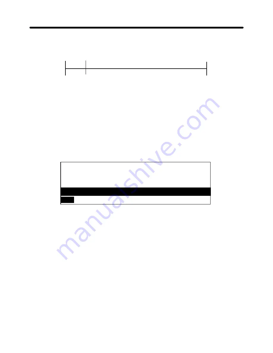
The following printing pattern is printed:
•
•
The serial number is printed on the first line (if it was entered), and then 59 lines of
characters are printed at 64 characters per line; with each line beginning with one
character from the right of the previous line.
•
If the CANCEL is pressed while the serial number input screen is displayed, the input
character string will not be registered as a serial number and display will return to the
Main Menu screen.
•
If the SPACE BAR or CANCEL key is pressed during printing, self printing is
suspended and the pop-up screen shown below is displayed:
[YES]
OK to cancel printing?
Use cursor to select and press RETURN.
[NO]
•
If RETURN is entered while the cursor is located at "YES", self-printing is canceled and
the display returns to the Main Menu.
•
If RETURN is pressed while the cursor is located at "NO", self-printing is resumed.
LM
RM
1 inch
6.4 inches
[Memory Codes 21(H) to 7E(H) printed]
Summary of Contents for DP-550CJ
Page 15: ...THEORY SERVICE MANUAL Mechanical 1 3 Fig 1 2 General View of Printing Mechanism ...
Page 20: ...THEORY Mechanical SERVICE MANUAL 1 8 Fig 1 7 Printer Flat Cable to Cartridge Alignment ...
Page 21: ...THEORY SERVICE MANUAL Mechanical 1 9 Fig 1 8 Ink Jet Cartridge to Flat Cable Alignment ...
Page 33: ...THEORY SERVICE MANUAL Mechanical 1 21 Fig 1 17 LCD Unit Installation in the Upper Cover ...
Page 34: ...THEORY Mechanical SERVICE MANUAL 1 22 DP 525CJ LW 800ic Fig 1 18 LCD of DP 525CJ LW 800ic ...
Page 38: ...THEORY Electrical SERVICE MANUAL 2 2 Fig 2 1 Major Electronic Component Parts ...
Page 80: ...REPAIR SERVICE MANUAL Troubleshooting 3 17 Fig 3 5 Results of Self Print Test ...
Page 118: ...REPAIR SERVICE MANUAL Mechanical 4 3 Fig 4 2 Removing the Sub Paper Support and Paper Support ...
Page 124: ...REPAIR SERVICE MANUAL Mechanical 4 9 Fig 4 6 Removing the LCD Unit ...
Page 127: ...REPAIR Mechanical SERVICE MANUAL 4 12 DP 525CJ LW 800ic Fig 4 8 Removing the LCD PCB 1 ...
Page 128: ...REPAIR SERVICE MANUAL Mechanical 4 13 DP 530CJ LW 810ic Fig 4 9 Removing the LCD PCB 2 ...
Page 129: ...REPAIR Mechanical SERVICE MANUAL 4 14 LW 810icBL Fig 4 10 Removing the LCD PCB 3 ...
Page 130: ...REPAIR SERVICE MANUAL Mechanical 4 15 DP 540CJ Fig 4 11 Removing the LCD PCB 4 ...
Page 131: ...REPAIR Mechanical SERVICE MANUAL 4 16 DP 550CJ LW 840ic Fig 4 12 Removing the LCD PCB 5 ...
Page 134: ...REPAIR SERVICE MANUAL Mechanical 4 19 Fig 4 14 Installing LCD Latch ...
Page 139: ...REPAIR Mechanical SERVICE MANUAL 4 24 Fig 4 18 Installing the Hinge Assy ...
Page 154: ...REPAIR SERVICE MANUAL Mechanical 4 39 Fig 4 30 Removing the Hopper Assembly ...
Page 162: ...REPAIR SERVICE MANUAL Mechanical 4 47 Fig 4 38 Removing the Carriage ...
Page 171: ...REPAIR Mechanical SERVICE MANUAL 4 56 Fig 4 45 Measuring Friction during Carriage Movement ...
Page 178: ...REPAIR Mechanical SERVICE MANUAL 5 2 Fig 5 1 Carriage Assembly Lubrication Points ...
Page 179: ...REPAIR SERVICE MANUAL Mechanical 5 3 Fig 5 2 Paper Feed Assembly Lubrication Points ...
Page 194: ...Feb 98 53T010BE1 R ...


