Brother DCP-6690CW Service Manual Download Page 287

6-106

Confidential

6.2

LUBRICATION

Apply the specified lubricants to the lubrication points as shown below.
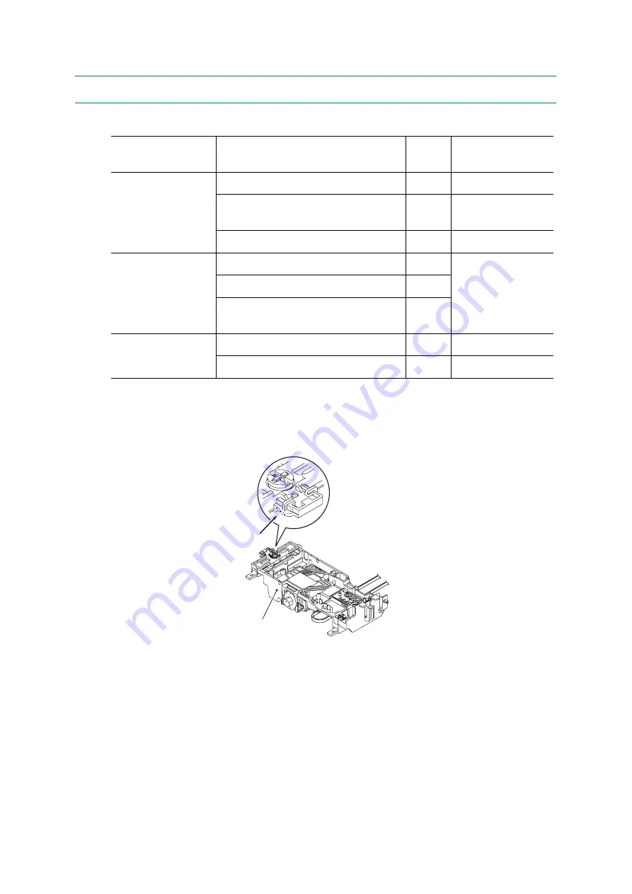
„

Head/carriage unit

Apply a 1 mm diameter ball of grease (Permalub BAN-5) to the lubrication points below.

Lubricant type

(Manufacturer)

Lubrication points

No. of

points

Lubricant amount

 per point

Permalub BAN-5
(Nippon Koyu)

Head/carriage unit

3

1 mm diameter ball

Motor plate and CR guide rail (bottom 
edges)

4

1 mm diameter ball

Switching lever guide

1

3 mm diameter ball

FLOIL BG1319
(Kanto Kasei)

CR guide rail (upper face)

11

2 mm diameter ball

CR support chassis (upper face)

11

CR support chassis (front and rear 
sides of upright rear edge)

28

Molykote EM-30LP
(Dow Corning)

Paper pull-in idle gear

1

3 mm diameter ball

Paper pull-in roller L 

2

1 mm diameter ball

Head/carriage unit

(6_84)

Apply grease here.

Summary of Contents for DCP-6690CW

Page 1: ...CP MFC SERVICE MANUAL MODELS DCP6690CW MFC6490CW MFC6890CDW April 2008 SM FAX089 8CAF11 3 Read this manual thoroughly before maintenance work Keep this manual in a convenient place for quick and easy reference at all times ...

Page 2: ... PageManager is a registered trademark of NewSoft Technology Corporation Microdrive is a trademark of International Business Machines Corporation CompactFlash is a registered trademark of SanDisk Corporation Memory Stick is a registered trademark of Sony Corporation SanDisk is a licensee of the SD and miniSD trademarks xD Picture Card is a trademark of Fujifilm Co Ltd Toshiba Corporation and Olymp...

Page 3: ...ce personnel must adequately understand and apply this manual The table below shows the functional comparison between the models covered by this manual This manual describes the models and their versions destined for major countries The specifications and functions are subject to change depending upon each destination Model DCP6690CW MFC6490CW MFC6890CDW RAM 64 MB LCD with backlight 4 2 inch wide ...

Page 4: ...d troubleshooting procedures This will help service personnel pinpoint and repair defective components CHAPTER 5 HANDLING DATA HELD IN THE MACHINE PRIOR TO REPAIR Describes how to handle data held in the machine to be repaired At the user site if the machine cannot print FAX data received and left in the machine due to the printing mechanism defective the service personnel should instruct the end ...

Page 5: ...ading Labels Shows the location of labels put on some parts and describes the coding information for serial number property data and manufacturing information Appendix 2 Firmware Installation Provides instructions on how to change firmware stored in the flash ROM on the main PCB or load firmware to a new main PCB from the host PC Appendix 3 EEPROM Customizing Codes Provides instructions on how to ...

Page 6: ...ppendix 6 Circuit Diagrams Provides the circuit diagrams of the MJ PCB and power supply PCB Appendix 7 Deletion of Personal Information Provides instructions on how to delete personal information recorded in the machine ...

Page 7: ...v Confidential SAFETY PRECAUTIONS Symbols used in the documentation ...

Page 8: ...vi Confidential ...

Page 9: ...vii Confidential ...

Page 10: ...viii Confidential ...

Page 11: ...ix Confidential ...

Page 12: ...x Confidential ...

Page 13: ...xi Confidential ...

Page 14: ...Confidential CHAPTER 1 PARTS NAMES AND FUNCTIONS ...

Page 15: ...s and names of components and describes their functions Information about the keys on the control panel is included to help you check operation or make adjustments CONTENTS 1 1 OUTLINE 1 1 1 2 CONTROL PANEL 1 3 1 3 COMBINATIONS OF TWO KEYS FOR SPECIAL FUNCTIONS 1 11 1 4 COMPONENTS 1 12 ...

Page 16: ...ay 1 for duplex print models 2 MFC only frontview 4 Media slots for 10 Scanner cover Scanner unit 1 ADF document cover ASSY 2 Control panel 3 Ink cartridge cover 8 Telephone line jack 2 5 Paper tray 1 1 6 Paper tray 2 7 Port for PictBridge 9 External telephone line jack 2 PhotoCapture Center USB flash memory drive ...

Page 17: ...into the machine sheet by sheet 6 Paper tray 2 Only for plain paper Load paper here Paper will be fed into the machine sheet by sheet 7 Port for PictBridge USB flash memory drive Connect a digital camera with PictBridge to this connector using the USB cable Insert a USB flash memory drive here 8 Telephone line jack 2 Plug in the modular plug on the telephone line here 9 External telephone line jac...

Page 18: ...1 3 Confidential 1 2 CONTROL PANEL DCP6690CW 5 6 4 1 2 3 ...

Page 19: ...1 4 Confidential ...

Page 20: ...1 5 Confidential MFC6490CW 10 9 7 8 6 1 2 3 4 5 ...

Page 21: ...1 6 Confidential ...

Page 22: ...1 7 Confidential ...

Page 23: ...1 8 Confidential MFC6890CDW 8 7 6 1 2 3 4 5 ...

Page 24: ...1 9 Confidential ...

Page 25: ...1 10 Confidential ...

Page 26: ...of keys Available for Displaying the firmware version Models with numerical keypad on the control panel Scan Stop Exit Models without numerical keypad on the control panel Alternative to the Menu key on the touch panel Scan Copy Models with touch panel This function is useful when the touch panel is inoperable Switching the software keypad between numerical and function keypads Scan Copy Models wi...

Page 27: ...gistration sensor harness unit Flushing box Front cover Lower cover Outer back cover Inner back cover Sub inner back cover LT cover Power supply PCB MJ PS shield unit Paper tray ASSY 1 3 Ink absorber box Main PCB ASSY Ink refill ASSY Maintenance unit Ink cartridge cover Media module cover WLAN PCB COMPONENTS_BHM9_Duplex MJ PCB 1 Paper tray ASSY 2 DCP DX paper tray ASSY 1 2 Duplex unit 2 DX inner c...

Page 28: ...Confidential CHAPTER 2 SPECIFICATIONS ...

Page 29: ...hapter lists the specifications of each model which enables you to make a comparison of different models CONTENTS 2 1 GENERAL 2 1 2 1 1 General Specifications 2 1 2 1 2 Paper Specifications 2 3 2 1 3 Printable Area 2 5 2 2 SPECIFICATIONS LIST 2 6 ...

Page 30: ...th touch panel 4 2 inch wide color LCD Operating Environment Temperature 10 to 35ºC Humidity 20 to 80 Best Print Quality 68ºF to 91ºF 20ºC to 33ºC Power Source U S A Canada 100 to 120 VAC EU 220 to 240 VAC 50 60 Hz Power Consumption Operating Standby Power save sleep Off mode DCP6690CW 26 W or less 6 W or less 4 0 W or less 0 7 W or less MFC6490CW U S A Canadian models 28 W or less 6 W or less 4 0...

Page 31: ...nd paper tray flap opened MFC6890CDW 540 x 488 x 323 mm 21 3 x 19 2 x 12 7 inches 574 x 611 x 323 mm 22 6 x 24 1 x 12 7 inches With document stopper and paper tray flap opened Weight DCP6690CW MFC6490CW 15 6 kg 34 4 lb MFC6890CDW 16 5 kg 36 4 lb excluding ink cartridges and accessories 22 6 in 21 3 in 574 mm 540 mm 21 4 in 19 2 in 543 mm 488 mm 12 7 in 323 mm 22 6 in 21 3 in 574 mm 540 mm 21 4 in ...

Page 32: ...Plain BP60PLGR USA only A3 Plain BP60PA3 Ledger Glossy Photo BP71GLGR A3 Glossy Photo BP71GA3 Letter Plain BP60PL100 USA only A3 Inkjet Matte BP60MA3 Letter Glossy Photo BP71GLTR A4 Plain BP60PA Letter Inkjet Matte BP60ML USA only A4 Glossy Photo BP71GA4 4 x 6 in Glossy Photo BP71GP A4 Inkjet Matte BP60MA 10 x 15 cm Glossy Photo BP71GP ...

Page 33: ...2 4 Confidential 1 Up to 100 sheets for paper of 80 g m2 20 lb 2 Up to 250 sheets for paper of 80 g m2 20 lb 3 BP71 260 g m2 69 lb paper designed for Brother inkjet machines ...

Page 34: ...2 5 Confidential 2 1 3 Printable Area Top 1 Bottom 2 Left 3 Right 4 Cut Sheet 0 12 in 3 mm 0 12 in 3 mm 0 12 in 3 mm 0 12 in 3 mm Envelopes 0 47 in 12 mm 0 95 in 24 mm 0 12 in 3 mm 0 12 in 3 mm ...

Page 35: ...2 6 Confidential 2 2 SPECIFICATIONS LIST DCP6690CW MFC6490CW 1 8 ...

Page 36: ...2 7 Confidential 2 8 ...

Page 37: ...2 8 Confidential 3 8 ...

Page 38: ...2 9 Confidential 4 8 ...

Page 39: ...2 10 Confidential 5 8 ...

Page 40: ...2 11 Confidential 6 8 ...

Page 41: ...2 12 Confidential 7 8 ...

Page 42: ...2 13 Confidential 8 8 ...

Page 43: ...2 14 Confidential MFC6890CDW 1 10 ...

Page 44: ...2 15 Confidential 2 10 ...

Page 45: ...2 16 Confidential 3 10 ...

Page 46: ...2 17 Confidential 4 10 ...

Page 47: ...2 18 Confidential 5 10 ...

Page 48: ...2 19 Confidential 6 10 ...

Page 49: ...2 20 Confidential 7 10 ...

Page 50: ...2 21 Confidential 8 10 ...

Page 51: ...2 22 Confidential 9 10 ...

Page 52: ...2 23 Confidential 10 10 ...

Page 53: ...Confidential CHAPTER 3 THEORY OF OPERATION ...

Page 54: ...4 Ink cartridges 3 20 5 Ink refill assembly 3 23 6 Ink supply tubes 3 24 3 2 2 2 Head maintenance mechanism 3 25 1 Overview 3 25 2 Maintenance unit components 3 26 3 Mechanisms constituting the head maintenance mechanism 3 28 4 Power transmission route to the head maintenance mechanism and motor rotational direction 3 33 5 Purge types ink usage purge counts and purge codes 3 36 6 Ink cartridge cap...

Page 55: ...Paper feeding mechanism Power supply Host Compact Flash Memory Stick SD Memory Card xD Picture Card Paper feed motor ASF motor LAN interface LAN WLAN Control panel 3 3 2 Overview_BHM9_E Backup battery MJ PCB Line Scanner unit CIS unit CIS motor Speaker ADF unit ADF motor SDAA Digital camera with PictBridge USB interface 1 USB flash memory drive Ink jet printer unit Head carriage unit Carriage PCB ...

Page 56: ...encoders PF encoder ASF encoder and CR encoder various sensors and two thermistors Scanner Mechanism Printing Mechanism Ink supply and ink jet mechanism head maintenance mechanism and carriage drive mechanism Left Right Document path for ADF scanning BH9_ADF_Scanner_1 Document for flat bed scanning Front Rear Carriage drive mechanism Ink supply and ink jet mechanism Head maintenance mechanism 3_01...

Page 57: ...tray 1 for duplex print models Duplex print mechanism for duplex print models Recording paper path 3_02_BH9_E Recording paper path in paper tray 1 Recording paper path in paper tray 2 Front Rear 3_02_Duplex Front Rear Path for bottom face print Path for top face print Recording paper path ...

Page 58: ...d ejecting mechanisms See Section 3 2 2 4 ASF motor 1 DC motor Paper feed motor DC motor Duplex print mechanism 2 See Section 3 2 2 5 ASF motor 1 DC motor Paper feed motor DC motor Encoders See Section 3 2 3 Paper feed motor encoder PF encoder ASF motor encoder ASF encoder Carriage motor encoder CR encoder Sensors See Section 3 2 3 Document front sensor Document rear sensor Document width sensor S...

Page 59: ...e shows the components making up the ADF document pull in roller document separation roller document feed rollers document ejection rollers ADF motor document front and rear sensors and document width sensor For further details on the sensors see Section 3 2 3 Document cover ADF unit ADF document cover ASSY Scanner top cover CIS drive belt CIS flat cable Scanner base CIS idle pulley CIS rail 3_03 ...

Page 60: ...inch rollers Document width sensor actuator Document front sensor actuator ADF motor Document feed rollers Left Right Document pressure roller 1 Document separation roller Document pull in roller Document ejection rollers Document path for ADF scanning Document support BH9_ADF_Scanner_2 Document for flat bed scanning ...

Page 61: ...es the machine face down onto the document cover The machine ejects subsequent pages above this one to preserve the document page order 2 Flat bed scanning CIS unit moves under stationary document The user lifts the document cover places a page or open book face down with the left and top edges fitting on the left and top guidelines on the glass plate and closes the document cover The CIS drive me...

Page 62: ...nges on the ink To keep the optimum head performance the head maintenance mechanism shown on page 3 35 uses the rotational torque of the ASF motor 1 to cap the head nozzles in order to prevent them from drying up It also uses the rotational torque of the paper feed motor to purge for removing air bubbles from the head carriage unit and wipe off any ink remaining on the head nozzle surface The carr...

Page 63: ...m of the maintenance unit In duplex print models this motor also drives the duplex print mechanism to switch back the recording paper for bottom face printing Clutch gears L and R shown on page 3 42 Clutch gear L switches the transmission route of the ASF motor rotation between the paper pulling in mechanism and the head capping carriage lock mechanisms In duplex print models clutch gear L also sw...

Page 64: ...back paper path The SB paper in the DX paper tray 1 is fed again and printed on its bottom face If a paper jam occurs in the switchback paper path the user takes the DX paper tray 1 out of the machine and opens the DX cover by pulling up the DX cover open levers green in color provided on both sides in front of the duplex unit to remove the jammed paper After completion of duplex printing the dupl...

Page 65: ...ge unit below The four ink cartridges black yellow cyan and magenta are mounted on the ink refill assembly For further details see 4 Ink cartridges below The ink refill assembly secures the ink cartridges and connects them to the corresponding ink supply tubes For further details see 5 Ink refill assembly below The ink supply tubes supply the head carriage unit with ink fed from the ink cartridges...

Page 66: ...k both air and ink through the ink supply tubes Leaving too long interval between this priming and actual use however risks air bubbles increased viscosity and other quality issues with the ink in the supply tubes Before using this machine for the first time therefore this machine automatically replaces the ink supply path contents with fresh ink using an initial purge a repeat of this priming ope...

Page 67: ...es however because of the nature of piezoelectric materials fluctuation in manufacturing accuracy and other factors The front end therefore leaves the production line with head property labels giving property data The manufacturer writes this property data to the EEPROM on the main PCB incorporating this unit Based on the property data of the front end the processor drives piezoelectric ceramic ac...

Page 68: ...n materials from the ink Metal plates These form the head nozzle pressure chambers ink flow paths and manifolds Nozzle plate This plate has a total of 470 nozzles 47 nozzles x 2 lines staggered x 5 rows black x 2 yellow cyan and magenta Head driver This flexible circuit board holds the piezoelectric driver chip Nozzle array head bottom plate viewed from the bottom Magenta Cyan Paper feed direction...

Page 69: ...perpendicular to that surface Drive signals removing this voltage for specific channel electrodes allow the piezoelectric elements to return to their original shape sucking ink into the corresponding channels Reapplying the bias voltage stretches the elements once again applying pressure to the ink spraying it from the head nozzle The ink drop hits the paper on the platen forming a dot Pressure ch...

Page 70: ... or lowering the pressure in the right chamber Air vent unit At regular scheduled intervals this vents any air bubbles that have accumulated in the damper assemblies The air vent rods in the maintenance unit push up the shut off valves opening the air vent flow paths Damper ASSY Yellow Shut off valves Air vent unit Air vent cap Damper ASSY Cyan Damper ASSY Black Damper ASSY Magenta Right chamber R...

Page 71: ...id ink contains trace amounts of air These molecules coalesce into air bubbles as the piezoelectric ceramic actuators vary the pressure on the ink in the ink jet head channel See the illustration on page 3 14 Removing as many of these bubbles as possible before the ink reaches the ink jet head is essential to maintaining proper print quality The above illustration shows how the damper assemblies p...

Page 72: ...the bubble is always constant but the boundary surface area decreases or increases when the bubble contracts or expands respectively That is when the pressure becomes high the bubble contracts so that the amount of air moving from the bubble to the ink decreases in proportion to the boundary surface area decreased On the contrary when the pressure becomes low the bubble expands so that the amount ...

Page 73: ...ctuators and thus degrading ink jet performance The above illustration shows an example of an extremely large air bubble reaching the head nozzle from the channel ink flow path the dotted line the changes resulting from applying a voltage to the laminated electrode expanding the piezoelectric ceramic actuator Note how contraction of the air bubble absorbs the pressure from the piezoelectric cerami...

Page 74: ...turing process prevents such air bubbles with a step deaeration that removes air from the ink before injection into the cartridge Vacuum packaging then prevents air contamination during shipping and storage Pigment based ink This machine uses dye based inks for colors and pigment based ink for black Using the pigment based black ink reduces fuzziness from print character outlines boosts resolution...

Page 75: ...y may open not only the disc valve S but also the disc valve D ink supply port at almost the same timing causing backflow of ink from the ink supply port The backflow of ink could temporarily affect the performance of the ink jet mechanism so conventional machines automatically perform a purge operation after replacement of an ink cartridge To prevent the backflow of ink a new ink cartridge has a ...

Page 76: ...is a float When there is ink in the cartridge buoyancy lifts the float rotating the sensor actuator about a pivot near the center of the actuator to block the light beam to the ink empty sensor indicating that there is ink As the ink level in the ink cartridge drops however the float falls eventually moving the sensor actuator out of the beam Light hitting the sensor outputs the ink near empty sig...

Page 77: ...ill assembly Ink refill case Ink empty sensor PCB Ink empty sensors Cartridge release levers 3_07 Ink refill base 3_08 Ink foam case Ink cartridge detection sensor PCB Ink cartridge detection sensors Ink foam Ink refill base foam ...

Page 78: ...ed An ink empty sensor actuator blocking the light beam to an ink empty sensor indicates that there is ink in the ink cartridge When ink runs low the actuator moves out of the beam activating the sensor Ink near empty and showing the Ink low message If any of the ink cartridges is replaced with the one having different ink volume when the machine power is OFF the corresponding ink cartridge detect...

Page 79: ...enance unit has the following mechanisms Head capping mechanism See page 3 28 Carriage lock mechanism See page 3 28 Purge mechanism See page 3 29 Air removing mechanism See page 3 31 Head wiper mechanism See page 3 32 The ink absorber box absorbs the ink sucked out by purge operations Engine unit Paper feed motor Head carriage unit Flushing box Ink supply tubes Ink refill assembly Ink absorber box...

Page 80: ...t it tightly over the print head to seal the head nozzles The had cap holder is driven by the ASF motor Carriage lock This is a part of the head cap holder It locks the head carriage unit in its home position so that the head cap unit protects the head nozzles Purge gear and purge bevel gear These gears transmit the rotational torque of the paper feed motor via the clutch gear R to the planetary a...

Page 81: ...mospheric pressure Air vent cap and rods The air vent cap and rods remove air bubbles trapped in the damper assemblies in the back end of the head carriage unit During air venting with the tube pump the air vent cap fits tightly over the air vent unit in the head carriage unit so that the negative pressure applies to the air vent unit Pushing up the air vent rods opens the shut off valves inside t...

Page 82: ...r L engages with the cap lift cam gear purge mode Driving the ASF motor rotates the cap lift cam so that the cap lift arm raises the head cap holder fitting it tightly over the head nozzle surface 2 Carriage lock mechanism This mechanism locks the head carriage unit to prevent the head nozzles from getting out of the head cap unit accidentally due to external vibration or impact when the machine i...

Page 83: ...n position Next the paper feed motor reverses to activate the tube pump producing negative pressure to drain the air and old ink from the head nozzles and channels into the ink absorber box Purge cam Pump switching unit Purge bevel gear Main drain tube Tube pump Planetary arm Air vent tube Main drain tube Black drain tube Color drain tube Main drain tube 3_14 Cap lift cam gear ASF changeover gear ...

Page 84: ... atmospheric pressure 3 2 Draining ink The tube pump consists of a pump gear and tube roller As the pump gear rotates the tube roller on its circumference squeezes the main drain tube looped around the pump gear forcing its content toward the ink absorber box and creating negative pressure For details about the power transmission route to the head maintenance mechanism see 4 below Head cap for bla...

Page 85: ...ve pressure from the tube pump removes air trapped in the damper assemblies Purge gear Maintenance unit Air vent rod for black ink Air vent rods for color ink Air vent cap Slide cam for color ink Purge cam Slide cam for black ink 3_16 Cap lift cam gear ASF changeover gear Damper ASSY Yellow Shut off valves Air vent unit Air vent cap Damper ASSY Cyan Damper ASSY Black Damper ASSY Magenta Right cham...

Page 86: ...ter the purge operation the purge cam pushes up the head wiper wiping off any ink remaining on the head nozzle surface as the head carriage unit moves from right to left Head wiper Purge cam 3_15 Purge gear Cap lift cam gear ASF changeover gear ...

Page 87: ... and carriage lock mechanisms See page 3 35 for the related components In duplex print models if the ASF motor rotates counterclockwise the rotational torque is transmitted via the gear trains in the link gear holders to the duplex print mechanism For details refer to Section 3 2 2 5 Paper feed motor Maintenance unit purge air removing and head wiper mechanisms As shown on the next page the paper ...

Page 88: ...r 3_20 Opening tube to the atmospheric air Paper feed roller ASF changeover gear Idle gear 16 ASF maintenance drive gear Always engaged with PF roller gear R Mode switching lever PF roller gear R Purge bevel gear Purge gear Planet gear Cap lift cam gear Paper feed roller Front ASF motor holder ASSY Paper feed motor PF roller gear L 3_17 PF roller gear R Clutch gear L Clutch gear R ASF motor Mainte...

Page 89: ...er ASF motor holder ASSY Air vent cap Air vent rods Head wiper Cap lift cam Cap lift cam gear ASF changeover gear Air cap stopper For duplex print models only ASF motor gear Cap lift cam Purge gear Purge bevel gear Tube pump Planetary arm Purge cam Cap lift cam gear ASF changeover gear Clutch gears L R Idle gear 16 ASF maintenance drive gear 3_18 Pump switching unit Planet gear ASF motor holder AS...

Page 90: ... ink cartridge listed above are typical values under ordinary conditions Note Values given in the above tables are as of November 2008 Ink Cartridge Type Contents Usable Portion 1 Starter and bundled cartridges Black ink cartridge High yield type 23 05 ml 21 11 0 25 ml Color ink cartridges 10 10 ml 8 59 0 25 ml Spare ink cartridges Black ink cartridge High yield type 23 05 ml 21 11 0 25 ml Standar...

Page 91: ...r on the top of the head carriage unit scans the CR encoder strip above the CR support chassis to monitor the current head position relative to the home position The controller uses this signal for robust control ensuring uniform speed The CR encoder strip is a clear film striped in a 1 150 inch cycle It offers a choice of three travel speeds of the head carriage unit 57 7 43 3 and 21 7 ips to mat...

Page 92: ...head carriage unit to the CR support chassis The rib acts as a pivot for the slider s damping springs pressing the head carriage unit to the rear Slider L has a head skew adjuster knob that shifts the slider back and forth adjusting the angle of this backward pressure Rotating the head skew adjuster knob tilts the entire head carriage unit thus adjusting the head nozzle vertical angle relative to ...

Page 93: ...witched by hitting against the stoppers at the right and left ends of the CR guide rail and CR support chassis For thick paper and envelopes and other types of paper The machine adjusts the distance from the platen to the head carriage unit to 2 3 mm for thick paper and envelopes and 1 6 mm for other types of paper in order to keep the distance a constant For thick paper and envelopes For other ty...

Page 94: ...etting on the machine controls the slider cams to determine the height of the head carriage unit Controlled by Adjustment for Thick paper and envelopes Other types of paper Printer driver in printing from the PC Yes Yes Paper type setting in copying and printing via PhotoCapture Center No Yes ...

Page 95: ...machine supports three paper feed modes normal SF mode high speed feed mode and LT mode Depending upon the selected print quality and paper tray any of those three modes applies as listed below 1 DX paper tray 1 for duplex print models Print quality Fast Normal Other quality Paper tray 1 1 High speed feed mode Normal SF mode Paper tray 2 LT mode Front Paper tray 1 1 Paper tray 2 Paper ejection rol...

Page 96: ...paper feed motor is transmitted via the PF roller gear L to the paper feed roller that advances paper to the printing start position 1 DX paper tray 1 for duplex print models 2 Link gear holder LT DX ASSY for duplex print models Right position Purge mode Left position ASF mode Mode switching lever ASF motor Idle gear 16 Idle gear 15 Clutch gear L ASF changeover gear ASF idle gears 17 Paper pull in...

Page 97: ...at rotates in the forward direction to eject the paper printed High speed feed mode Paper tray 1 1 1st stage Just as in the normal SF mode the clockwise rotation of the ASF motor pulls in a sheet of paper loaded in paper tray 1 1 The difference from the normal SF mode is that the paper feed motor also rotates clockwise at the same time as the ASF motor The paper feed roller rotates in the forward ...

Page 98: ...he LT idle gear 15 and gear 39 to the gear train in the link gear holder LT ASSY 2 The rotation is further transmitted via the LT related components to the LT paper pull in rollers that rotate in the forward direction to pull in a sheet of paper loaded in paper tray 2 The paper feed motor also rotates counterclockwise at the same time as the ASF motor to rotate the paper feed roller in the backwar...

Page 99: ...precision paper positioning during printing This signal also determines the motor parameters for rapidly and precisely positioning the paper Fixed speed paper feed This operation rotates the paper feed roller to feed the paper at a constant speed regardless of load fluctuations The primary application is ejecting paper when printing is complete in other words in situations where precision stop pos...

Page 100: ... driven by the ASF motor The rotational torque is transmitted via the gear trains in the link gear holder DX ASSY and link gear holder LT DX ASSY to the DX cam whose inner profile drives the DX flapper horizontal backward tilted positions via the DX flapper drive lever For details refer to the next page The SB roller drive mechanism is driven by the paper feed motor whose rotational torque is tran...

Page 101: ...the DX flapper drive lever pivots the DX flapper up horizontal position and down backward tilted position Torque transmission route from the ASF motor to the DX flapper DX cam Paper ejection roller SB gear SB gear A SB gear B DX cam switch SB gear C SB clutch lever DX cam shaft DX flapper drive lever Duplex unit DX flapper DX gear 18 DX gear 25 18 DX cam shaft gear Planet gear in the link gear hol...

Page 102: ... does not rotate 3_Duplex_3 DX cam Paper ejection roller SB gear SB gear A SB gear B SB gear C SB gear D SB clutch lever DX cam shaft DX cam shaft gear Planet gear in the link gear holder LT DX ASSY ASF motor Cap lift cam gear Link gear holder DX ASSY Duplex unit SB roller SB roller drive gear Switchback paper detection sensor actuator DX gear 18 DX gear 25 18 Paper ejection roller shaft Paper fee...

Page 103: ...backward direction counterclockwise to switch back the paper through the switchback paper path toward the DX paper tray 1 Then the machine feeds the switchbacked paper SB paper by driving not only the paper pull in rollers clockwise but also the SB roller counterclockwise concurrently The concurrent drive surely brings the SB paper to the paper pull in rollers preventing the paper pull in rollers ...

Page 104: ...der the star wheels on the CR support chassis In duplex printing the machine performs backward registration for the SB paper After the SB paper is fed to the platen by the concurrent drive of the paper pull in rollers clockwise and the paper feed roller counterclockwise the paper feed roller rotates clockwise to feed the paper back until its leading edge becomes released from the paper feed roller...

Page 105: ...s printing It also protects the platen from no paper printing when a paper jam occurs preventing stains on the platen and the back side of paper Sensor Name Sensor Type Location Document front sensor Photosensor On the document sensor PCB in the ADF unit Document rear sensor Photosensor Document width sensor Photosensor On the document width sensor PCB in the ADF unit Scanner cover sensor Carbon s...

Page 106: ...hback paper detection sensor detects in duplex printing whether there is a recording paper in the switchback paper path The DX cover sensor detects whether the DX unit cover is properly closed The DX cam switch turns ON or OFF depending on the position of the DX cam that drives the DX flapper The casing internal temperature thermistor monitors the temperature inside the machine With this thermisto...

Page 107: ...carbon switch that consists of a carbon on the rubber keypad and a carbon contact printed on the control panel PCB Opening the scanner cover or the ink cartridge cover releases the corresponding sensor actuator so that the actuator is pressed against the rubber keypad by the spring force Accordingly the carbon on the rubber keypad comes into contact with the carbon contact on the control panel PCB...

Page 108: ...ion sensor actuator DX cam switch Switchback paper detection sensor Switchback paper detection sensor PCB CR encoder strip Head carriage unit 3_27 Ink empty sensors Ink cartridge detection sensors Ink cartridge detection sensor PCB Ink cartridge cover sensor actuator Control Panel PCB Scanner cover sensor actuator Purge cam switch DX cover sensor Maintenance unit ASF encoder sensor PCB ASF encoder...

Page 109: ...e 2 wire 5 wire 5 wire PictBridge USB Registration sensor 4 wire 3 wire Digital camera USB flash memory drive Casing internal temperature thermistor 3 6 wire 4 2 wire 2 wire MJ PCB Line External telephone SDAA DC motor driver DC motor driver 7 wire Ink cartridge detection sensor PCB Document front sensor CIS unit 2 wire Speaker Document sensor PCB BlockDiagram_BHM9_E LAN LAN I F PC USB WLAN WLAN P...

Page 110: ...Confidential CHAPTER 4 ERROR INDICATION AND TROUBLESHOOTING ...

Page 111: ...s 4 8 4 1 2 Communications Errors For MFC only 4 30 4 2 TROUBLESHOOTING 4 37 4 2 1 Introduction 4 37 4 2 2 Precautions 4 37 4 2 3 Checking Prior to Troubleshooting 4 37 4 2 4 Troubleshooting Based on Problem Type 4 39 1 Control panel and LCD problems 4 39 2 FAX problems For MFC only 4 39 3 Communications problems For MFC only 4 39 4 Paper document feeding problems 4 40 5 Print image problems 4 41 ...

Page 112: ...e and purge mechanisms 4 54 4 Print head mechanism 4 55 5 Duplex print mechanism 4 56 6 Sheet feeder SF mechanism 4 56 7 Paper feeding mechanism 4 57 8 Speaker 4 57 9 Control panel 4 57 10 PCBs 4 58 11 Adjustments data in the memories 4 59 ...

Page 113: ...ipment Errors If an equipment error occurs the machine emits an audible alarm five short beeps twice and shows the error message on the LCD For the error messages see 1 below To display detailed error information use Function code 82 described in Chapter 9 Section 9 4 27 that is make the machine enter the maintenance mode and then press the 8 and 2 keys Following the MACHINE ERROR one of the error...

Page 114: ...4 2 Confidential 1 Error messages appearing on the LCD ...

Page 115: ...4 3 Confidential For MFC only ...

Page 116: ...4 4 Confidential For MFC only ...

Page 117: ...4 5 Confidential For MFC only ...

Page 118: ...4 6 Confidential ...

Page 119: ...4 7 Confidential ...

Page 120: ...06 07 08 09 0A 0B 0C DX cam switch ON OFF detection failure DX cam malfunction Error in duplex printing with the Paper Jam on the LCD Too much ink used for top face printing had made the paper curly or wavy so that switchbacking the paper caused a paper jam in the switchback paper path Pull out the DX paper tray 1 open the DX cover and remove the jammed paper Open the outer back cover and the inne...

Page 121: ...d the inner back cover DX and remove the jammed paper Open the scanner cover and remove the jammed paper Paper temporarily ejected after top face printing was removed before switchback ing Open and close the scanner cover Switchback paper detection sensor defective Correct the connection of the switchback paper detection sensor harness to the main PCB Replace the duplex unit SB roller defective Re...

Page 122: ...ss unit Main PCB defective Replace the main PCB 0F In bottom face printing the switchback paper detection sensor does not go OFF even after the recording paper is fed for the specified period independent of the registration sensor or DX cam switch The Paper Jam appears on the LCD Misdetection of the recording paper length Pull out the DX paper tray 1 open the DX cover and remove the jammed paper O...

Page 123: ...ied range Set recording paper in correct size Switchbacked paper has dragged a new sheet of paper loaded in the DX paper tray 1 along the switchback paper path Reload paper Replace the base pads and tray flap pads in the DX paper tray 1 Paper width sensor media sensor defective Replace the carriage PCB ASSY Registration sensor defective Replace the registration sensor actuator Replace the inner ch...

Page 124: ...ed paper or foreign materials DX cam switch defective Correct the connection of the DX cam switch harness to the main PCB Replace the duplex unit DX flapper defective Replace the duplex unit 1B 1C Not used 1E 1F Not yet recovered from a paper jam Recovery requires opening and closing the DX cover and the scanner cover DX cover sensor defective Open and close the DX cover and the scanner cover Corr...

Page 125: ...k cartridge The ink cartridge loaded is not the specified one Load the specified ink cartridge Ink empty sensor defective Replace the ink refill ASSY Ink empty sensor PCB defective Main PCB defective Replace the main PCB 24 25 Not used 26 27 28 29 Insufficient ink detected Running out of ink 26 Black ink 27 Yellow ink 28 Cyan ink 29 Magenta ink Replace or reload the ink cartridge Ink empty sensor ...

Page 126: ...main PCB 3 except 3E Head carriage unit travel error Software malfunction Open and close the scanner cover Unplug and plug the AC cord Any obstacles on the travel path of the head carriage unit Clean and lubricate the CR guide rail and CR support chassis CR timing belt come off Set the CR timing belt into place CR encoder strip stained or scratched Replace the CR encoder strip Carriage PCB defecti...

Page 127: ...sing internal temperature thermistor has detected abnormal temperature in the machine Main PCB defective Replace the main PCB Casing internal temperature thermistor defective Replace the ink refill ASSY 41 Not used 42 The head drive voltage has not dropped from the high to low level within the specified period Piezoelectric ceramic actuator or head driver defective Replace the head carriage unit C...

Page 128: ... Head carriage unit broken Main PCB defective Replace the main PCB 45 Not used 46 The number of performed purge sequences has reached the limit The ink absorber box may be filled with drained ink Purge counter overflown Replace both the ink absorber box and flushing box and reset their counters When you need to replace the ink absorber box or flushing box replace both Refer to page 7 40 or page 9 ...

Page 129: ...he specified period in the self diagnosis Piezoelectric ceramic actuator defective Cracks or rare short Replace the carriage PCB ASSY Replace the head carriage unit Main PCB defective Replace the main PCB 50 51 The purge cam switch does not come ON or OFF even after the purge cam has been driven by the specified number of pulses Planetary arm assembly not engaged correctly Set the maintenance unit...

Page 130: ...applied to the purge cam Paper feed motor broken Replace the engine unit Main PCB defective Replace the main PCB 53 56 Not used 57 The head carriage unit does not return to the home position capping position Head cap unit head wiper or other parts on the maintenance unit interfering with the head carriage unit Set these parts back into place If any part on the maintenance unit does not operate smo...

Page 131: ... broken Paper feed motor defective Replace the engine unit PF roller gear L broken Engine unit defective Main PCB defective Replace the main PCB Power supply PCB defective Replace the power supply PCB 5C Not used 5D Current protection for the driver IC activated when the purge cam was being driven The driving current has exceeded the limit due to an abnormal load applied to the maintenance unit Re...

Page 132: ...in PCB 6D 6E Not used 6F ASF motor does not stop at the intended timing Malfunction caused by overload Open and close the scanner cover scanner unit Unplug and plug the AC cord Relevant motor harness not connected correctly Correct the connection ASF encoder sensor defective Replace the ASF motor ASSY ASF motor defective Main PCB defective Replace the main PCB 70 71 Cannot detect the ON OFF state ...

Page 133: ... defective Cap lift cam switch defective Replace the maintenance unit Main PCB defective Replace the main PCB 7B 7C Not used 7D Current protection for the driver IC activated when the cap lift cam was being driven Foreign materials in the head capping mechanism Remove foreign materials and clean the mechanism ASF encoder sensor defective Replace the ASF motor ASSY ASF motor defective Cap lift cam ...

Page 134: ...er smaller than the specified size loaded in the paper tray Load the correct size of paper Press the Color Start or Black Start key Paper width sensor not adjusted Adjust the margin for borderless printing with Function code 66 in the maintenance mode Paper width sensor defective Replace the carriage PCB ASSY Main PCB defective Replace the main PCB 82 Recording paper jam in paper pull in operation...

Page 135: ...he paper tray Reload paper Bank ASSY deformed Replace the bank ASSY Registration sensor actuator unhooked Set the registration sensor actuator into place Registration sensor actuator defective Replace the registration sensor actuator Main PCB defective Replace the main PCB Registration sensor defective Replace the PF encoder registration sensor harness unit Bank ASSY Paper Correct Wrong Bank ASSY ...

Page 136: ...otor defective Replace the engine unit The paper ejection roller does not rotate correctly Main PCB defective Replace the main PCB 85 87 Not used 88 Recording paper jam Even after paper pulling in operation the registration sensor is still OFF Outer back cover not closed correctly Close the outer back cover correctly Registration sensor harness not connected correctly Correct the connection Bank A...

Page 137: ...ed motor defective Replace the engine unit Main PCB defective Replace the main PCB 8B The paper feed motor stops suddenly Abnormal load applied to the paper feed roller PF related gear s broken Replace the PF related gear s PF encoder disk stained or scratched Replace the PF encoder disk PF encoder sensor defective Replace the PF encoder registration sensor harness unit Paper feed motor defective ...

Page 138: ... PCB A2 During scanning or ejecting a document of 90 cm or longer is detected Document jam Remove the jammed document Foreign materials in the machine Remove foreign materials Document rear sensor actuator caught on the surrounding parts Correct the surrounding parts on which the actuator caught Document rear sensor broken Replace the document sensor PCB Document ejection roller defective or not r...

Page 139: ...IS type mounted at repair Check the CIS type mounted and enter the new CIS type into the EEPROM with Function code 59 in the maintenance mode A8 Color parameter matching error Used for monitoring bugs at the factory Install the latest firmware A9 AE Not used AF CIS positioning error CIS flat cable broken or not connected properly Correct the cable connection Replace the scanner cover scanner unit ...

Page 140: ...ace the main PCB E3 Wireless LAN MAC address not registered WLAN PCB defective Replace the WLAN PCB E4 Not used E5 Not used Write error in EEPROM on the cordless PCB The base ID code and cordless handset ID code registered are mismatched Reregister the cordless handset ID code Replace the cordless handset Replace the cordless PCB E6 Write error in EEPROM Main PCB defective Replace the main PCB E7 ...

Page 141: ...e LCD flat cable not connected correctly Correct the connection LCD unit defective Replace the LCD unit Main PCB defective Replace the main PCB ED Touch panel initialization failure 2 at the time of power ON Touch panel in contact with something during initialization at the time of power ON Clean the touch panel then turn the machine off and then on again Touch panel defective Replace the LCD unit...

Page 142: ... only If a communications error occurs the machine emits an audible alarm intermittent beeping for approximately 4 seconds displays the corresponding error message and prints out the transmission verification report if the machine is in sending operation ...

Page 143: ...mote station in sending 11 10 Unobtainable tone detected after dialing 17 07 No response from the calling station in receiving Code 1 Code 2 Causes 20 01 Unable to detect a flag field 20 02 Carrier was OFF for 200 milliseconds or longer 20 03 Abort detected 1 in succession for 7 bits or more 20 04 Overrun detected 20 05 A frame for 3 seconds or more received 20 06 CRC error in answerback 20 07 Err...

Page 144: ...tion or its password switch OFF 32 11 Remote terminal not equipped with or not ready for confidential mailbox function 32 12 Remote terminal not equipped with or not ready for relay broadcasting function 32 13 No confidential mail in the remote terminal 32 14 The available memory space of the remote terminal is less than that required for reception of the confidential or relay broad casting instru...

Page 145: ...al recording width requested 40 05 ECM requested although not allowed 40 06 Polled while not ready 40 07 No document to send when polled 40 10 Nation code or manufacturer code not coincident 40 13 Polled by any other manufacturers terminal while waiting for secure polling 40 17 Invalid resolution selected 40 20 Invalid full color mode requested Code 1 Code 2 Causes 50 01 Vertical resolution capabi...

Page 146: ...ansmission reception Code 1 Code 2 Causes 63 01 Password plus lower 4 digits of telephone number not coincident 63 02 Password not coincident 63 03 Polling ID not coincident Code 1 Code 2 Causes 74 DCN received Code 1 Code 2 Causes 80 01 Fallback impossible ...

Page 147: ...cond time out A0 12 Receive buffer full during operation except receiving into memory A0 13 Decoding error continued on 500 lines A0 14 Decoding error continued for 10 seconds A0 15 Time out 13 seconds or more for one line transmission A0 16 RTC not found and carrier OFF signal detected for 6 seconds A0 17 RTC found but no command detected for 60 seconds AA 18 Receive buffer full during receiving ...

Page 148: ... polling even during turn around transmission due to call reservation B0 04 PC interface error BF 01 Communication canceled by pressing the STOP key before establishment of FAX communication BF 02 Communication canceled by pressing the STOP key after establishment of FAX communication BF 03 Transmission canceled due to a scanning error caused by no document or document feed problem in ADF scanning...

Page 149: ... the machine to discharge static electricity charged in your body When transporting PCBs be sure to wrap them in conductive sheets When replacing the head carriage unit put on a grounding wrist band and perform the job on a static mat Also take care not to touch the conductor sections on the flat cables After repairing the defective section be sure to check again if the repaired section works corr...

Page 150: ...aper is used 2 The recording paper is not dampened Ink cartridges 1 Check that all of four ink cartridges are loaded Head carriage unit 1 Repeat the purge operation Function code 76 several times Refer to Chapter 9 Section 9 4 24 2 Clean the print surface of the head carriage unit ...

Page 151: ...uch panel inoperative Adjust the touch panel with Function code 78 in the maintenance mode Refer to Chapter 9 Section 9 4 25 Touch panel harness Touch panel relay PCB in the LCD unit Main PCB Problem Check 1 No faxes will be able to be sent Rubber keypads Control panel PCB Main PCB MJ PCB 2 Speed dialing will not work Ordinary dialing function If it works normally check the main PCB if not refer t...

Page 152: ... parts 4 Document jam Document rear sensor actuator Foreign materials in the document path Sensors by using Function code 32 in the maintenance mode Refer to Chapter 9 Section 9 4 9 ADF motor Main PCB 5 Recording paper not fed Paper pull in roller holder Base pad in the paper tray Base pads and tray flap pads in the DX paper tray 1 1 Outer back cover PF related gears Duplex unit 1 Main PCB Paper f...

Page 153: ...lor Light Dark Straight vertical stripes Blurred vertical stripes White vertical streaks Ink splash Ink splash Print edges not aligned Random missing dots White horizontal streaks Stained leading edge of recording paper Overlappinglines over the whole page Separated lines over the whole page Overlapping lines at the trailing edge of the recording paper Separated lines at the trailing edge of the r...

Page 154: ...ation Check the connection of the head flat cables on the main PCB If either of those cables is broken or damaged replace it Check the head property data Refer to Chapter 9 Section 9 4 20 Replace the head carriage unit Replace the main PCB Clean the head caps and wiper of the maintenance unit with a Rubycel stick For the cleaning procedure refer to Chapter 8 Section 8 2 CLEANING THE MAINTENANCE UN...

Page 155: ...ral times to remove dust or air bubbles from its nozzles If the problem persists replace the head carriage unit Refer to Chapter 9 Section 9 4 24 Check the following components Ink cartridges Head carriage unit and carriage PCB ASSY Main PCB Power supply PCB Head property data Refer to Chapter 9 Section 9 4 20 Maintenance unit 6 Straight or blurred black or white vertical stripes Scanner Check the...

Page 156: ...gned Printer For duplex print models Change the special duplex copy settings using the steps below 1 Press Duplex Copy on the machine s panel 2 Press On to turn on the duplex setting 3 Press Advanced 4 Press DX1 or DX2 DX1 helps avoid paper jams when copying by allowing more time for the ink to dry DX2 allows more time for the ink to dry while also using less ink Check the alignment of vertical pr...

Page 157: ... the head carriage unit Check the paper feed related rollers Perform the print head skew compensation with the head skew adjuster knob Refer to Chapter 7 Section 7 2 4 Clean the head caps and wiper of the maintenance unit with a Rubycel stick For the cleaning procedure refer to Chapter 8 Section 8 2 CLEANING THE MAINTENANCE UNIT 11 Stained leading edge of recording paper Printer For duplex print m...

Page 158: ...oller and paper ejection roller with Function code 58 in the maintenance mode Refer to Chapter 7 Section 7 2 5 Correct the positioning error of the head carriage unit with Function code 63 in the maintenance mode Refer to Chapter 7 Section 7 2 4 Replace the PF encoder disk Replace the PF encoder registration sensor unit 15 Stains in the center of or over the whole page of the recording paper For d...

Page 159: ...rk interface Problem Action to be taken 1 No image data can be read Insertion direction of memory cards Insert a Compact Flash card SD Memory Card or xD Picture Card with the label side facing up Insert a Memory Stick card with the cutout corner leading and facing towards the left Memory cards Formatted Any data in the memory card Images stored in the memory card are in EXIF2 0 compliant JPEG file...

Page 160: ...lowing The address has not been changed at both the machine and PC Connection between the WLAN PCB and the main PCB WLAN PCB Problem Action to be taken 1 When the power is turned on when the AC power cord is plugged into an electrical outlet the scanner makes a grating noise Check the following components Scanner cover CIS flat cable Main PCB ...

Page 161: ...on Check Possible causes Problems that may result Recording paper Paper not suited to use with the machine was used Paper with labels attached for example may leave labels inside the machine For foreign materials Fragments of paper that were left behind when previous paper jams occurred Foreign materials such as tacks have found their way into the machine Foreign materials can hinder the paper fee...

Page 162: ...to drive the head carriage unit Voltage detection circuit defective The head drive voltage drops from the high to low level in an abnormally short period The head drive voltage becomes too high or low Carriage PCB Head power circuit insulation failure Check Possible causes Problems that may result Ink cartridges Ink cartridges are not inserted fully into the ink refill ASSY One or more of the ink ...

Page 163: ...parts are deformed or worn Two or more sheets of documents will be fed through at once Document front sensor The document front sensor is defective The document front sensor actuator is deformed No document will be drawn in or recognized by the machine Even placing a document in the ADF cannot switch to ADF scanning Document rear sensor The document rear sensor is defective The document rear senso...

Page 164: ...uments will jam Documents will skew Documents will not be able to be fed A2 A3 Separation pad Two or more sheets of documents will be fed at once Document front sensor actuator Document draw in operation will not start even though documents have been set A3 Document rear sensor actuator Document draw in operation will continue even though all documents have been fed into the machine A2 A3 Document...

Page 165: ...el offset data level error for scanning Gain control data level error for scanning Scan area right left edge detection error Horizontal scanning edge reduction enlargement detection error in scanning area setting White black level data error Scan starting edge detection error BD AF CIS flat cable When the power is turned on the Init Unable AF appears on the LCD AF Scanner drive unit When the power...

Page 166: ...rs on the LCD The following image may appear on the printout 30 31 32 33 CR encoder strip The head carriage unit will not be able to travel normally Any of the following images may appear on the printout 30 31 32 33 Ink cartridge PCB The Cannot Print message will appear even though there is ink Even though the ink has run out the Cannot Print message will not appear 26 27 28 29 Paper width sensor ...

Page 167: ...tube pump will not draw out ink from the head nozzles Purge cam switch The purge cam switch will not detect the purge cam ON OFF timing 50 51 52 Cap lift cam switch The cap lift cam switch will not detect the ON OFF timing of the cap lift cam 70 71 72 Defective component Result Error codes Head carriage unit and carriage PCB ASSY Any of the following images may appear on the printout ...

Page 168: ...tchback and ordinary paper paths fails 0D 1A 1D DX cam switch The DX cam ON OFF states cannot be detected 01 to 0C 10 to 12 Switchback paper detection sensor The switchbacked recording paper cannot be detected 0D 0F DX cover sensor The open close of the DX cover cannot be detected 1E 1F Defective component Result Error codes Bank ASSY LT bank ASSY shown on page 4 49 Two or more sheets of paper wil...

Page 169: ... appear on the printout PF encoder disk PF encoder sensor The following image may appear on the printout Defective component Result Error codes Speaker No key clicks will be heard The ringer will not sound For MFC only No tone will be transmitted For MFC only Defective component Result Error codes Rubber keypad Keys will not work Control panel PCB Keys will not work The LEDs will not light LCD The...

Page 170: ...The machine will not be able to be turned on Any of the following images may appear on the printout The ringer will not sound For MFC only MJ PCB For MFC only No faxes will be able to be sent No phone calls will be able to be made The ringer will not sound No tone will be detected The machine will not be able to switch to the external telephone D Power supply PCB The machine will not be able to be...

Page 171: ...ction 9 4 20 Correction of head positioning error Any of the following images may appear on the printout Chapter 7 Section 7 2 4 Updating of the paper feeding correction value for the paper feed roller paper ejection roller Function code 58 Any of the following images may appear on the printout Chapter 7 Section 7 2 5 Chapter 9 Section 9 4 15 Setting of the CIS scanner area The white and black lev...

Page 172: ...Confidential CHAPTER 5 HANDLING DATA HELD IN THE MACHINE PRIOR TO REPAIR ...

Page 173: ...ct the end user to follow the transfer procedure given in this chapter to transfer the FAX data to another machine before sending the machine for repair At the service site the service personnel should back up the machine information and user data held in the machine into an external memory for restoration after repair using the backup procedure given in this chapter CONTENTS 5 1 AT THE USER SITE ...

Page 174: ...achine that has received data in the memory to be repaired to the telephone line 2 Switch the machine on 3 Press the Menu Black Start Mono Start Menu and Black Start Mono Start keys in this order The MAINTENANCE 10 appears on the LCD 4 Call up the MAINTENANCE 53 using the and keys and press the OK key The FAX TRANSFER appears on the LCD 5 To check the number of received files press the 1 key The 1...

Page 175: ...and press the OK key Photo Capture key for models without OK key again Note Be sure to type the telephone number with the numerical keys No speed dialing is allowed in this procedure The machine displays the ACCEPTED for approx two seconds and starts dialing to transfer data The machine automatically returns to the standby state No station ID will be attached A cover page and end page as shown on ...

Page 176: ...on ID registered in the sender equipment FAX number of the sender equipment Telephone number of the sender equipment Error code 1 Error code 2 Error code 3 Error code 4 Error code 5 Error code 6 Error code 7 Error code 8 Error code 9 Title Total number of pages to be transferred Job number Station ID registered in the sender equipment FAX number of the sender equipment Telephone number of the send...

Page 177: ...the touch panel is inoperable simultaneously press the Scan and Copy keys on the control panel instead of the Menu key and press the Black Start Mono Start key Next press the Scan key four times TIP Models equipped with a numerical keypad on the control panel can enter the maintenance mode in the same way as conventional models that is by pressing the Menu 2 8 6 and 4 keys in this sequence The mac...

Page 178: ...messages listed below appears press the Stop Exit key and the machine returns to the initial stage of the maintenance mode Error Message Cause Card is used The external memory is being used by another operation Insert Card No external memory is inserted No file No BROTHER folder in the external memory Invalid file name Card Error Failed to open the file Machine ID Error Mismatch of serial numbers ...

Page 179: ...Confidential CHAPTER 6 DISASSEMBLY REASSEMBLY AND LUBRICATION ...

Page 180: ...sassembly of ADF Document Cover ASSY 6 14 6 1 4 Edge Covers L and R Scanner Cover Support and Damper 6 29 6 1 5 Control Panel ASSY 6 30 6 1 6 Disassembly of Control Panel ASSY 6 32 6 1 7 Backup Battery for models with backup battery Side Covers Speaker Upper Cover and Encoder Guard Film 6 37 6 1 8 Ink Cartridge Cover Media Module Cover Front cover and WLAN PCB 6 43 6 1 9 Main PCB 6 45 6 1 10 Outer...

Page 181: ...Confidential 6 1 17 Paper Tray ASSY 1 DX Paper Tray ASSY 1 6 93 6 1 18 Paper Tray ASSY 2 6 94 6 1 19 Routing of the Harnesses Flat Cables and Ink Supply Tubes 6 95 6 2 LUBRICATION 6 106 ...

Page 182: ...touch the conductor sections on the flat cables 5 Be sure to reinsert self tapping screws correctly if removed 6 Tighten screws to the torque values listed on the next page 7 When connecting or disconnecting cable connectors hold the connector bodies not the wires If the connector has a lock always slide the connector lock to unlock it 8 Before reassembly apply the specified lubricant to the speci...

Page 183: ...l base Taptite bind B M3x8 2 0 40 0 1 4 1 Side covers L and R Taptite bind B M4x12 2 0 70 0 1 7 1 Upper cover Taptite bind B M4x12 5 0 70 0 1 7 1 Taptite cup B M3x10 1 0 40 0 1 4 1 Main PCB shield Taptite cup B M3x10 2 0 40 0 1 4 1 Taptite cup S M3x6 1 0 40 0 1 4 1 Main PCB Taptite cup B M3x10 2 0 40 0 1 4 1 Main PCB shield frame Taptite cup B M3x10 1 0 40 0 1 4 1 Together with MJ PS shield unit S...

Page 184: ... electrical outlet or from the machine in the case of 200 V models Modular jack of the telephone line 1 USB cable if connected LAN cable if connected USB digital camera cable or USB flash memory drive if connected Modular jack of the external telephone set 1 from the external telephone line jack if connected if not remove the EXT cap 1 3 Remove the paper tray assemblies 1 2 and 2 4 Remove memory c...

Page 185: ...flowchart and note its section number Section 6 1 16 in this case To access it you need to remove all the parts above the maintenance unit on the flowchart Sections 6 1 1 6 1 4 6 1 5 6 1 7 6 1 10 6 1 14 and 6 1 15 in this case before the unit itself can be removed Unless otherwise specified all parts should be replaced in the opposite order to which they were removed to reassemble the machine ...

Page 186: ...cover ASSY Scanner cover support damper Speaker Main PCB shield Main PCB CR encoder strip Head cover Print head Ink refill ASSY Maintenance unit Flushing box Power supply PCB MJ PCB Carriage PCB ASSY Ink absorber felt Ink absorber box PF encoder disk LT cover Outer back cover Duplex unit WLAN PCB Media module cover Ink cartridge cover Front cover LT paper pull in roller ASSY Main PCB shield frame ...

Page 187: ...with the ADF document cover ASSY whose removal procedure is given in Section 6 1 2 The disassembly of the ADF document cover ASSY is detailed in Section 6 1 3 1 Open the scanner cover until it locks Scanner cover Scanner unit Scanner cover damper Upper cover LT cover ADF document cover ASSY 6_03 ...

Page 188: ...r and the harness cover by inserting the tip of a flat screwdriver into the slots and releasing the latches CIS flat cable cover Harness cover Latches in the slots Pawl Pawl Scanner cover Scanner unit ADF document cover ASSY Upper cover LT cover 6_04 ...

Page 189: ...5 Disconnect the following harnesses from the main PCB ADF motor harness 4 wire CIS motor harness 4 wire Document sensor PCB harness 5 wire Document width sensor harness 3 wire 1 4 wire 2 1 For models destined for countries except Japan 2 For Japanese models Taptite cup S M3x6 Document width sensor harness CIS motor harness ADF motor harness Latch Flat cores CIS flat cable Document sensor PCB harn...

Page 190: ...er 7 Press the lock arm provided on the front of the scanner cover damper and release the damper from the scanner cover Document sensor PCB harness ADF motor harness Grounding wire Grounding wire CIS motor harness Document width sensor harness LT cover Upper cover 6_06 Lock arm Scanner cover Scanner unit Scanner cover damper ...

Page 191: ...ectedly with great force It is DANGEROUS Hinweis Wird die Scannerabdeckung nach oben gezogen ohne sie zuvor vollständig geöffnet zu haben schnellen die Scannerscharniere plötzlich und unerwartet mit großer Kraft nach oben Dies ist GEFÄHRLICH Scanner cover Scanner unit Document sensor PCB harness Document width sensor harness ADF motor harness Grounding wire for ADF drive unit CIS motor harness CIS...

Page 192: ...d set the CIS scanner area Function code 55 referring to Chapter 9 Section 9 4 14 Grounding wires Route the bundle of the ADF motor harness and its grounding wire the CIS motor harness and the loose grounding wire on this left side Route the document sensor PCB harness and the document width sensor harness on this right side CIS motor harness ADF motor harness Document sensor PCB harness Main PCB ...

Page 193: ... release the harness support from the scanner cover 6_11 Harness support Guide curve Latches Scanner cover placed upside down Flat screwdriver Harness support ADF motor harness and its grounding wire loose grounding wire document sensor PCB harness and document width sensor harness Insert the tip of a flat screwdriver here and twist it to release the harness support ...

Page 194: ...schnellt Dies ist GEFÄHRLICH 5 Lift up the ADF document cover ASSY to separate it from the scanner cover 6 Slightly turn the hinge arm R and remove it from the ADF document cover ASSY 7 Remove the three screws b from the hinge arm L and release it from the ADF document cover ASSY a Taptite bind B M4x12 M9 b Taptite cup S M3x10 Assembling Notes Before mounting the harness support shown on the previ...

Page 195: ...t support warp it slightly and remove its front and rear bosses from the holes provided in the upper ADF chute 2 Remove the document stopper Grounding wire ADF motor harness Document sensor PCB harness Document width sensor harness Upper ADF chute ADF document cover ASSY Document stopper Boss Document support Boss 6_13 ...

Page 196: ...ds 4 Remove screw d from the bottom of the ADF front cover Release the two hooks inside the ADF front cover from the upper ADF chute then release the two holes from the bosses on the bottom of the document cover c and d Taptite cup B M3x10 Upper ADF chute Boss Hook ADF front cover c ADF handle cover c d Hook 6_18 Document cover ADF cover ADF rear cover ...

Page 197: ...ADF rear cover ADF cover and document pressure roller 1 6 Open the ADF cover release the groove from boss a on the upper ADF chute Next release the hinge from boss b on the lower ADF chute and remove the ADF cover Lock arms Latch a Latch b Document cover Upper ADF chute ADF rear cover Latch a 6_16 Viewed from the bottom Document cover ADF cover Upper ADF chute ADF cover Groove Hinge Boss b on the ...

Page 198: ...er ASSY up and out of the upper ADF chute Note Take care not to drop the bushing from the front end of the roller shaft 9 While pushing up the front and rear tabs of the separation plate lightly with the tip of a flat screwdriver pull out the separation plate together with the separation rubber Also remove the two front spring plates Rear latch immovable ADF cover Front latch Press this latch to r...

Page 199: ...ocument guides F and R 10 Remove the nine screws from the upper ADF chute release the latch on the bottom rear side and lift the upper ADF chute up and off the document cover Latch Taptite cup B M3x10 Slit Document cover Upper ADF chute 6_19 ...

Page 200: ...ng out of the upper ADF chute 12 As shown below slide each of the document guides F and R inwards c pull down the bottom end d slide it inwards further and take it up e Document guide R Fit the spring end here Document guide spring Document guide gear Taptite B M3x6 Spring end Upper ADF chute Document guide F 6_20 ...

Page 201: ...sor PCB harness and document width sensor harness to the document cover 14 Remove the two screws from the lower ADF chute and take the lower ADF chute off the document cover Document cover Cable tie Grounding wire ADF motor harness Document width sensor harness Docment cover Lower ADF chute Document sensor PCB harness 6_21 Tsptite cup B M3X10 ޓ ...

Page 202: ... At the rear end of the document feed roller shaft slide bushing b to the rear and slightly lift up the shaft and slide it to the rear until its front end comes off the lower ADF chute 18 Release the grounding wire from the ADF drive unit by removing the screw Document feed roller Lock arm Bushing a Bushing b Taptite cup S M3x6 Grounding wire for ADF drive unit Lock arms ADF drive unit Front Lock ...

Page 203: ... end of the shaft of the document ejection roller ASSY squeeze the lock bushing and slide the shaft to the rear 21 At the rear end of the shaft slide the bushing to the rear and take the document ejection roller ASSY out of the lower ADF chute Document ejection rollers Document ejection roller ASSY Lower ADF chute Lock bushing Bushing Lock arm Support plate 6_23 Front Support plates ...

Page 204: ...se the ADF motor from the drive unit by removing the screw Lower ADF chute Taptite cup B M3x10 ADF drive unit Ferrite core 6_24 Rear ADF motor Screw pan s p washer M3x6 Planetary arm Planetary gear ADF drive unit ADF motor harness 6_25 When mounting the lower ADF chute on the document cover turn the planetary arm clockwise viewed from the rear to put the planetary gear in the upper position ...

Page 205: ...ument width sensor actuator lightly press the corresponding lock arm slide the actuator towards the lock arm and remove it together with the corresponding actuator spring Document rear sensor actuator Lock arm Document width sensor PCB Lock arm Document sensor PCB Lower ADF chute Lock arm Actuator spring Actuator spring Document front sensor actuator Actuator spring Document width sensor actuator ...

Page 206: ...sconnect the document sensor PCB harness from the PCB 27 Press the two PCB supports and remove the document width sensor PCB Then disconnect the document width sensor harness from the PCB Document width sensor PCB Document width sensor harness PCB supports Lock arm Lower ADF chute Document sensor PCB Document sensor PCB harness 6_26_2 Rear ...

Page 207: ...e down 29 Pull either one of the lock arms on the underside of the lower ADF chute inwards and release the document pressure bar The pressure bar spring also comes off Lock arm Lower ADF chute Lock arm Spring White reference film Document pressure bar 6_27 placed upside down ...

Page 208: ...ess and ADF motor harness through the cable guides on the lower ADF chute as shown below ADF motor harness Grounding wire Grounding wire ADF motor harness Document width sensor harness Document sensor PCB harness Cable guide Ferrite core Cable guides Document sensor PCB harness Document rear sensor actuator Document sensor PCB Lower ADF chute Document front sensor actuator Cable guides Document wi...

Page 209: ...the bundle with a cable tie as shown below After binding cut off the excess of the cable tie with nippers When mounting the upper ADF chute on the document cover see page 6 18 insert the latch provided on the bottom rear side into the slit in the document cover ADF drive unit Document cover Cable tie ADF motor harness grounding wire Document sensor PCB harness Document width sensor harness Lower A...

Page 210: ...er and remove the damper from the support 4 Turn the scanner cover support to set in the edge cover L once As shown below lightly pull the lock arm on the edge cover L outwards with a flat screwdriver and slide the scanner cover support to the front to remove it Assembling Notes When mounting the edge cover L first insert the front tab into the side cover L Edge cover R Taptite bind B M4x12 Scanne...

Page 211: ...anel main harness and LCD flat cable from the main PCB Note After disconnecting the flat cable check that it is not damaged at its end or short circuited When connecting the flat cable do not insert it at an angle After insertion check again that it is not at an angle Assembling Notes After mounting the control panel ASSY check that there is no gap between the front end of the control panel ASSY a...

Page 212: ...e grounding wire by removing screw b Note After disconnecting the flat cable check that it is not damaged at its end or short circuited When connecting the flat cable do not insert it at an angle After insertion check again that it is not at an angle a Taptite cup B M3x10 b Taptite cup S M3x6 Assembling Notes After mounting the control panel ASSY check that there is no gap between the front end of...

Page 213: ... Remove the four rubber keypads 4 Unlatch the ink cartridge cover sensor actuator and remove it together with its spring 5 Unlatch the scanner cover sensor actuator and remove it together with its spring Control Panel PCB ASSY Rubber keypads Scanner cover sensor actuator Ink cartridge cover sensor actuator Tab Latches Latch x Spring Spring Ink cartridge cover sensor actuator Scanner cover sensor a...

Page 214: ...ith its convex section facing upwards fitting its hole and cutout over the front and rear bosses of the control panel base respectively A new color LCD unit is covered with a protection sheet Before setting it remove the protection sheet When mounting the color LCD unit route the LCD flat cable through the square opening of the control panel base After setting the color LCD unit back into place wi...

Page 215: ...front 5 Remove the rubber keypad and the key 6 Unlatch the ink cartridge cover sensor actuator together with its spring 7 Unlatch the scanner cover sensor actuator together with its spring 6_31_DCP Cable guides Control panel PCB ASSY Rubber keypad Tab Latch y Latch y Grounding wire Latch y LCD flat cable Control panel base Touch panel harness Key Panel main harness Tab Touch panel harness Panel ma...

Page 216: ...ing may pop out of the control panel base Take care not to lose it 11 For MFC If the control panel ASSY or the control panel base needs to be replaced be sure to place an order for an LCD back film also and attach a new film on the control panel base For MFC only 6_32_2_DCP EX plate Latches a Panel plate Color LCD unit Latch spring Control panel base Touch panel harness Grounding wire Taptite bind...

Page 217: ...grounding wire through the left small square opening viewed from the bottom See the illustration below After setting the color LCD unit back into place wipe fingerprints or dust off the LCD surface with a soft cloth After mounting the scanner cover sensor actuator and the ink cartridge cover sensor actuator check that each actuator springs back if pressed with a finger When mounting the control pa...

Page 218: ...ry in fire WARNING There is a danger of explosion if the battery is incorrectly replaced When replacing the battery use the spare part authorized by Brother Industries Batteries used should be disposed of in accordance with the local codes and regulations GEFAHR Die Batterie niemals zerlegen oder wieder aufladen Die Batterie niemals durch Verbrennen entsorgen WARNUNG Wenn die Batterie inkorrekt au...

Page 219: ...6 38 Confidential 2 Remove the screw from each of the side covers L and R and take those covers off Taptite bind B M4x12 Side cover L LT cover Lower cover Hooks Tab Side cover R Upper cover 6_33 ...

Page 220: ...elease it from the cable guides provided on the upper cover 4 Remove the speaker spring wire spring and take the speaker out of the pocket provided on the upper cover Speaker spring Speaker Speaker Speaker harness Upper cover Upper cover 6_36 Opening Cable guides Cable guide ...

Page 221: ...the upper cover up and off the lower cover Note Do not put your hands into the opening above the platen shown below Doing so may damage or stain the CR encoder strip inside a Taptite bind B M4x12 b Taptite cup B M3x10 Upper cover Opening above the platen a a Outer back cover Peep hole Lower cover PF encoder disk LT cover Ink cartridge cover a a a b 6_35 ...

Page 222: ... cover respectively 11 Unhook the encoder guard spring from the encoder guard film 12 Slide the film inwards turn it to the front by 90 and release the opposite end no spring of the film from the boss on the upper cover 6_35_1 Upper cover placed upside down Encoder guard film Encoder guard spring Spring guides Encoder guard film Front Front Boss Boss Square hole ...

Page 223: ... that the PF encoder disk is not bent or deformed through the peep hole See the illustration on page 6 40 After mounting the speaker and its spring into the pocket provided on the upper cover route the speaker harness through the opening and the cable guides see below on the upper cover as shown on page 6 39 When setting the backup battery route the battery harness through the cable guide and the ...

Page 224: ... media module cover from the lower cover and pull it out to the front 3 Disconnect the WLAN PCB harness from the main PCB 4 Lightly pull up the retainers on the inside of the front cover to release them from the lower cover Then lightly lift up the front end of the lower cover and remove the front cover together with the WLAN PCB WLAN PCB harness Slit Latch Cover arm Boss Boss Retainers Front cove...

Page 225: ...e lower cover and fit the three linear bosses provided on the bottom of the front cover into the lower cover When mounting the ink cartridge cover first insert the cover arm into the slit provided in the right side of the lower cover and fit the right boss into the right hole in the lower cover Then warp the center of the ink cartridge cover upward as shown on the previous page and fit the left bo...

Page 226: ...e of installation connection of the harnesses and flat cables by tightening of screws Observing this sequence prevents harnesses and flat cables from getting crushed or damaged by screws or screwdrivers 1 Disconnect the following harnesses and flat cables from the main PCB Caution Do not remove the screws from the main PCB before disconnecting harnesses and flat cables Note After disconnecting the...

Page 227: ...ng at the factory Do not disturb it BH9_Main_PCB_3 Main PCB Power supply harness 5 wire Carriage motor harness 2 wire Document width sensor harness 3 wire 1 4 wire 2 Paper feed motor harness 2 wire PF encoder registration sensor harness 7 wire Panel main harness 5 wire Color LCD flat cable 28 wire For debugging at the factory Do not disturb it Document sensor PCB harness 5 wire Ink empty sensor ha...

Page 228: ...MJ EXT harness SDAA enclosure Main MJ LINE harness Carriage motor harness ASF motor harness Paper feed motor harness PF encoder registration sensor harness Power supply harness LT cover Lower cover Main PCB Ink empty sensor harness Ink cartridge detection sensor harness Cap lift cam switch harness Purge cam switch harness ASF encoder harness a Main PCB shield a b 6_39 ...

Page 229: ...ft up the PCB 7 Remove two screws d and e from the main PCB shield frame then lift up the shield frame The screw d also secures the MJ PS shield unit For MFC only c and e Taptite cup B M3x10 d Screw pan s p washer M3x8 SDAA enclosure c e d Main MJ EXT harness Main MJ LINE harness Carriage motor harness ASF motor harness Paper feed motor harness PF encoder registration sensor harness Power supply h...

Page 230: ...oute the harnesses on the top of the lower cover as shown below Make sure that the main MJ EXT harness 1 and main MJ LINE harness 1 are routed through the SDAA enclosure 1 See the illustration given on page 6 57 for the routing of those harnesses on the left side of the lower cover 1 For MFC only 2 For duplex print models PF encoder registration sensor harness Power supply harness Main PCB Main MJ...

Page 231: ...ls 1 Open the outer back cover Pull either the left or right end of the outer back cover outwards and downwards and release the corresponding boss from the LT cover 2 Remove the inner back cover from the lower cover by pressing the left boss viewed from the rear to the right Boss Outer back cover Boss Inner back cover LT cover 6_42 Rear ...

Page 232: ...6 51 Confidential 3 Remove the six screws from the lower cover to separate it from the LT cover Taptite bind B M4x12 Lower cover LT cover 6_43 ...

Page 233: ...r pull in roller holder from the LT frame The torque spring also comes off 7 Pull the pawl outwards and remove the LT paper pull in roller R Then pull out the LT paper pull in roller L while turning it LT frame LT paper pull in roller ASSY LT cover Bottom rubbers Bottom rubbers 6_44 Taptite cup B M3x10 Front Take care not to lose the spring placed here LT paper pull in roller holder LT paper pull ...

Page 234: ...the main PCB shield frame 2 Remove the two screws f and g as shown below 3 Release the harnesses from the cable guides provided on the lower cover Then unlatch the hook from the square hole provided in the MJ PS shield unit and take the unit down from the underside of the lower cover For MFC only f Screw pan s p washer M3x8 g Taptite cup S M3x6 f g Main MJ LINE harness Main MJ EXT harness Hook Pow...

Page 235: ...tach the PS PCB insulator from the power cord For MFC 10 Remove screw k from the MJ shield 11 Remove the MJ shield from the lower MJ PS shield 12 Remove screw j from the MJ PCB and take it off the lower MJ PS shield 13 Remove the MJ PCB insulator from the lower MJ PS shield For MFC only MJ shield Power inlet Power inlet bracket j Main MJ EXT harness black Main MJ LINE harness yellow MJ PCB AC cord...

Page 236: ...are holes provided in the lower MJ PS shield Make sure that the lock of the lower MJ PS shield as shown below fits in the slit provided in the top of power supply shield see the previous page 6_47_1 Main MJ EXT harness black Main MJ LINE harness yellow Lower MJ PS shield Lower MJ PS shield Power supply PCB PS PCB insulator Cable guide on the MJ PCB insulator Power supply PCB Power supply harness F...

Page 237: ...fuse will cause a fire or accident Top view Main MJ EXT harness black Main MJ LINE harness yellow PS PCB insulator Cable guide on the MJ PCB insulator Power supply PCB MJ PCB Power supply harness Route the power cord under this tab Power cord Cable guides on the AC cord holder Ferrite core 6_48 Top view Main MJ EXT harness black Main MJ LINE harness yellow PS PCB insulator Cable guide on the MJ PC...

Page 238: ...ness through the channel and route the main MJ EXT harness 1 and main MJ LINE harness 1 on the left side of the lower cover as shown below 1 For MFC only 2 For duplex print models ASF motor harness Carriage motor harness Main MJ LINE harness yellow 1 Main MJ EXT harness black 1 Paper feed motor harness Main PCB PF encoder registration sensor harness Power supply harness Channel 6_49 DX cam switch ...

Page 239: ...the small tabs on both sides of the protective part fit in the holes provided in the ink refill ASSY Note Make sure that the power cord is unplugged from the electrical outlet Note When replacing the head carriage unit put on a grounding wrist band and perform the job on a static mat Also take care not to touch the conductor sections on the flat cables Note During the removal or installation job f...

Page 240: ...p off Note Take care not to scratch or damage the encoder strip If it is stained or damaged replace it with a new one Tube support plate and tube support wire 3 Release the four ink supply tubes from the tube support wire 4 Pull up the latch and slide the tube support plate to the left and then take the plate out of the lower cover together with the tube support wire 5 Remove the tube support wire...

Page 241: ...ise viewed from the left by hand to unlock the head carriage unit and move it to position P 7 Unlatch the head cover from the head carriage unit and pull it up ASF motor Head cover Lower cover ASF motor CR guide rail ASF maintenance drive gear Lower cover 6_51 Rear Position P Here on the engine chassis Tabs Head cover Head carriage unit Latch Latch Latch Ink absorber box Lower cover 6_52 ...

Page 242: ...n that it is not at an angle 9 Release the head flat cables from the cable guides provided on the upper cover and take them out together with the flat core Note When replacing the carriage PCB ASSY remove the flat core from the old head flat cables and set it to the new ones 10 Release the head flat cables from the cable guide provided on the head carriage unit and release the film from the boss 1...

Page 243: ...put it on a clean vinyl sheet while taking care not to contaminate it Note Wipe off the ink remaining on the section where the head joint was mounted with a clean lint free cloth Note Wrap the head joint in a clean lint free cloth and keep it higher than the ink supply tubes to prevent ink remaining in the ink supply tubes from leaking and the machine from getting stained with leaked ink Head join...

Page 244: ...he ink refill ASSY up and out of the lower cover Note On the back of the ink refill ASSY is an ink foam that may be stained with ink If it is excessively stained replace it Ink supply tubes Head joint Ink foam in this case Ink cartridge detection sensor PCB Ink refill ASSY Ink empty sensor harness Lower cover Magenta Cyan Black Tube guide Tube guide Lower cover Sponge Magenta Cyan Yellow Black Yel...

Page 245: ... 17 Remove the screw from the ink cartridge detection sensor PCB and lift it up Taptite cup B M3x8 Ink cartridge detection sensor PCB Ink cartridge detection sensor harness Ink empty sensor harness Ink refill ASSY 6_56 ...

Page 246: ...upply ports to which ink supply tubes are connected of the head carriage unit doing so will not only stain your hands with ink but also damage the nozzles and supply ports If you do touch them though clean them with a special purpose cleaning stick and liquid CR timing belt When mounting a new head carriage unit apply grease to the CR support chassis 11 lubrication points Carriage motor pulley Fro...

Page 247: ...ively When you remove the head carriage unit and store it separately from the machine remove the property label bar code label from the lower cover and store it together with the head carriage unit If you replace the head carriage unit attach the property label bar code label that comes with the new head carriage unit to the lower cover as shown below Head carriage unit Carriage head flat cable Pr...

Page 248: ...s on the flat cables When accessing the head carriage unit placed on the engine unit put the head carriage unit in position P on the right edge of the engine chassis as shown on page 6 60 When replacing the CR timing belt insert it fully into the slit provided in the head carriage unit When mounting a new head carriage unit apply the specified lubricant to the specified points referring to Section...

Page 249: ...ar bosses are fitted in the two cutouts on page 6 65 in the CR guide rail After mounting the head carriage unit slide it by hand to check that it smoothly moves to the right and left ends of its travel After mounting the ink refill ASSY route the ink supply tubes on the lower cover aligning the four colors in the order as shown on page 6 63 Before setting the head joint make sure that the head joi...

Page 250: ...er routing the cables through the cable guides 4 Set the tube support wire onto the tube support plate Then mount the tube support plate so that the head flat cables and ink supply tubes pass between the tube cable guide on the support plate and the lower cover Head flat cables Hole Boss Carriage head flat cable 6_62 Cable guide Film Carriage PCB ASSY Carriage PCB ASSY Viewed from the rear Head fl...

Page 251: ...ensor located on the head carriage unit by inserting it into the opening of the head cover from left to right 3 Hook the right end of the strip while pushing the left hand strip support inwards After replacement of the head carriage unit check that the CR encoder strip and PF encoder disk are free of grease and ink If they are stained with grease or ink replace them After replacement of the head c...

Page 252: ...d ink from leaking and the machine from getting stained with leaked ink Note Do not place the main drain tube that has been pulled out on the main PCB If the PCB is stained with leaked ink wipe it off with a dry cloth 2 Pull the ink absorber box up and out of the lower cover 3 Immediately set a new ink absorber box Then replace the tube that is pull it off the joint on the rear of the maintenance ...

Page 253: ... Assembling Notes When attaching the PF encoder disk to the PF roller gear L using a spatular tool makes the job easier Put on clean gloves to protect the disk surface from dust or fingerprints If you replace the ink absorber box without replacing the main PCB you also need to replace the flushing box see Section 6 1 15 and reset both the purge and flushing counters as specified in Chapter 7 Secti...

Page 254: ... the DX inner cover L from the internal left end of the lower cover pull the hook to the front to release the rear end from the lower cover and remove it 6_Duplex_1 Lower cover Hook Hook Hooks Hooks Rear DX inner cover L Switchback paper detection sensor harness and DX cam switch harness DX inner cover R Bottom of the lower cover Viewed from the bottom Viewed from the bottom DX inner cover L DX in...

Page 255: ... provided on the internal left end of the lower cover Then press the rib on the DX spring lock and pull it out Release the two harnesses from the DX spring lock 5 Slightly pull the duplex unit to the front and take it out of the lower cover with the right end first 6_Duplex_2 Lower cover Rib DX spring lock DX spring lock Opening Cable guide Switchback paper detection sensor harness and DX cam swit...

Page 256: ... unit Then route those harnesses through the cable guide shown on the previous page and the opening provided in the lower cover For the routing of those harnesses on the top of the lower cover see the illustration given on page 6 57 4 Set the DX inner covers R and L back into place 6_Duplex_3 Lower cover Opening Metal hook Switchback paper detection sensor harness and DX cam switch harness DX spri...

Page 257: ...print models Carriage motor harness ASF motor harness Ferrite cores Right 6_Duplex_5 Purge cam switch harness Cap lift cam switch harness ASF encoder harness DX cover sensor harness Cable guide Cable guide Viewed from the top Rear ...

Page 258: ...lushing box and ink absorber box should also be replaced 1 If the MJ PS shield unit has not been removed you need to remove screw f shown on page 6 53 2 Remove the screw from the rear of the engine unit 3 Take the carriage motor harness ASF motor harness purge cam switch harness and cap lift cam switch harness out of the harness guides provided on the lower cover ASF motor harness Carriage motor h...

Page 259: ...h the engine unit Do not disconnect the main drain tube from the ink absorber box Once disconnected the tube will become unusable and a new part will have to be put back in Note Do not place the engine unit directly on a flat surface doing so may break the PF encoder disk and gears Be sure to place a support pad under the engine unit as shown below 6 Remove the chassis support by removing the scre...

Page 260: ...ine unit on the lower cover be careful not to crush the harnesses between the unit and the cover Mount the engine unit parallel to the lower cover so that the screws are tightened securely Route the harnesses as shown on the next page If you replace the engine unit make adjustments specified in Chapter 7 Section 7 2 If you replace the flushing box without replacing the main PCB you also need to re...

Page 261: ...nsor PCB CR guide rail Rear Left ASF motor harness PF encoder disk Paper feed motor harness Registration sensor wires 3 wire PF encoder sensor wires 4 wire PF encoder registration sensor harness 7 wire Lower cover Paper feed motor harness Lower cover ASF motor ASF encoder harness Cable guides Hook Cap lift cam switch harness ASF motor harness Rear ...

Page 262: ...ner chute ASSY Sub inner back cover PF encoder registration sensor harness unit Paper pull in rollers 1 For duplex print models 2 ASF motor Auto Sheet Feeder motor Earth spring 1 Release the upper and lower ends of the earth spring from the CR guide rail and the ASF motor holder respectively CR guide rail 6_71_1 Earth spring ASF motor Earth spring ASF motor CR guide rail Maintenance unit ...

Page 263: ...d ink 3 Place the engine unit upside down Note Do not put the engine unit directly on a flat surface doing so may break the PF encoder disk gears and other projected parts Be sure to place a support pad shown on page 6 78 under the engine unit 4 Remove the link gear holder DX ASSY from the bottom of the maintenance unit and the link gear holder LT DX ASSY by removing the two screws 6_Duplex_4 Tapt...

Page 264: ...s in the order of c to e as shown below from the maintenance unit and detach the maintenance unit from the engine unit CR guide rail Switching lever guide Taptite cup B M3x10 Maintenance unit ASF motor encoder harness Carriage motor harness Front CR support chassis 6_70 1 2 3 Remove these screws in the order of to Tighten them in the reverse order 1 3 ...

Page 265: ...nance drive gear and the idle gear 16 9 Remove the ASF motor from the maintenance unit by removing the two screws 10 Disconnect the ASF motor encoder harness from the ASF motor Shaft holder ASF maintenance drive gear Screw pan s p washer M3x5 ASF motor encoder harness ASF motor Maintenance unit Idle gear 16 Latch 6_71 ...

Page 266: ...6 85 Confidential Carriage motor 11 Remove the carriage motor from the engine unit by removing the two screws Screw bind M3x6 CR support chassis Carriage motor CR guide rail 6_72 Front ...

Page 267: ...sing down the two bosses that fit in the oval holes provided in the CR support chassis slide the star wheel holder to the front to release the small tabs from the square holes of the CR support chassis and remove it Link gear holder LT DX ASSY on duplex print models CR frame spring Boss Boss Star wheel holder Paper ejection roller CR guide rail 6_72_1 Vertical loop end Idle pulley CR frame spring ...

Page 268: ...on roller outwards and turn it upright 18 Lift the paper ejection roller and remove the platen from the engine unit 6_72_2 Paper ejection roller Platen Engine unit PF encoder registration sensor harness Paper feed motor harness Paper ejection roller Lock arm of bushing Lock arm of bushing Paper ejection roller PF timing belt Paper ejection roller gear Front ...

Page 269: ...rear and then the remaining two ones Note Do not pull the inner chute ASSY away from the engine unit since it is connected to the engine unit with the PF encoder registration sensor harness 20 Release the PF encoder registration sensor harness from the cable guides on the inner chute ASSY The routing detail is shown on the next page Latches Inner chute ASSY Latch Paper feed motor harness PF encode...

Page 270: ...ssembled with their harnesses To completely release the registration sensor PCB from the engine unit therefore you need to remove the PF encoder PCB at the next step Inner chute ASSY Support arms Registration sensor PCB Cable guide PF encoder registration sensor harness Cable guide Registration sensor PCB Support arms Actuator support Registration sensor actuator Sensor actuator spring Inner chute...

Page 271: ...1 13 Then remove the PF encoder PCB and its support to completely release the PF encoder registration sensor harness unit 25 If the PF encoder disk needs to be replaced peel it off from the PF roller gear L Note Once removed the PF encoder disk will become unusable and a new disk will have to be put back in Note Remove any adhesive remaining left on the PF roller gear L 6_74_2 Engine unit Boss of ...

Page 272: ... paper pull in gear also comes off 27 Remove the ASF idle gear holder from the right side of the engine unit 28 Pull the ASF gear shaft outer to the right and out of the engine unit ASF idle gear holder ASF gear shaft outer 6_76 Paper pull in roller R Paper pull in gear Paper pull in roller L Paper pull in roller R Paper pull in gear Paper pull in roller L Engine unit placed upside down Front Pawl...

Page 273: ...gine unit with the CR frame springs set those springs so that their vertical loop ends come to the front Pass the left spring under the idle pulley When mounting the ASF motor on the maintenance unit first fit the small hole of the ASF motor on the small boss inside the ASF motor holder then secure the motor with the two screws When mounting the earth spring see page 6 81 take care not to contamin...

Page 274: ...r rear edge of the depressed section on the paper tray 1 DX paper tray 1 respectively as shown above When mounting the bank ASSY first insert the four pawls into the openings in the paper tray 1 DX paper tray 1 and then press the inside of the bank ASSY so that the latches snap into place Bank ASSY Pawls Depressed section Base pad Paper tray 1 Align the edge of the base pad with the front edge of ...

Page 275: ...e put back in Assembling Notes When attaching a new base pad to the paper tray 2 align the edge of the base pad with the front edge of the depressed section on the paper tray 2 as shown above When mounting the LT bank ASSY first fit the four rear latches on their support openings in the paper tray 2 and fit the four front pawls on the openings in the bottom of paper tray 2 Then press the top of th...

Page 276: ...unding wires on the upper cover Grounding wires Route the bundle of the ADF motor harness and its grounding wire the CIS motor harness and the loose grounding wire on this left side Route the document sensor PCB harness and the document width sensor harness on this right side CIS motor harness ADF motor harness Document sensor PCB harness Main PCB Document width sensor harness Upper cover 6_10 ...

Page 277: ...nt sensor PCB harness Cable guide Ferrite core Cable guides Document sensor PCB harness Document rear sensor actuator Document sensor PCB Lower ADF chute Document front sensor actuator Cable guides Document width sensor harness Document width sensor PCB Document width sensor actuator 6_28 ADF drive unit Document cover Cable tie ADF motor harness grounding wire Document sensor PCB harness Document ...

Page 278: ...ker harness Battery harness and speaker harness on the upper cover For models with backup battery Grounding wire Control panel PCB ASSY Cable guides Panel main harness Touch panel harness Control panel base LCD flat cable 6_32_1_DCP 6_36_2 Cable guide Speaker Cable guides Upper cover Battery harness Speaker harness Cable guide Main PCB Backup battery Opening Opening ...

Page 279: ...rness Routing E WLAN PCB harness Speaker Speaker harness Upper cover Openings Cable guides 6_36_1 WLAN PCB harness Slit Latch Cover arm Boss Boss Retainers Front cover Lower cover Latch Media module cover Ink cartridge cover 6_37 ...

Page 280: ...er cover PF encoder registration sensor harness Power supply harness Main PCB Main MJ EXT harness black 1 SDAA enclosure 1 Main MJ LINE harness yellow 1 Carriage motor harness Paper feed motor harness ASF motor harness 6_41 DX cam switch harness 2 Switchback paper detection sensor harness 2 ASF motor harness Carriage motor harness Main MJ LINE harness yellow 1 Main MJ EXT harness black 1 Paper fee...

Page 281: ...S PCB insulator Cable guide on the MJ PCB insulator Power supply PCB Power supply harness Fit the corner of the PS PCB insulator into the cutout provided in the lower MJ PS shield PS PCB insulator Routing of power cord 6_47_2 Lower MJ PS shield Lock of the lower MJ PS shield Power supply harness Power supply shield Square hole provided in the lower MJ PS shield Shield support on the power supply s...

Page 282: ...guide on the MJ PCB insulator Power supply PCB MJ PCB Power supply harness Route the power cord under this tab Power cord Cable guides Ferrite core Top view PS PCB insulator Power supply PCB MJ PCB Power supply harness Route the power cord under this tab Power cord Cable guides Ferrite core For 200 V series Power supply shield Power supply harness Power supply shield Power supply harness 6_48_1 ...

Page 283: ...6 102 Confidential Routing H Ink supply tubes Tube guide Front Sponge Tube support plate Lower cover Tube cable guide Bent section of tube support wire Tube support wire Black Yellow Cyan Magenta 6_64 ...

Page 284: ...rness on the lower cover For duplex print models Cable guide Head flat cables Tube support wire Tube support plate Cable guides 6_63_1 Tube cable guide Lower cover Carriage motor harness ASF motor harness Ferrite cores Right 6_Duplex_5 Purge cam switch harness Cap lift cam switch harness ASF encoder harness DX cover sensor harness Cable guide Cable guide Viewed from the top Rear ...

Page 285: ...gistration sensor PCB Cable guide PF encoder registration sensor harness Cable guide 6_74_1 Registration sensor PCB CR guide rail PF encoder disk Lower cover 6_69_1 Rear Left Paper feed motor harness Registration sensor wires 3 wire PF encoder sensor wires 4 wire PF encoder registration sensor harness 7 wire 6_69_2 ASF motor ASF encoder harness Cable guides Hook ASF motor harness Rear ...

Page 286: ...nsor harness Ink empty sensor harness Purge cam switch harness ASF encoder harness Head flat cable 3 Head flat cable 2 Head flat cable 1 Main MJ EXT harness black 1 Main MJ LINE harness yellow 1 WLAN PCB harness Power supply harness PF encoder registration sensor harness Paper feed motor harness ASF motor harness Carriage motor harness 6_83 DX cam switch harness 2 Switchback paper detection sensor...

Page 287: ...rmalub BAN 5 Nippon Koyu Head carriage unit 3 1 mm diameter ball Motor plate and CR guide rail bottom edges 4 1 mm diameter ball Switching lever guide 1 3 mm diameter ball FLOIL BG1319 Kanto Kasei CR guide rail upper face 11 2 mm diameter ball CR support chassis upper face 11 CR support chassis front and rear sides of upright rear edge 28 Molykote EM 30LP Dow Corning Paper pull in idle gear 1 3 mm...

Page 288: ...BAN 5 to the lubrication points below Switching lever guide Apply a 3 mm diameter ball of grease Permalub BAN 5 to the lubrication point below 6_86 CR support chassis Motor plate CR guide rail Right 34 1 19 1 42 1 8 1 0 5 to 1 0 0 5 to 1 0 Viewed from the bottom mm 6_89 Apply grease here Switching lever guide ...

Page 289: ...he head carriage unit making the gap between the head and the platen 1 6 mm 2 Before applying grease wipe dirt or dusts off the lubrication area with an alcohol soaked cloth 3 Apply grease to the 22 lubrication points on the CR guide rail and support chassis as specified below with the head carriage unit placed on the left end of its travel 4 Move the head carriage unit from the left to the right ...

Page 290: ...G1319 to each of the 28 lubrication points front and back surfaces of the rear vertical edge of CR support chassis as shown below 5 3 0 5 6_85_2 mm 25 35 Head carriage unit CR support chassis Apply grease to these 28 points 14 points on each of the front and back surfaces of the rear vertical edge of CR support chassis Front ...

Page 291: ...ar teeth rotate the gear until the lubrication point is hidden by the adjacent gear taking care not to touch the paper pull in rollers Apply a 1 mm diameter ball of grease Molykote EM 30LP to the lubrication points on the paper pull in roller L as shown below Paper pull in roller R Paper pull in gear Paper pull in roller L Engine unit placed upside down Front 6_87 Apply grease here Apply grease he...

Page 292: ...Confidential CHAPTER 7 ADJUSTMENTS AND UPDATING OF SETTINGS REQUIRED AFTER PARTS REPLACEMENT ...

Page 293: ...de 65 7 22 7 Adjust margins in borderless printing Function code 66 7 24 8 Print out a total check pattern 7 29 9 Switch back to standby 7 31 10 Replace the ink cartridges with the protective part 7 31 7 3 IF YOU REPLACE THE MAIN PCB 7 32 1 Load update programs data 7 32 2 Initialize the EEPROM on the main PCB Function code 01 7 32 3 Customize the EEPROM on the main PCB Function code 74 7 32 4 Che...

Page 294: ...REPLACE THE CONTROL PANEL ASSY OR CONTROL PANEL PCB 7 41 1 Check LCD operation and specify the LCD type Function code 12 7 41 2 Check the operation of the control panel PCB Function code 13 7 41 3 Adjust the touch panel Function code 78 For models with touch panel 7 41 7 7 IF YOU REPLACE THE SCANNER COVER SCANNER UNIT 7 41 1 Acquire white level data and set CIS scanner area Function code 55 7 41 2...

Page 295: ...s Brother Maintenance USB Printer driver brusbsn exe brusbsn ini filedg32 exe incline prn Head carriage unit Engine unit Section 7 2 Main PCB Section 7 3 ADF unit ADF related parts Section 7 4 Ink absorber box Flushing box Section 7 5 Control panel ASSY Control panel PCB Section 7 6 Scanner cover Section 7 7 WLAN PCB Section 7 8 Duplex unit Section 7 9 pfadj prn pfadj_lt prn exitadj prn media prn ...

Page 296: ...ssional Windows XP Home Professional or Windows Vista Recording paper A4 size Ink cartridges Protective part Head carriage unit Engine unit Section 7 2 Main PCB Section 7 3 ADF unit ADF related parts Section 7 4 Ink absorber box Flushing box Section 7 5 Control panel ASSY Control panel PCB Section 7 6 Scanner cover Section 7 7 WLAN PCB Section 7 8 Duplex unit Section 7 9 ...

Page 297: ...cedure is carried out for a PC no more driver software installation will be required for that PC to identify machines If the Brother Maintenance USB Printer driver has been already installed to your PC according to this procedure skip this section Before proceeding to the procedure given below make sure that the Brother Maintenance USB Printer driver is stored in your PC 1 Check that the power swi...

Page 298: ...using the USB cable The following window appears 6 The following screen appears indicating the detection of new hardware device by the system Select No not this time And click Next 7 Select Install the software automatically Recommended and click Next ...

Page 299: ...7 5 Confidential 8 Alert warning message of WHQL appears Click Continue Anyway to proceed ...

Page 300: ... USB Printer driver is successfully installed the following message screen appears Click Finish to return NOTE In order to check whether the printer driver is successfully installed click Start Settings Printers to call up the Printers window Then check that the Brother Maintenance USB Printer icon is shown ...

Page 301: ...anel Press the Menu key on the touch panel and the Black Start Mono Start key on the control panel Next press the Scan key four times TIP When the touch panel is inoperable simultaneously press the Scan and Copy keys on the control panel instead of the Menu key and press the Black Start Mono Start key Next press the Scan key four times TIP Models equipped with a numerical keypad on the control pan...

Page 302: ...7 8 Confidential 6 On the PC run the ID head property setup utility brusbsn exe in the folder created The following window appears 7 On the model menu click BH9 ...

Page 303: ... number assigned to the Brother Maintenance USB Printer If the port number is unknown follow steps 1 through 4 below 1 Click Start Settings Printers The Printers window appears as shown below 2 Right click the Brother Maintenance USB Printer icon 3 Click Properties ...

Page 304: ...l attached to the lower cover Click the OK button 10 To check that the entered head property code is correct using function code 68 in Chapter 9 Section 9 4 20 press the 6 and 8 keys in this order Then press the 2 5 8 and 0 keys in this order The LCD shows the current head property information 16 digit code stored in the EEPROM on the main PCB 11 Check that the character string entered in step 9 a...

Page 305: ... ALL on the LCD and enters the purge mode For the head carriage unit having a round blue seal press the 0 and Black Start Mono Start keys in this order to start the head replacement purge For the one having no seal press the 4 and Black Start Mono Start keys in this order to start the initial purge Some spare head carriage units have a round blue seal on their left sides as shown below The machine...

Page 306: ... test pattern with function code 09 see Chapter 9 Section 9 4 4 with the following steps Before starting the operation below be sure to set A4 size paper in the paper tray for printing check patterns 1 Press the 0 and 9 keys in this order 2 If a missing dot or any other print problem is found go back to 2 above to clean the head carriage unit again Test Pattern ...

Page 307: ...appears as shown below 2 Drag and drop the incline prn icon onto the Brother Maintenance USB Printer driver icon in the Filedrgs window shown above The machine displays the RECEIVING DATA on the LCD and prints out the Incline Adjust test pattern shown on the next page 3 Out of the three rows of the Incline Adjust test pattern on the next page check the middle row and select the block that is the l...

Page 308: ...7 14 Confidential Head Positioning Test Pattern ...

Page 309: ...splay START 63 Next press the Scan and Copy keys simultaneously to switch the software keypad between the numerical and function keypads then press the key 5 Turn the head skew adjuster knob by the number of divisions specified by the pattern number you recorded in step 3 using a spanner If block 1 is the least uneven print for example turn the head skew adjuster knob clockwise by one division if ...

Page 310: ... out PF adjust check pattern on paper fed from paper tray 1 see page 7 19 for a sample printout 3 On the machine press the 5 and 8 keys in this order The 1 PF 2 EXIT appears on the LCD 4 To select the paper feed roller adjustment using paper tray 1 press the 1 key The PF ADJ NO 0 appears on the LCD 5 Out of the three rows of the PF adjust check pattern on page 7 19 check the middle row and select ...

Page 311: ...elect the paper ejection roller adjustment press the 2 key The EXIT ADJ NO 0 appears on the LCD 10 Out of the three sheets of the EXIT adjust check patterns on page 7 20 check the middle sheet and select the block that is the least uneven print Make a note of that block number 11 Enter the number of the least uneven block found in step 10 in the same way as in step 6 Then press the OK key Photo Ca...

Page 312: ... paper tray 2 press the 1 key The PFLT NO 0 appears on the LCD 16 Perform the same operation as in step 5 and 6 For the paper ejection roller adjustment using paper tray 2 No adjustment is needed The adjustment values determined in steps 7 to 11 above automatically apply ...

Page 313: ...7 19 Confidential Paper Feeding Check Pattern for the Paper Feed Roller Paper Tray 1 DX paper tray 1 for duplex print models ...

Page 314: ...7 20 Confidential Paper Feeding Check Pattern for the Paper Ejection Roller ...

Page 315: ...7 21 Confidential Paper Feeding Check Pattern for the Paper Feed Roller Paper Tray 2 ...

Page 316: ...dpi and 1200 dpi The 450DPI NO 1 8 appears on the LCD 2 For 450 dpi check the printed vertical alignment check patterns and find which number block shows full alignment If the full alignment block is other than 5 enter that block number by using the numerical keys The 600DPI NO 1 8 appears on the LCD 3 For 600 dpi perform the same operation as in step 2 The 1200DPI NO 1 8 appears on the LCD 4 For ...

Page 317: ...7 23 Confidential Vertical Alignment Check Patterns 2 2 ...

Page 318: ... for a sample printout This is for checking the left and right margins 3 Measure the left and right margins on the printed pattern The upper row is printed in 600 dpi and the lower row in 1200 dpi Example 600 dpi Left 0 8 mm Right 1 1 mm 1200 dpi Left 0 9 mm Right 1 2 mm If both of the left and right margins are within the range from 0 9 to 1 1 mm no adjustment is required If not go to step 4 4 If...

Page 319: ...of the entry the machine automatically returns to the initial stage of the maintenance mode 9 Go back to step 2 and print out the left and right margin check pattern again 10 Measure the left and right margins on the printed pattern If both of the left and right margins are within the range from 0 9 to 1 1 mm the adjustment is completed Bottom margin adjustment 11 Drag and drop the bottomadj prn o...

Page 320: ...n step 12 is 3 1 mm so press the 3 1 and OK keys Upon completion of the entry the machine automatically returns to the initial stage of the maintenance mode 15 Go back to step 11 and print out the bottom margin check pattern again 16 Measure the bottom margin on the printed pattern If it is within the range from 2 9 to 3 1 mm the adjustment is completed ...

Page 321: ...7 27 Confidential Left and Right Margin Check Pattern ...

Page 322: ...7 28 Confidential Bottom Margin Check Pattern ...

Page 323: ... the section number with the lightest checkered pattern is within 2 Go back to Section 7 2 5 E Margin adjustment for borderless printing 1200 dpi Check that there is no left or right margin in 1200 dpi Go back to Section 7 2 7 F Adjustment of vertical print lines 450 dpi 600 dpi and 1200 dpi Check that 2 block with OK shows full alignment in each of 450 dpi 600 dpi and 1200 dpi Go back to Section ...

Page 324: ...reaks C E J K M Margin adjustments for borderless printing D Paper feed roller adjustment F Adjustment of vertical print lines G Head positioning adjustment H Adjustment of discharging conditions of all nozzles I Checking for vertical streaks L Paper ejection roller adjustment A B C D E F G H I J K L M ...

Page 325: ...g the USB cable runs Found New Hardware Wizard that starts USB driver installation as described in Section 7 1 2 Note Enable the initial setup mode Function code 63 See Chapter 9 Section 9 4 17 10 Replace the ink cartridges with the protective part Remove all four ink cartridges and set the protective part instead Check that the small tabs on both sides of the protective part fit in the holes insi...

Page 326: ...the EEPROM on the main PCB Function code 01 Refer to Chapter 9 Section 9 4 1 3 Customize the EEPROM on the main PCB Function code 74 Refer to Chapter 9 Section 9 4 22 4 Check the control panel PCB for normal operation Function code 13 Refer to Chapter 9 Section 9 4 7 5 Check the sensor operation Function code 32 Refer to Chapter 9 Section 9 4 9 6 Acquire white level data and set CIS scanner area F...

Page 327: ...BH9 5 In Port on the BrUsbSn screen select the port number assigned to the Brother Maintenance USB Printer If the port number is unknown follow the instructions given in Section 7 2 1 step 8 6 In the Serial No box on the BrUsbSn screen type the 9 digit serial number e g D6F111101 printed on the nameplate labeled to the machine as an ID code Serial number label app01b_1 ...

Page 328: ...as failed to back up the machine information into an external memory at the start of repair reset each of the purge and flushing counters with the following procedure 1 Switch the machine to the maintenance mode using the steps below Refer to Chapter 9 Models without touch panel Press the Menu and Black Start Mono Start keys in this order Next press the key four times Models with touch panel Press...

Page 329: ...h panel Function code 78 For models with touch panel Refer to Chapter 9 Section 9 4 25 15 Get EEPROM data incl MAC address from the WLAN PCB For wireless LAN enabled models MAC address Media access control address 1 Disconnect the USB cable and then press the 9 key twice to return to the standby state 2 Models without touch panel Press the Menu and Black Start Mono Start keys Next press the and ke...

Page 330: ... machine displays E2P BACKUP ERR on the LCD and becomes inoperable If it happens turn the machine off and check the connection between the WLAN PCB and main PCB and then go back to step 2 6 Press the Stop Exit key to return to the initial stage of the maintenance mode 16 Switch back to standby Refer to Section 7 2 9 ...

Page 331: ...rs as shown below 2 Drag and drop the chart prn onto the Brother Maintenance USB Printer driver icon in the Filedrgs window shown above The machine displays the RECEIVING DATA on the LCD and prints out the ADF COPY CHART see page 7 39 for a sample printout 3 Fully insert the top edge of the printed ADF COPY CHART with face up into the ADF then fit the document guides to the document size Press the...

Page 332: ...Note Vertical streaks in color blocks are negligible C Contrast chart 2 Vertical streaks in 0 3 to 0 5 blocks Vertical streaks only in 0 2 block is negligible Patchy color in 0 3 to 0 5 blocks Patchy color only in 0 2 block is negligible Missing dots in 0 2 to 0 5 blocks D Resolution chart Overlapping lines diagonal or horizontal in 4 to 6 mm blocks Curved lines in 4 to 6 mm blocks Black or color ...

Page 333: ...7 39 Confidential ADF Copy Chart A B C D ...

Page 334: ...4 keys in this sequence The machine beeps for approx one second and displays on the LCD indicating that it is placed in the initial stage of the maintenance mode a mode in which the machine is ready to accept entry from the keys 2 Press the 8 and 0 keys in this order in the initial stage of the maintenance mode 3 Press the Black Start Mono Start key several times until the purge or flushing count ...

Page 335: ...ection 9 4 14 2 Check the Total Quality Check Pattern Refer to Section 7 2 8 3 Print out an ADF copy chart and make a copy of that chart in ADF scanning Refer to Section 7 4 2 7 8 IF YOU REPLACE THE WLAN PCB FOR WIRELESS LAN ENABLED MODELS 1 Transfer EEPROM data incl MAC address to the main PCB MAC address Media access control address 1 Models without touch panel Press the Menu and Black Start Mon...

Page 336: ...o back to step 1 again 5 Press the Stop Exit key to return to the initial stage of the maintenance mode 7 9 IF YOU REPLACE THE DUPLEX UNIT FOR DUPLEX PRINT MODELS 1 Check the paper feeding and ejecting operations in duplex printing Before starting the operation below be sure to set A4 size paper in the DX paper tray 1 1 Press the Menu and Black Start Mono Start keys in this order Next press the Co...

Page 337: ...Confidential CHAPTER 8 CLEANING ...

Page 338: ...oncerned For the cleaning procedures of the head carriage unit scanner unit and platen refer to the User s Guide CONTENTS 8 1 CLEANING THE EXTERNAL AND INTERNAL SURFACE OF THE MACHINE 8 1 8 2 CLEANING THE MAINTENANCE UNIT 8 2 8 3 CLEANING THE PAPER PULL IN ROLLERS PAPER PICK UP ROLLERS FOR DUPLEX PRINT MODELS 8 4 8 3 1 Wiping off with a cloth 8 4 8 3 2 Cleaning with a cleaning kit 8 5 ...

Page 339: ... dirt or stains from the molding parts Doing so may cause cracks in those parts Do not use IPA to clean the touch panel either 2 If the inside of the machine is stained first unplug the power cord from the electrical outlet and then clean it with a soft clean and lint free cloth Note Do not use liquid or aerosol cleaners 3 If the PF encoder disk or CR encoder strip is stained replace it with a new...

Page 340: ...o accept entry from the keys 3 Move the head carriage unit to the center of its travel function code 63 in Chapter 9 Section 9 4 17 using the steps below Models with numerical keypad Press the 6 3 Black Start Mono Start and keys in this order Models without numerical keypad Enter 6 and 3 in this order using the and OK keys and then press the Black Start Mono Start key Next enter using the and OK k...

Page 341: ...8 3 Confidential Maintenance unit Head caps Head wiper cleaning_BHM9_E Rubycel stick ...

Page 342: ...2 3 Open the outer back cover at the back of the machine The inner back cover also opens 4 Moisten a soft lint free cloth with water Thoroughly wring the cloth before using 5 While turning either one of the rollers slowly with one hand clean the other roller with the cloth from side to side This way clean both rollers 6 Use a dry soft lint free cloth to dry the rollers from side to side Slowly tur...

Page 343: ...eration takes approx one minute 5 When the Press Start Key appears on the LCD first take the wiping sheet out of the DX paper tray 1 make sure that the rollers are dry load recording paper in the tray and then press the Color Start or Black Start Mono Start key The machine returns to the standby state 6 Make two or three copies in order to remove any remaining moisture and stain Notes Pressing the...

Page 344: ...Confidential CHAPTER 9 MAINTENANCE MODE ...

Page 345: ...panel PCB or sensors perform a print test display the log information or error codes and modify firmware switches WSW NOTE This chapter includes descriptions of facsimile functions which a DCP does not support CONTENTS 9 1 ENTRY INTO THE MAINTENANCE MODE 9 1 9 2 LIST OF MAINTENANCE MODE FUNCTIONS 9 3 9 3 USER ACCESS TO THE MAINTENANCE MODE 9 4 9 4 DETAILED DESCRIPTION OF MAINTENANCE MODE FUNCTIONS...

Page 346: ...22 EEPROM Customizing Function code 74 9 47 9 4 23 Travel of Head Carriage Unit for removing paper particles and dust accumulated on the maintenance unit Function code 75 User accessible 9 49 9 4 24 Purge Operation Function code 76 User accessible 9 49 9 4 25 Adjustment of Touch Panel Function code 78 9 52 9 4 26 Display of the Equipment s Log Function code 80 User accessible 9 54 9 4 27 Equipment...

Page 347: ...erical keys on the control panel The details of each maintenance mode function are described in Section 9 4 NOTES To exit from the maintenance mode and switch to standby press the 9 key twice in the initial stage of the maintenance mode Pressing the Stop Exit key after entering only one digit restores the machine to the initial stage of the maintenance mode If an invalid function code is entered t...

Page 348: ...ey after entering only one digit restores the machine to the initial stage of the maintenance mode If an invalid function code is entered the machine resumes the initial stage of the maintenance mode Pressing the Scan and Copy keys simultaneously switches the software keypad on the touch panel between the numerical and function keypads In some functions e g adjustment of touch panel with Function ...

Page 349: ...8 Updating of Paper Feeding Correction Value 9 4 15 9 29 59 Checking of CIS Travel 9 4 16 9 35 63 Travel Check of the Head Carriage Unit and Initial Setup Mode 9 4 17 9 36 65 Alignment of Vertical Print Lines in Monochrome 9 4 18 9 37 66 Margin Adjustment in Borderless Printing 9 4 19 9 40 68 Updating of Property Data 9 4 20 9 45 69 Head Carriage Unit Traveling Speed Check 9 4 21 9 46 74 EEPROM Cu...

Page 350: ...in this order The appears on the LCD TIP For models with numerical keypad you may press the Menu Black Start Mono Start and 0 keys instead in the same way as conventional models Then pressing the 1 and 0 keys for example calls up the setting screen for Function code 10 Models with touch panel Press the Menu key on the touch panel or the Scan and Copy keys on the control panel simultaneously Next p...

Page 351: ...cording to your need in this order in the initial stage of the maintenance mode The SELECT 01 SELECT 91 appears on the LCD 2 Press the Black Start Mono Start key The PARAMETER INIT appears on the LCD 3 Upon completion of parameter initialization the machine returns to the initial stage of the maintenance mode Function code Maintenance mode functions User switches Firmware switches Remote activatio...

Page 352: ...ata list containing the following a Black white data graph b LED light intensity PWM data for color image 1 byte c LED light intensity PWM data for monochrome image 1 byte d LED light intensity pulse data for green image 2 bytes e LED light intensity pulse data for blue image 2 bytes f LED light intensity pulse data for red image 2 bytes g LED light intensity pulse data for monochrome image 2 byte...

Page 353: ...9 7 Confidential Scanning Compensation Data List ...

Page 354: ...the ADF capacity The DOC READY appears on the LCD 2 Press the 0 and 8 keys in this order in the initial stage of the maintenance mode The machine feeds the documents in and out while counting them and displaying the current count on the LCD as shown below 3 After counting all documents the machine shows the final count To return the machine to the initial stage of the maintenance mode press the St...

Page 355: ... Procedure Before starting the operation below be sure to set A4 size paper in the paper tray for printing check patterns Press the 0 and 9 keys in this order in the initial stage of the maintenance mode The figure on the next page shows a test pattern which is printed on the Print Quality Check sheet According to the instructions printed on the sheet you can check or correct the print quality ...

Page 356: ...9 10 Confidential Test Pattern ...

Page 357: ... mode setting WSW04 TRANSFER facility setting WSW05 1st dial tone and busy tone detection WSW06 Pause key setting and 2nd dial tone detection WSW07 Dial tone setting 1 WSW08 Dial tone setting 2 WSW09 Protocol definition 1 WSW10 Protocol definition 2 WSW11 Busy tone setting WSW12 Signal detection condition setting WSW13 Modem setting WSW14 AUTO ANS facility setting WSW15 REDIAL facility setting WSW...

Page 358: ... setting 21 WSW44 Speeding up scanning 1 Not used WSW45 Speeding up scanning 2 Not used WSW46 Monitor of power ON OFF state and parallel port kept at high WSW47 Switching between high and full speed USB WSW48 USB setup latency WSW49 End of copying beep and black ink print mode WSW50 SDAA settings WSW51 Function setting 16 WSW52 Function setting 17 Not used WSW53 Function setting 18 WSW54 Function ...

Page 359: ...1 keys 5 Press the OK key Photo Capture key for models without OK key This operation saves the newly entered selector values onto the EEPROM and readies the machine for accepting a firmware switch number 6 Repeat steps 2 through 5 until the modification for the desired firmware switches is completed 7 Press the Stop Exit key to return the machine to the initial stage of the maintenance mode NOTES ...

Page 360: ...tches and their contents specified Operating Procedure 1 Press the 1 key twice in the initial stage of the maintenance mode The PRINTING appears on the LCD 2 The machine prints out the configuration list as shown on the next page 3 Upon completion of printing the machine returns to the initial stage of the maintenance mode ...

Page 361: ...9 15 Confidential Configuration List ...

Page 362: ... If the 3 3 inch LCD unit or main PCB has been replaced first specify the LCD type using the procedure given on the next page before proceeding to the following steps 1 Press the 1 and 2 keys in this order in the initial stage of the maintenance mode 2 Press the key Scan key for models without key on the control panel The LCD shows the following screen 3 Each time you press the key Scan key for mo...

Page 363: ...ance mode 2 Press the key Scan key for models without key on the control panel The LCD shows the screen given below 3 Press the 3 key The LCD shows LCD TYPE SET 4 If 1 enclosed by a square is printed at the location shown below press the 1 key if not press the 0 key 5 Press the Stop Exit key to return to the initial stage of the maintenance mode 6 Press the 9 key twice to exit from the maintenance...

Page 364: ... number in decimal notation each time a key is pressed Check that the displayed number is correct by referring to the illustration below If a key is pressed out of order the machine beeps and displays the INVALID OPERATE on the LCD To return to the status ready to accept key entry for operational check press the Stop Exit key 3 After the last number key is pressed the machine beeps and returns to ...

Page 365: ...ernal memory from the PC and insert it into the machine in the initial stage of the maintenance mode NOTE Do not insert more than one external memory at a time 4 On the machine press the 2 and 8 keys in this order The file name pjl appears on the LCD Check that is identical with the file name that has been copied into the external memory 5 Press the Black Start Mono Start key The Receiving Data ap...

Page 366: ...C Switchback paper detection sensor for duplex print models DX cover sensor for duplex print models DX cam switch for duplex print models Operating Procedure 1 Press the 3 and 2 keys in this order in the initial stage of the maintenance mode The machine sounds 1100 Hz and 400 Hz tones cyclically through the following volumes for testing the speaker NOTE To stop beeping in models without touch pane...

Page 367: ...er closed P1 Purge cam switch Any of the cam driving positions CP Cap lift cam switch Any of the cam driving positions IK Black ink cartridge detection sensor Black ink cartridge loaded IY Yellow ink cartridge detection sensor Yellow ink cartridge loaded IC Cyan ink cartridge detection sensor Cyan ink cartridge loaded IM Magenta ink cartridge detection sensor Magenta ink cartridge loaded EK Black ...

Page 368: ...a into the slot of the machine in the initial stage of the maintenance mode The Active appears on the LCD shows the name of the external memory inserted NOTE Do not insert more than one external memory at a time NOTE If the external memory inserted already contains backup data of the same model the existing data will be overwritten with new data 3 Press the 4 and 6 keys in this order The Export to...

Page 369: ...ey The msd appears on the LCD The is unique to each model 5 Press the Black Start Mono Start key The Import from Card or Import all appears again on the LCD 6 Press the Black Start Mono Start key The Please wait appears on the LCD NOTE Never remove the external memory from the machine when the importing is in progress 7 Wait for the machine to automatically return to the initial stage of the maint...

Page 370: ...er in the initial stage of the maintenance mode The Set Country or Select Language appears on the LCD NOTE If an EEPROM customizing code other than those listed above has been specified the machine automatically returns to the initial stage of the maintenance mode without displaying the country language menu NOTE The messages shown during this procedure are in US English 2 Use the and keys Scan an...

Page 371: ...ved files appears just as NO OF JOBS 10 Pressing the Stop Exit key returns the machine to the FAX TRANSFER state 3 Select data to transfer as follows To transfer the activity report only press the 2 key The 2 ACTIVITY appears To transfer received files together with the activity report press the 3 key The 3 DOCUMENTS appears Note that if there is no received file the NO DOCUMENTS appears To transf...

Page 372: ...ion ID registered in the sender equipment FAX number of the sender equipment Telephone number of the sender equipment Error code 1 Error code 2 Error code 3 Error code 4 Error code 5 Error code 6 Error code 7 Error code 8 Error code 9 Title Total number of pages to be transferred Job number Station ID registered in the sender equipment FAX number of the sender equipment Telephone number of the sen...

Page 373: ... decrease it press the key NOTE In models with touch panel if the and keys are not displayed on the software keypad it is necessary to switch the software keypads between the numerical and function keypads by pressing the Scan and Copy keys simultaneously If you press the Stop Exit key the machine returns to the initial stage of the maintenance mode without making change of the correction value 5 ...

Page 374: ...M on the main PCB Operating Procedure 1 Press the 5 key twice in the initial stage of the maintenance mode The SCANNER AREA SET appears on the LCD The machine automatically obtains white level data 2 If this operation completes normally the machine returns to the initial stage of the maintenance mode If any error is detected the SCANNER ERROR appears on the LCD To return the machine to the initial...

Page 375: ...rays 1 and 2 for printing check patterns 3 Connect the machine to your PC using a USB cable 4 On your PC run filedg32 exe in the folder created in Section 7 1 1 The Filedrgs window appears as shown below For the paper feed roller adjustment using paper tray 1 5 Drag and drop the pfadj prn onto the Brother Maintenance USB Printer driver icon in the Filedrgs window shown above The machine displays t...

Page 376: ... DATA on the LCD and prints out three sheets of EXIT adjust check pattern on page 9 33 for a sample printout 11 On the machine press the 5 and 8 keys in this order The 1 PF 2 EXIT appears on the LCD 12 To select the paper ejection roller adjustment press the 2 key The EXIT ADJ NO 0 appears on the LCD 13 Out of the three sheets of the EXIT adjust check pattern on page 9 33 check the middle sheet an...

Page 377: ...paper tray 2 press the 1 key The PFLT NO 0 appears on the LCD 19 Perform the same operation as in step 8 and 9 For the paper ejection roller adjustment using paper tray 2 No adjustment is needed The adjustment values determined in steps 10 to 14 above automatically apply ...

Page 378: ...9 32 Confidential Paper Feeding Check Pattern for the Paper Feed Roller Paper Tray 1 DX paper tray 1 for duplex print models ...

Page 379: ...9 33 Confidential Paper Feeding Check Pattern for the Paper Ejection Roller ...

Page 380: ...9 34 Confidential Paper Feeding Check Pattern for the Paper Feed Roller Paper Tray 2 ...

Page 381: ...s for checking scanning clocks at the factory so do not access it The 0 30 1 60 2 12 1 appears on the LCD 3 Press the OK key Photo Capture key for models without OK key The LED PWM 20 appears on the LCD 4 Press the OK key Photo Capture key for models without OK key The G PULSE appears on the LCD 5 Press the OK key Photo Capture key for models without OK key The 1 WHT 2 FRT 3 MV appears 6 Press the...

Page 382: ... panel to display the numerical and keys it is necessary to switch the software keypad between the numerical and function keypads by pressing the Scan and Copy keys simultaneously After completion of head replacement or adjustment jobs press the Stop Exit key The head carriage unit returns to the home position and then locks itself 4 To enable or disable the initial setup mode when the power is ap...

Page 383: ...G on the LCD and prints three sets of vertical alignment check patterns shown on the following pages in monochrome for 450 dpi 600 dpi and 1200 dpi each of which consists of 0 through 8 blocks If the vertical alignment is ON 5 block shows vertically aligned lines The 450DPI NO 1 8 appears on the LCD 2 For 450 dpi check the printed vertical alignment check patterns and find which number block shows...

Page 384: ...9 38 Confidential Vertical Alignment Check Patterns 1 2 ...

Page 385: ...9 39 Confidential Vertical Alignment Check Patterns 2 2 ...

Page 386: ...g32 exe in the folder created in Section 7 1 1 The Filedrgs window appears as shown below Left and right margin adjustment 5 Drag and drop the media prn onto the Brother Maintenance USB Printer driver icon in the Filedrgs window shown above The machine displays the RECEIVING DATA on the LCD and prints out the MEDIA CHECK pattern see page 9 43 for a sample printout This is for checking the left and...

Page 387: ...ltiplied by 10 In this example the right margin measured in step 6 is 0 9 mm so press the 0 9 and OK keys The RIGHT2 10 appears on the LCD 11 To adjust the right margin in 1200 dpi enter the measured value in units of 0 1 mm multiplied by 10 In this example the right margin measured in step 6 is 1 2 mm so press the 1 2 and OK keys Upon completion of the entry the machine automatically returns to t...

Page 388: ...y The BOTTOM 30 appears on the LCD 17 To adjust the bottom margin enter the measured value in units of 0 1 mm multiplied by 10 In this example the bottom margin measured in step 15 is 3 1 mm so press the 3 1 and OK keys Upon completion of the entry the machine automatically returns to the initial stage of the maintenance mode 18 Go back to step 14 and print out the bottom margin check pattern agai...

Page 389: ...9 43 Confidential Left and Right Margin Check Pattern ...

Page 390: ...9 44 Confidential Bottom Margin Check Pattern ...

Page 391: ...he old property label also with the old part Operating Procedure 1 Press the 6 and 8 keys in this order in the initial stage of the maintenance mode 2 Press the 2 5 8 and 0 keys in this order The current property data stored in the EEPROM appears on the LCD and the machine is ready for entry 3 Check the property label that comes with a new head carriage unit and then enter the property code The co...

Page 392: ...iage unit showing the CR AGING on the LCD In each of travel speeds 57 7 43 3 and 21 7 inches sec the machine checks whether the maximum and minimum speeds are within the specified range If the maximum and minimum speeds in all of the three travel speeds are within the range the 57O 43O 21O appears on the LCD If any one is out of the range the machine shows some message e g 57O 43O 21X on the LCD T...

Page 393: ...r to Appendix 3 EEPROM Customizing Codes List on page App 3 2 Models with numerical keypad on the control panel To enter letters A through F press the 1 through 6 keys while holding down the key respectively Models with touch panel To enter letters A through F press the A through F keys on the software keypad The newly entered code appears NOTE If a wrong 4 digit code is entered the machine will m...

Page 394: ...articles and dust accumulated Operating Procedure 1 Press the 7 and 5 keys in this order in the initial stage of the maintenance mode The PLS OPEN COVER appears on the LCD 2 Open the scanner cover The head carriage unit moves to the center of its travel 3 Remove the paper particles and dust accumulated 4 Close the scanner cover The head carriage unit moves back to the home position and the machine...

Page 395: ...the or key to display the target color for purge NOTE In models with touch panel if the and keys are not displayed on the software keypad it is necessary to switch the software keypads between the numerical and function keypads by pressing the Scan and Copy keys simultaneously Each time the or key is pressed the CLEANING ALL CLEANING BLACK CLEANING MAGENTA CLEANING CYAN or CLEANING YELLOW appears ...

Page 396: ...pared purge for eradicating mixed color inks Black 3 060 ml Per color 2 720 ml Black 140 3 colors 380 0 Normal purge This purge operation removes dried ink sticking to the head nozzles Black 0 246 ml Per color 0 130 ml Black 12 3 colors 20 1 Periodical reset purge This purge operation removes air bubbles that have accumulated in the ink supply tubes Black 0 538 ml Per color 0 360 ml Black 26 3 col...

Page 397: ...ontrol panel can enter the maintenance mode in the same way as conventional models that is by pressing the Menu 2 8 6 and 4 keys in this sequence The machine beeps for approx one second and displays on the LCD indicating that it is placed in the initial stage of the maintenance mode a mode in which the machine is ready to accept entry from the keys 2 Press the 8 and 0 keys in this order in the ini...

Page 398: ...he adjustment screens shown below appear on the LCD 2 Touch the symbols on the touch panel with a stylus in the order of top left bottom left bottom right top right and the center After a symbol touched disappears touch the next one NOTE Do not use tools other than a pen designed for touch panels Especially never use a pointed one e g a screwdriver Using such a tool damages the touch panel NOTE Do...

Page 399: ...sed or a wrong point is pressed the NG appears on the LCD After approx three seconds the screen returns to the state in step 2 Start pressing the five symbols again from the first one top left If the NG appears repeat this procedure two or three times If the NG persists even after that check the touch panel harness for a contact failure breakage or short circuit If the NG continues to be displayed...

Page 400: ...artridges 1 since produced Ink cartridge change count indicating how many times ink cartridge replacement has been made for each color 1 Jam count indicating how many times a paper jam has occurred Total page count indicating how many pages have been printed since the machine was produced PC print page count indicating how many pages the machine has been printed as an output device of the connecte...

Page 401: ... items above are displayed pressing the Black Start Mono Start key returns the screen to the calendar clock in step 1 above 3 To stop this operation and return the machine to the initial stage of the maintenance mode press the Stop Exit key In the following notes the OK key is used For models having no OK key on the control panel use the Photo Capture key instead of the OK key 1 To check each of t...

Page 402: ...e telephone line It allows the service personnel to receive the transmission log of the user s machine at a remote location and use it for analyzing problems arising in the user s machine This function is applicable to the MFC only Operating Procedure 1 If the user s machine has a transmission related problem call the user s machine at a remote location from your machine 2 If the line is connected...

Page 403: ...he right and left arrow keys to move the cursor to the selector position to be modified NOTE In models with touch panel if the and keys are not displayed on the software keypad it is necessary to switch the software keypads between the numerical and function keypads by pressing the Scan and Copy keys simultaneously 4 Enter the desired number 0 or 1 using the 0 and 1 keys 5 Press the OK key Photo C...

Page 404: ...olution printing e g when the Highest print quality is selected the sensor is automatically enabled Setting these selectors to 1 1 disables the paper width sensor to save the sensing time for higher throughput Selector No Function Setting and Specifications 1 Prevention of stains on back side of leading edge of paper in borderless printing 0 Disable default 1 Enable 2 Not used 3 4 Protection of pl...

Page 405: ...esults in a stained print face of the paper increase the gap between the head nozzles and the platen with these selectors to reduce stains Enabling the head platen gap offset increases the gap from 1 6 to 2 3 mm The details are given in the table on the next page Selectors 3 and 4 on AMS05 specifies whether to enable or disable the settings made here when borderless printing is enabled or disabled...

Page 406: ...ich the paper feed roller rotates in the reverse direction avoiding the occurrence of a paper feeding timeout error even if the paper cannot reach the registration sensor actuator within the predetermined registration time due to slipping of the paper pull in rollers against paper in the paper tray Selecting the Fast print quality disables the registration time offset even if it is enabled with th...

Page 407: ...ge unit travels from left to right Note that the unidirectional print mode sacrifices the print speed Selector 8 Improvement of paper feeding reliability Setting this selector to 1 improves the paper feeding reliability sacrificing the print speed Print object Unidirectional print Print FAX message received Yes Copy Yes Print from PC No Print from memory cards or via PictBridge Yes Print memory ca...

Page 408: ...Setting this selector to 1 automatically selects a purge more powerful than the normal purge from the first if the purge is initiated immediately after printing Selectors 7 and 8 Automatic purging interval programmed for matching the ambient temperature The automatic purging interval programmed for matching the ambient temperature is enabled by default If the machine is set in an excessively hot o...

Page 409: ...bles the setting made by selectors 6 and 7 Selectors 6 and 7 Automatic purging interval These selectors allow you to select the automatic purge interval to reduce ink consumption Setting these selectors to 1 1 No purge disables the setting made by selectors 4 and 8 Selector No Function Setting and Specifications 1 Line monitor volume 0 Normal default 1 Extra high 2 Not used 3 Black ink print mode ...

Page 410: ...tion is enabled the machine prints unidirectionally Selectors 3 and 4 on AMS05 specifies whether to enable or disable the settings made here when borderless printing is enabled or disabled By default the head platen gap offset function is enabled only when borderless printing is disabled For the head platen gap offset for glossy paper or small sized plain paper see selectors 1 and 2 on AMS02 Selec...

Page 411: ...disabled Stains on glossy paper Enable only for glossy paper in any size 2 Minor stains acceptable in printing with borderless printing disabled But not acceptable with borderless printing enabled Enable only when borderless printing is enabled Stains on glossy paper Enable only for glossy paper in any size 3 Stains not acceptable regardless of borderless printing setting Enable regardless of bord...

Page 412: ...ing is enabled Stains on any type of paper Enable for any type of paper in any size 9 Stains not acceptable regardless of borderless printing setting Enable regardless of borderless printing setting Stains on A3 B4 or ledger sized plain paper Enable for A3 B4 and ledger plain paper 10 Minor stains acceptable rather than taking longer print time with borderless printing enabled Enable only when bor...

Page 413: ... so as not to exit from the mode NOTE Carrying out this procedure will lose passwords previously entered but retain FAX messages received in the Pin TX lock mode NOTE The DCP does not support this function Operating Procedure 1 When the PIN TX LOCK is displayed on the LCD press the Menu and keys at the same time Within two seconds start to press the 2 7 9 0 and 0 keys The Pin TX lock mode will be ...

Page 414: ...Confidential Appendix 1 Reading Labels This appendix shows the location of labels put on some parts and describes the coding information for serial number property data and manufacturing information ...

Page 415: ... property labels for the head carriage unit An individual ink cartridge also has a manufacturing information label This section lists the coding information for those serial number property data and manufacturing information 1 Serial number label for the machine itself Location app01a Serial number label app01b ...

Page 416: ...whether the head carriage unit has a round blue seal on its left side the purge type to be performed differs Refer to Chapter 7 Section 7 2 2 Head property code Serial number 6 digit Production lot number Production year Example 7 2007 8 2008 Production month ALR7765501200000 A B C D E F G H J K L M July August September October November December January February March April May June bar_code_labe...

Page 417: ...n Factory code Product code Production year Example 07 2007 08 2008 Production month A B C D E F G H J K L M July August September October November December Barcode January February March April May June Production date Example 12 12th 23 23rd C 12 08 1A Manufacturing information label ...

Page 418: ...Firmware Installation This appendix provides instructions on how to change firmware stored in the flash ROM on the main PCB or load firmware to a new main PCB from the host PC A2 1 Loading the Programs to the Flash ROM App 2 1 ...

Page 419: ...entify terminals via one single virtual USB device NOTES Once this installation procedure is carried out for a PC no more driver software installation will be required for that PC to identify machines If the Brother Maintenance USB Printer driver has been already installed to your PC according to this procedure skip this section Before proceeding to the procedure given below make sure that the Bro...

Page 420: ... mode a mode in which the machine is ready to accept entry from the keys 5 Connect the machine to your PC using a USB cable The following window appears 6 The following screen appears indicating the detection of new hardware device by the system Select No not this time And click Next 7 Select Install the software automatically Recommended and click Next ...

Page 421: ...App 2 3 Confidential 8 Alert warning message of WHQL appears Click Continue Anyway to proceed ...

Page 422: ...ce USB Printer driver is successfully installed the following message screen appears Click Finish to return NOTE In order to check whether the printer driver is successfully installed click Start Settings Printers to select the Printers window Then check that the Brother Maintenance USB Printer icon is shown ...

Page 423: ... down the machine beeps 2 Hold down the 1 key Photo Capture key until the following appears on the LCD While the 1 key Photo Capture key is held down the machine beeps 3 Hold down the 2 key Black Start Mono Start key until the following appears on the LCD While the 2 key Black Start Mono Start key is held down the machine beeps 4 Hold down the 3 key Color Start key until the following appears on t...

Page 424: ...talled on the LCD using the following steps to check it Models with numerical keypad on the control panel Simultaneously press the and keys Models without numerical keypad on the control panel Simultaneously press the Scan and Stop Exit keys Sample version number shown on the LCD 0V810060953 4B69 The top line shows the version number P0601242005 4123 B0601242005 1C8D If the displayed version numbe...

Page 425: ... load programs from the PC 1 On your PC run filedg32 exe The Filedrgs window will appear as shown below 2 Drag and drop the firmware e g lz0023_a pmu onto the Brother Maintenance USB Printer driver icon in the Filedrgs window shown above Note To use a firmware file extract it beforehand by double clicking It is a self extracting file having the extension exe After approx 2 to 5 minutes the loading...

Page 426: ...n the machine press the 2 and 8 keys in this order The file name pjl appears on the LCD Check that is identical with the file name that has been copied into the external memory 5 Press the Black Start Mono Start key The Receiving Data appears on the LCD and after a while Program Updating appears NOTE Pressing the Color Start key does not start updating NOTE Never remove the external memory from th...

Page 427: ...ied customizing code is stored in the EEPROM mounted on the main PCB If the main PCB is replaced therefore you need to set up the proper customizing code with the machine in the maintenance mode Note Customizing codes customize firmware for individual models enabling the common firmware to be used for various models A list of EEPROM customizing codes comes with the firmware data provided by Brothe...

Page 428: ...ssing the Menu 2 8 6 and 4 keys in this sequence The machine beeps for approx one second and displays on the LCD indicating that it is placed in the initial stage of the maintenance mode a mode in which the machine is ready to accept entry from the keys 2 Start customizing the EEPROM with Function code 74 by pressing the 7 and 4 keys in this order The SELECT 74 appears on the LCD 3 Press the Black...

Page 429: ...Aus Ire General Belgium Luxemburg Norway Sweden Finland Denmark Iceland Austria Ireland Czech Hungary Poland Rumania Bulgaria Cyprus Malta Nigeria Estonia Latvia Country code 08 57 14 11 54 DCP6690CW 0004 0007 0057 0054 0004 0054 MFC6490CW 0008 0057 0007 0026 0012 0013 0054 0004 0054 MFC6890CDW 0008 0057 0007 0026 0012 0013 0003 0054 Destination Israel Russia Sin Gulf Israel Russia Singapore Malay...

Page 430: ...ng preferences that match the machine to the environmental conditions Use the latter group if the machine malfunctions due to mismatching Note Each of the firmware switches has eight selectors You should not allow end users to access all of those selectors but you can allow them to access user accessible selectors which are shaded in the firmware switch tables in this appendix Note The firmware sw...

Page 431: ...25 WSW21 TAD setting 1 App 4 26 WSW22 ECM and call waiting caller ID App 4 27 WSW23 Communications setting App 4 28 WSW24 TAD setting 2 App 4 29 WSW25 TAD setting 3 App 4 30 WSW26 Function setting 4 App 4 31 WSW27 Function setting 5 App 4 32 WSW28 Function setting 6 App 4 33 WSW29 Function setting 7 Not used App 4 34 WSW30 Function setting 8 Not used App 4 35 WSW31 Function setting 9 App 4 36 WSW3...

Page 432: ...ettings App 4 53 WSW51 Function setting 16 App 4 54 WSW52 Function setting 17 Not used App 4 55 WSW53 Function setting 18 App 4 56 WSW54 Function setting 19 App 4 57 WSW55 Function setting 20 Not used App 4 58 WSW56 Function setting 21 App 4 58 WSW57 Function setting 22 App 4 59 WSW58 Function setting 23 App 4 60 WSW59 Function setting 24 App 4 62 WSW60 Function setting 25 App 4 63 ...

Page 433: ...ese selectors set the break time length in pulse dialing Example If 1 2 and 3 are dialed when N is set by selectors 1 and 2 Selector No Function Setting and Specifications 1 2 Dial pulse generation mode No 1 2 0 0 N 0 1 N 1 1 0 10 N 1 1 N 3 4 Break time length in pulse dialing No 3 4 0 0 60 ms 0 1 67 ms 1 0 40 ms for 16 PPS 1 1 64 ms at 106 ms intervals 5 6 Inter digit pause No 5 6 0 0 800 ms 0 1 ...

Page 434: ...s selector determines whether or not the dialing mode can be switched between the pulse DP and tone PB dialing by using the function switch Selector 8 Default dialing mode pulse DP or tone PB dialing This selector sets the default dialing mode pulse dialing or tone dialing which can be changed by the function switch If the user switches it with the function switch when selector 7 is set to 0 the s...

Page 435: ...e of a ring backtone in the F T mode an on hold sound or a beep generated as a signal during remote control operation or at the start of ICM recording The larger the value specified by these selectors the greater the attenuation Selector No Function Setting and Specifications 1 2 Tone signal transmission time length No 1 2 0 0 70 ms 0 1 80 ms 1 0 90 ms 1 1 100 ms 3 4 Min pause in tone dialing No 3...

Page 436: ...ialing Not used Upon detection of the PBX dial tone for the time length set by these selectors the machine starts dialing These selectors are effective only when both selectors 6 and 7 are set to 1 Detection Selector No Function Setting and Specifications 1 CNG detection when sharing a modular wall socket with a telephone 0 A 1 B 2 4 Detection time length of PBX dial tone required for starting dia...

Page 437: ...orted Note Selectors 2 through 4 are applicable to models with built in TAD Selector 1 Earth function in transfer facility Not used This selector determines whether or not the earth function is added to the transfer setting menu to be accessed by the function switch Selector No Function Setting and Specifications 1 Earth function in transfer facility Not used 0 Provided 1 Not provided 2 3 Dual ton...

Page 438: ... the flash function is selected for the Speed Dial key by using the function switch WSW05 1st dial tone and busy tone detection sec second s Note Selectors 5 through 7 are not applicable in those countries where no busy tone detection is supported Selector No Function Setting and Specifications 1 3 1st dial tone detection No 1 2 3 0 0 0 3 5 sec WAIT 0 0 1 7 0 sec WAIT 0 1 0 10 5 sec WAIT 0 1 1 14 ...

Page 439: ...D code detection This selector sets the maximum pause time allowable for detecting the second digit of a remote ID code after detection of the first digit in remote reception If selector 4 is set to 0 2 seconds for instance only a remote ID code whose second digit is detected within 2 seconds after detection of the first digit will become effective so as to activate the remote function Selectors 5...

Page 440: ...0 1 0 7 sec WAIT 0 1 1 10 5 sec WAIT 1 0 0 14 sec WAIT 1 0 1 2nd dial tone detection both in DP and push button PB dialing system 1 1 0 2nd dial tone detection only in pulse dialing DP system 1 1 1 2nd dial tone detection both in DP and push button PB dialing system 4 6 Detection of international tone No 4 5 6 0 0 0 50 ms 0 0 1 210 ms 0 1 0 500 ms 0 1 1 800 ms 1 0 0 900 ms 1 0 1 1 5 sec 1 1 0 2 0 ...

Page 441: ... will insert WAIT as defined in the above table If the Pause key is pressed repeatedly the machine inserts the specified WAIT multiplied by the number of depressions It applies also in hook up dialing 1 0 1 1 1 0 1 1 1 When these selectors are set to 1 0 1 Each time you press the Pause key in dialing the machine will wait for the 2nd dial tone to be sent via the communications line regardless of p...

Page 442: ...ct a line current before starting dialing Selectors 4 through 6 2nd dial tone detection level These selectors set the detection level of the 2nd dial tone Selector 7 Allowable instantaneous interrupt during reception of 1st dial tone This selector sets the allowable instantaneous interrupt period that should be ignored during reception of the 1st dial tone Selector No Function Setting and Specific...

Page 443: ...se selectors set the time out length for the 1st and 2nd dial tone detection so that the machine waits dial tone input for the specified time length and disconnects itself from the line when no dial tone is inputted Selector No Function Setting and Specifications 1 3 1st dial tone detection time length No 1 2 3 0 0 0 50 ms 0 0 1 210 ms 0 1 0 500 ms 0 1 1 800 ms 1 0 0 900 ms 1 0 1 1 5 sec 1 1 0 2 0...

Page 444: ...set to 1 the machine will use standard commands only Selectors 3 and 4 No of retries These selectors set the number of retries in each specified modem transmission speed Selector 5 T5 timer This selector sets the time length for the T5 timer Selector 6 T1 timer This selector sets the time length for the T1 timer Selectors 7 and 8 Timeout for response from the called station in automatic sending mo...

Page 445: ...s not apply to switching between facsimile and telephone Selectors 5 and 6 No of training retries These selectors set the number of training retries to be repeated before automatic fallback Selectors 7 and 8 Encoding system Compression This selector determines whether or not to allow the use of the MR MMR coding system Selector No Function Setting and Specifications 1 Not used 2 Time length from t...

Page 446: ...r busy tone These selectors set the ON and OFF time length ranges for busy tone to be detected If more than one selector is set to 1 the ranges become wider For example if selectors 4 and 5 are set to 1 the ON and OFF time length ranges are from 175 to 600 ms Selector No Function Setting and Specifications 1 2 Busy tone frequency band control No 1 2 0 0 Narrows by 10 Hz 0 1 Initial value 1 0 Widen...

Page 447: ...frequency set by selectors 1 through 4 on WSW14 during the period set by these selectors 5 and 6 then it acknowledges the call Selector 7 Line connection timing Not used If a line is connected in a ringer ON period FAX models equipped with an SDAA circuit may malfunction due to the ringer voltage To make the line connection stable this selector should be set to 0 so that a line is connected in a r...

Page 448: ...level attenuation of the modem when the reception level at the remote station is improper due to line loss This function applies for G3 protocol signals Setting two or more selectors to 1 produces addition of attenuation assigned to each selector If selector 8 on WSW23 is set to 0 this setting is so limited that 10 dB 1 dB in France or higher setting only is effective Note that in Japan and China ...

Page 449: ... AUTO ANS mode These selectors set the number of rings to initiate the AUTO ANS facility Selector No Function Setting and Specifications 1 2 Frequency band selection lower limit for incoming calling signal CI No 1 2 0 0 13 Hz 0 1 15 Hz 1 0 23 Hz 1 1 20 Hz 3 4 Frequency band selection upper limit for incoming calling signal CI No 3 4 0 0 30 Hz 0 1 55 Hz 1 0 70 Hz 1 1 200 Hz 5 8 No of rings in AUTO ...

Page 450: ...and then makes a retry three times This CRP option is a request command that can be sent from the called station for requesting the calling station to retry the failed command immediately Selector No Function Setting and Specifications 1 2 Redial interval No 1 2 0 0 5 minutes 0 1 1 minute 1 0 2 minutes 1 1 3 minutes 3 6 No of redialings No 3 4 5 6 0 0 0 0 16 times 0 0 0 1 1 times 0 0 1 0 2 times 0...

Page 451: ...lector 7 Max document length limitation This selector is used to select the maximum length of a document to be sent Selector 8 Stop key pressed during reception If this selector is set to 1 pressing the Stop key can stop the current receiving operation The received data will be lost Selector No Function Setting and Specifications 1 Not used 2 ITU T CCITT superfine recommendation 0 OFF 1 ON 3 6 Not...

Page 452: ...mat applies DD is the day MM is the month YY is the last two digits of the year hh is the hour and mm is the minute Selector 7 Non ring reception Setting this selector to 1 makes the machine receive calls without ringer sound if the Ring Delay is set to 0 Selector No Function Setting and Specifications 1 2 Off hook alarm No 1 2 0 0 No alarm 0 1 Always valid 1 0 Valid except when call reservation i...

Page 453: ...ermits the registration of station ID for Austrian and Czech models Selectors 7 and 8 Tone sound monitoring These selectors set monitoring specifications of the tone sound inputted from the line Selector No Function Setting and Specifications 1 Registration of station IDs of PCs sharing a FAX machine 0 Permitted 1 Prohibited 2 3 Detection enabled time for CNG or no tone No 2 3 0 0 40 sec 0 1 0 sec...

Page 454: ...6 If the MODEM always falls back to a low transmission speed e g 4 800 bps set the first transmission speed choice to the lower one e g modify it from 12 000 bps to 7 200 bps in order to deactivate the high speed MODEM function and reduce the training time for shorter transmission time Generally to save the transmission time set the last transmission speed choice to a higher one Selector 7 V 34 mo...

Page 455: ...pressor ES while the 2100 Hz signal does Setting selector 3 to 1 allows the machine to ignore a DIS signal sent from the called station once in sending operation This operation suppresses echoes since the first DIS signal immediately follows a 2100 Hz CED which disables the ES so that it is likely to be affected by echoes in the disabled ES state However such a disabled ES state will be removed so...

Page 456: ...hold specified by selectors 1 through 3 on WSW33 is interpreted as no tone Selectors 6 and 7 Taping the call Not used These selectors select whether or not to tape the call Setting them to 1 0 enables taping the call without signaling to the calling station that the call is being taped Selector 8 Erasure of message stored in the memory after the message transfer Setting this selector to 0 will era...

Page 457: ... ID service is available in the area and the user subscribes to it he she can see information about his her incoming call on the LCD Selectors 5 through 8 Acceptable TCF bit error rate Not used Setting two or more selectors to 1 produces addition of percent assigned to each selector If you set selectors 7 and 8 to 1 the acceptable TCF bit error rate will be 3 Selector No Function Setting and Speci...

Page 458: ...ion unacceptable Selectors 2 and 3 Allowable training error rate The called station checks a series of zeros gathered in training as described in Selector 1 according to the allowable training error rate set by these selectors If the called station judges the line condition to be accepted it responds with CFR if not it responds with FTT Selectors 4 and 5 Decoding error rate for transmission of RTN...

Page 459: ...ML ON up to the start of OGM transmission Selectors 5 through 8 Attenuator for playback of ICM OGM to the line Not used Setting two or more selectors to 1 produces addition of attenuation assigned to each selector This setting is not limited by selector 8 on WSW23 Selector No Function Setting and Specifications 1 2 Maximum OGM recording time Not used No 1 2 0 0 15 sec 0 1 20 sec 1 0 30 sec 1 1 50 ...

Page 460: ... 5 should not exceed 40 seconds Selectors 3 and 4 Threshold level of no tone detection in the external TAD mode Not used These selectors specify the threshold level of no tone detection in the external TAD mode Selectors 5 through 7 Pause between paging number and PIN These selectors set the pause time between a telephone number being paged and PIN personal identification number for the paging fea...

Page 461: ...in the external TAD mode via the built in telephone in the TAD mode or via the machine in the automatic reception of the F T mode The machine interprets a CNG as an effective signal if it detects the CNG by the number of cycles specified by these selectors when the line is connected via the external telephone in the external TAD mode via the built in telephone in the TAD mode or via the machine in...

Page 462: ... Selecting 1 High increases the quality sacrificing the recording time Selector 7 Recording time for high recording quality Not used This setting takes effect when selector 6 is set to 1 High Setting this selector to 0 Short further increases the recording quality sacrificing the recording time The recording quality and time to be applied when this selector is set to 1 Long are higher and shorter ...

Page 463: ...r the Standard Never access them Selector No Function Setting and Specifications 1 3 Transmission level of DTMF high band frequency signal No 1 2 3 0 0 0 0 dB 0 0 1 1 dB 0 1 0 2 dB 0 1 1 3 dB 1 0 0 0 dB 1 0 1 1 dB 1 1 0 2 dB 1 1 1 3 dB 4 6 Transmission level of DTMF low band frequency signal No 4 5 6 0 0 0 0 dB 0 0 1 1 dB 0 1 0 2 dB 0 1 1 3 dB 1 0 0 0 dB 1 0 1 1 dB 1 1 0 2 dB 1 1 1 3 dB 7 8 Not us...

Page 464: ...ory area for the activity report becomes full for prompting you to print out the report Printing it out will clear the memory area Selector No Function Setting and Specifications 1 3 Compression threshold level for voice signals inputted via the telephone line in the built in TAD operation No 1 2 3 0 0 0 47 0 dBm A 0 0 1 48 5 dBm B 0 1 0 50 0 dBm C 0 1 1 51 5 dBm D 1 0 0 53 0 dBm E 1 0 1 54 5 dBm ...

Page 465: ...tly exceeding the detection level specified by these selectors for the period specified by selectors 1 through 4 on WSW35 then it interprets the calling station as being disconnected The machine stops TAD recording and disconnects the line Selector No Function Setting and Specifications 1 3 Dial tone busy tone detection level during recording of ICM No 1 2 3 0 0 0 38 0 dBm A 0 0 1 39 5 dBm B 0 1 0...

Page 466: ...terpret ringer signals as being ON or OFF This is to prevent components of a ringer pattern from being misinterpreted due to chattering in distinctive ringing The machine monitors ringer signals at 10 millisecond intervals If the signal is ON the machine counts 1 if it is OFF it counts 1 If the counter increments up to 5 or 13 when this selector is set to 1 90 milliseconds or 0 130 milliseconds re...

Page 467: ... a transaction Selectors 7 and 8 Default contrast These selectors set the default contrast which applies when the machine is turned on or completes a transaction Selector No Function Setting and Specifications 1 4 Not used 5 6 Default resolution No 5 6 0 0 Standard 0 1 Fine 1 0 Super fine 1 1 Photo 7 8 Default contrast No 7 8 0 0 Automatic 0 1 Automatic 1 0 Super light 1 1 Super dark ...

Page 468: ...cified for the PC In an initial negotiation sequence for transmission the machine responds to the calling station with the allowable FAX receiving speed specified by these selectors Selectors 7 and 8 Comfortable noise level Not used These selectors set the level of noise to be added during playing back of voice signals recorded with no signal compression If they are set to 0 0 no noise will be add...

Page 469: ... the external telephone in the external TAD mode or via the machine in F T mode Selectors 6 and 7 Number of DTMF tone signals for inhibiting the detection of CNG during external TAD operation If the machine receives this specified number of DTMF tone signals during external TAD operation it will not detect CNG afterwards If these selectors are set to 1 1 the CNG detection will not be inhibited Sel...

Page 470: ...or busy tone exceeding the detection level specified by selectors 1 through 3 on WSW30 for the period specified by these selectors then it interprets the state as the calling station s breaking the connection stops recording the ICM and disconnects the line Selector No Function Setting and Specifications 1 4 Max detection period of dial tone busy tone during recording of ICM No 1 2 3 4 0 0 0 0 No ...

Page 471: ...data from the PC Selector 3 PC Power off Recognition Time This selector sets the time length from when the machine detects the PC powered off until it recognizes the detected state as power off If selector 2 is set to 0 it is recommended that selector 3 be set to 1 otherwise the machine may mistakenly detect PC powered off Selector 5 Escape from phase C This selector determines whether or not the ...

Page 472: ...rintout of the stored image data of an unsent document onto an error report This selector determines whether or not to print out the 1st page image data of a document onto the error report if the document image data stored in the temporary memory cannot be transmitted normally Selector 2 Erasure of the stored image data of an unsent document at the time of the subsequent in memory message transmis...

Page 473: ...s EQM gain for proper transmission speed choice These selectors determine how the modem controls the EQM Eye Quality Monitor gain for proper choice of the transmission speed which applies if the modem selects higher transmission speed than the possible speed so that it always repeats falling back Selector 8 Detection of CED for stopping CNG If this selector is set to 0 the detection time of CED sp...

Page 474: ...ping down the transmission speed to the last choice specified by selectors 5 through 8 If the modem always falls back to a low transmission speed e g 24 000 bps set the first transmission speed choice to the lower one e g modify it from 31 200 bps to 26 400 bps in order to deactivate the high speed modem function and reduce the training time for shorter transmission time WSW39 will be limited by s...

Page 475: ...ble maximum transmission speed remains 33 600 bps If selector 8 is set to 1 to mask the 2400 symbols second when the first transmission speed choice is 21 600 bps specified by selectors 1 through 4 on WSW39 then the allowable maximum transmission speed remains 21 600 bps but the minimum transmission speed will be limited to 4 800 bps Selector No Function Setting and Specifications 1 2 Not used 3 8...

Page 476: ...ly after the scanning sequence Selectors 5 through 8 Modem attenuator These selectors are used to adjust the transmitting level of the modem when the reception level at the remote station is improper due to line loss This function applies to super G3 protocol signals Selector No Function Setting and Specifications 1 3 ON duration of the scanning light source at room temperature Not used No 1 2 3 0...

Page 477: ...eceiving JPEG monochrome images Selector No Function Setting and Specifications 1 Access to the incoming mail POP3 server Periodical or on demand 0 Disable 1 Enable 2 Access to the outgoing mail SMTP server 0 Disable 1 Enable 3 I FAX relay 0 Disable 1 Enable 4 8 Not used Selector No Function Setting and Specifications 1 Insertion of mail header into outgoing mails 0 Yes 1 No 2 3 Wait time for PC F...

Page 478: ... reference voltage to be applied to white level compensation for document scanning before the Copy key is pressed These selectors determine how long compensation data obtained beforehand will keep effective Selector No Function Setting and Specifications 1 5 Not used 6 8 Effective time length of the white level compensation data obtained beforehand No 6 7 8 0 0 0 Obtained compensation data ineffec...

Page 479: ...es whether the standby position of the CIS unit should be the home position or the location of the white reference film attached to the inside of the scanner top cover If the location of the reference film is selected the CIS unit will not return to the home position so as to shorten the travel time decreasing the preparation time for copying Selector 8 Line polarity reversal detector When the rem...

Page 480: ...use of the machine however the film may be contaminated with dust or dirt Accordingly incorrect white level data will be set up so that white vertical streaks will be brought on the scanning result Setting this selector to 0 Enable will apply previously saved white level data instead of new incorrect compensation Selector 5 Prevention of ink splashing in ink near empty state Setting this selector ...

Page 481: ...nected external telephone ring so called pseudo ringing During pseudo ringing if you pick up the handset of the external telephone the line might be disconnected due to cut off of the line current To hold the line the machine may supply line current by making use of the pulse generator circuit that forms a parallel loop This way the FAX line disconnection may be delayed These selectors determine t...

Page 482: ...25 0 0 1 50 0 1 0 75 0 1 1 100 1 0 0 125 1 0 1 150 1 1 0 175 1 1 1 200 6 8 USB setup latency Not used No 6 7 8 0 0 0 Default period 0 0 1 Shorter 1 0 1 0 Longer 1 0 1 1 Longer 2 1 0 0 Longer 3 1 0 1 Longer 4 1 1 0 Shorter 2 1 1 1 Shorter 3 Selector No Function Setting and Specifications 1 2 Not used 3 End of copying beep Not used 0 Yes 1 No 4 5 Command flag detection time No 4 5 0 0 150 ms 0 1 350...

Page 483: ...o change the current control to be applied immediately after connection of the line by using selectors 5 and 6 If selectors 5 and 6 are set to 0 and 1 respectively the SDAA draws more current decreasing the period required to terminate the current control If they are set to 1 and 0 the SDAA finely controls precision of the termination current against the voltage to approach nearer to the specified...

Page 484: ...ceiver and transmitter Selector 8 Switching from ink near empty state if detected to ink empty when opening the scanner cover Not used If this selector is set to 0 opening the scanner cover in the ink near empty state Ink low message switches to the ink empty state Cannot print message prompting the user to replace ink cartridges Selector No Function Setting and Specifications 1 Output of communic...

Page 485: ...ine to keep displaying the dial number of the FAX receiver on the LCD until the end of faxing Selector No Function Setting and Specifications 1 3 Transmitter level and echo suppression for cordless handsets No 1 2 3 0 0 0 Transmitter level 0 echo suppression OFF 0 0 1 Transmitter level 1 echo suppression ON 0 1 0 Transmitter level 2 echo suppression ON 0 1 1 Transmitter level 3 echo suppression ON...

Page 486: ...e the settings of selectors 5 and 6 Selector 8 JPEG decompressor By default the ASIC Application specified integrated circuit in the machine decompresses the compressed JPEG data in a memory card inserted If it fails to decompress the data and reproduce the image normally switch from the ASIC to any proven decompressor software with this selector Selector No Function Setting and Specifications 1 2...

Page 487: ...nd the No of CNG cycles to be detected by two cycles Selector 4 Recovery of cordless handset ID Not used Enabling this function automatically writes the cordless handset ID registered on the main PCB onto the cordless PCB when the power is turned on if the ID on the cordless PCB is discrepant with the one on the main PCB Selectors 5 and 6 Caller ID tone alert detection period If the machine misdet...

Page 488: ...s equivalent to the DTMF FSK setting made from the menu WSW55 Function setting 20 Not used WSW56 Function setting 21 Note Selector 4 is applicable to wireless LAN enabled models Selector 4 Wireless LAN functions To disable the wireless LAN WLAN functions set this selector to 1 and turn the machine power off and then on Selector No Function Setting and Specifications 1 8 Selector No Function Settin...

Page 489: ...nabled by default so that receiving a burst ring out of the specified time limit causes the machine to interpret it as an ordinary call involving no caller ID signal resulting in no caller ID display When the machine fails to display a caller ID if you have the caller ID subscriber service from your telephone company disable the time limit with this selector to receive a caller ID burst ring indep...

Page 490: ...these selectors the machine interprets it as no detection of end of call tone continuing recording the ICM Selector No Function Setting and Specifications 1 3 Prevention against line disconnection during ICM recording Percentage of guard tone response time relative to end of call tone ON time Not used No 1 2 3 0 0 0 Disable 0 0 1 10 0 1 0 20 0 1 1 30 default 1 0 0 40 1 0 1 50 1 1 0 60 1 1 1 70 4 T...

Page 491: ...to ON When the cordless handset is connected to any other base unit in which PBX is set to OFF however using a Speed Dial location may dial an unintended telephone number or cause a malfunction due to the programmed R key signal preceding the intended number To avoid such problems enable the R key signal trimming function with this selector so that the base unit dials trimming the received R key s...

Page 492: ...on from a G3 to G4 FAX machine Selector No Function Setting and Specifications 1 Transmission of USB serial number to PC 0 Enable 1 Disable default 2 Extension of the waiting time between ANSam and DIS 0 Enable 1 Disable default 3 7 Checking of the specified character code set when displaying or printing the folder file names stored in memory cards or USB flash memory drives No 3 4 5 6 7 0 0 0 0 0...

Page 493: ...el Note Selectors 4 and 5 are applicable to Japanese models Selectors 2 and 3 Key repeat start time and interval for the touch panel These selectors specify the key repeat start time and interval for the touch panel The time in seconds specified by these selectors apply to both the key repeat start time and interval If these selectors are set to 0 0 however the key repeat start time is 0 5 second ...

Page 494: ... report as follows FAX NO NAME CNG DETECTION STATE Tone detection status calling called status DURATION RCV MODE FAX receive mode setting PAGE S EASY RCV Easy Receive setting RESULT TRIGGER FAX receive trigger Selectors 7 and 8 Delay time from detection of a line polarity reversal until permission of polarity reversal interrupt If the machine cannot receive Caller ID due to switching noises from t...

Page 495: ...Confidential Appendix 5 Wiring Diagrams This appendix provides the wiring diagrams that help you understand the connections between PCBs ...

Page 496: ...B CN21 5 1 2 3 4 5 6 7 8 9 10 11 12 13 14 16 17 15 18 19 20 CN1 21 COM COM VSS2 VSS2 VDD2 VDD2 VSS1 VDD1 VTEMP SIN2 SIN3 SIN1 SIN0 FIRE5 FIRE3 FIRE1 FIRE4 FIRE2 CLK HEAD 1 HEAD 2 HEAD 3 CN28 3 5V B4SEN LAN CN8 Purge cam switch PF encoder sensor PCB CIS motor Paper feed motor SIN5 SIN4 SIN4 SIN5 MEDIA_CNTL VSS2 THM CN7 7 6 5 4 3 2 1 Ink cartridge detection sensor PCB S0V MCTRG LEDPWR_CTRG LEDCNT_CT...

Page 497: ...MP SIN2 SIN3 SIN1 SIN0 FIRE5 FIRE3 FIRE1 FIRE4 FIRE2 CLK HEAD 1 HEAD 2 HEAD 3 1 CN1 2 EXT CN18 2 S0V RELAY CN24 2 1 Speaker VOUT1 VOUT2 Document width sensor PCB CN28 3 5V B4SEN La Lb TEL MJ PCB LAN CN8 Main MJ LINE Main MJ EXT Purge cam switch PF encoder sensor PCB CIS motor Paper feed motor SIN5 SIN4 SIN4 SIN5 MEDIA_CNTL VSS2 THM CN7 7 6 5 4 3 2 1 Ink cartridge detection sensor PCB S0V MCTRG LED...

Page 498: ...appendix provides the circuit diagrams of the MJ PCB MFC only and power supply PCB A MJ PCB U S A Canadian Asian and Oceanian models A MJ PCB European models A MJ PCB S African models B Power supply PCB 100 V series B Power supply PCB 200 V series ...

Page 499: ... PH K K LF SN 1 POL 2 RELAY 3 S0V S0V RELAY RELAY S0V CN4 MJ 62J RD315 LF 3 Ta 4 Tb 7 FG 8 FG C8 C473 PH1 PS2521 1 A K E C C4 C153 C5 C153 CN3 MJ 66J RD315 LF 1 S 2 Ta 3 La 4 Lb 5 Tb 6 E 7 FG 8 FG C6 C474 JW2 C1 C221 C2 C221 D3 P3100ECL R1 330 SW1 A5X G 24E 908 1 2 12 11 7 NC NC NC NC NC NC D1 RA 302M C6 D5 TVB270SC L D6 RA 302M C6 R2 39k JW3 JW1 F1 F2 La Lb D3 2mm La Lb Ta Tb 1mm MJ PCB to MAIN S...

Page 500: ...2b B3B PH K K LF SN 1 POL 2 RELAY 3 S0V S0V RELAY RELAY S0V CN4 MJ 62J RD315 LF 3 Ta 4 Tb 7 FG 8 FG C8 C473 PH1 PS2521 1 A K E C C4 C153 C5 C153 CN3 MJ 66J RD315 LF 1 S 2 Ta 3 La 4 Lb 5 Tb 6 E 7 FG 8 FG C6 C474 C1 C221 C2 C221 D3 P3100ECL R1 330 SW1 A5X G 24E 908 1 2 12 11 7 NC NC NC NC NC NC D1 RA 302M C6 D5 TVB270SC L D6 RA 302M C6 R2 39k JW3 JW1 F1 F2 MJ PCB to MAIN SDAA L1 L3 30mm to Main PCB ...

Page 501: ...POL 2 RELAY 3 S0V S0V RELAY RELAY S0V CN4 MJ 62J RD315 LF 3 Ta 4 Tb 7 FG 8 FG C8 C473 PH1 PS2521 1 A K E C C4 C153 C5 C153 CN3 MJ 66J RD315 LF 1 S 2 Ta 3 La 4 Lb 5 Tb 6 E 7 FG 8 FG C6 C474 JW2 C1 C221 C2 C221 D3 P3100ECL R1 330 SW1 A5X G 24E 908 1 2 12 11 7 NC NC NC NC NC NC D1 RA 302M C6 D5 TVB270SC L D6 RA 302M C6 R2 39k JW3 JW1 F1 F2 La Lb D3 2mm La Lb Ta Tb 1mm MJ PCB to MAIN SDAA L1 L3 30mm t...

Page 502: ...App 6 4 Confidential B Power supply PCB 100 V series ...

Page 503: ...App 6 5 Confidential B Power supply PCB 200 V series ...

Page 504: ...fidential Appendix 7 Deletion of Personal Information This appendix provides instructions on how to delete personal information recorded in the machine A7 1 Deleting Personal Info from the Machine App 7 1 ...

Page 505: ...ting to be sent in polling Receiver info for timer faxing Receiver info for broadcasting or batch transmission Caller ID history Activity report Passwords assigned by the secure function lock for models with secure function lock Favorite copy settings for models with touch panel Network settings e mail addresses server settings account settings etc Operating Procedure 1 Switch the machine to the m...

Page 506: ...ss the Black Start Mono Start key Parameter initialization starts and the PARAMETER INIT appears on the LCD 4 Upon completion of initialization the machine returns to the initial stage of the maintenance mode 2 Unplugging the power cord from the electrical outlet and disconnecting the backup battery Unplugging the power cord from the electrical outlet and disconnecting the backup battery deletes t...

Reviews: