background image

bromic.com

14

TROUBLESHOOTING

It is recommended that all button operations are confirmed using the device connected 
to a PC before integration of commands to a Home Automation System.
The Docklight

©

 command window is a useful tool to confirm the Bromic Smart-Heat

TM

 Link is 

transmitting, receiving commands and any error codes that are generated.
Refer to the Bromic Smart-Heat

TM

 Link protocol document for command debugging. The 

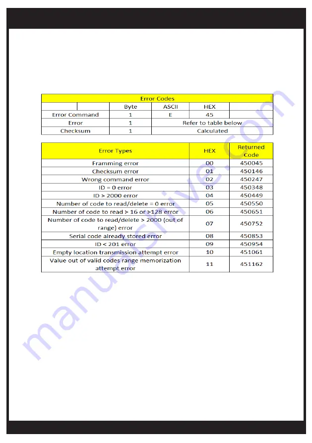
error definition table is shown below 

IF THE PAIRED REMOTE DOES NOT WORK WITH THE CONTROLLER, THE Bromic 
Smart-Heat

TM

 Link TROUBLESHOOTING STEPS IN THE TABLE WILL NOT WORK. In this 

case, troubleshoot the controller and remote devices using the instruction manual supplied 
with the controller

Summary of Contents for 2620279

Page 1: ...BROMIC SMART HEATTM LINK HOME AUTOMATION INSTALLATION INSTRUCTIONS IMPORTANT READ THIS MANUAL CAREFULLY SEE INSIDE COVER FOR IMPORTANT INFORMATION ABOUT THIS MANUAL KEEP INSTRUCTION WITH APPLIANCE FOR...

Page 2: ...Any other use not recommended by the manufacturer may cause radio interference fire electric shock or injury to persons This controller is intended for installation with a DC power supply Installatio...

Page 3: ...bromic com CONTENTS IMPORTANT NOTES WARNINGS 4 GETTING STARTED 5 TECHNICAL SPECIFICATIONS 6 INSTALLATION OPERATION 6 11 SUPPLEMENTARY INFORMATIONS 12 INSTALLATION INSTRUCTION 13 TROUBLESHOOTING 14...

Page 4: ...carpeting Do not cover with throw rugs runners or the like arrange cord away from traffic area and where it will not be tripped over This Installation and Operation manual should not be removed from t...

Page 5: ...cenced electrical contractor You will need the following supplied by others A compatible Home Automation system with RS232 communication port and RS232 programming interface Refer to your Home Automat...

Page 6: ...ion The Bromic controller remote has been pre programmed at the factory to operate with the supplied controller Check the operation of the remote and controller before beginning Refer to the instructi...

Page 7: ...romic Check the connections before plugging in the power supply and turning on If using a USB to RS232 convertor for the first time install the USB driver by following the instructions supplied with t...

Page 8: ...culation and error codes This is available from Bromic website www bromic com us outdoor heaters technical resources Instructions are based on Docklight but any other product with RS232 debugging read...

Page 9: ...Structure and Additional Codes for details on using ID locations 2 through 50 Using the Docklight command interface below program in the following transmit codes Green Column Follow the steps shown be...

Page 10: ...the Controller by checking the operation with the remote Open the remote cover by inserting flat screwdriver into bottom recess left and right side tabs Turn the screwdriver to release cover and acce...

Page 11: ...at the back section of this manual for troubleshooting 5 Repeat Steps 1 4 for all relevant button operations as shown in the photo below For the On Off Controller B2 B4 are the relevant commands and f...

Page 12: ...0002000157 540003000158 540004000159 2 2 75 2 CH 1 OFF 540002000258 540003000259 54000400025A 3 3 50 3 CH 2 ON 540002000359 54000300035A 54000400035B 4 4 25 4 CH 2 OFF 54000200045A 54000300045B 540004...

Page 13: ...e the RS232 connection can be made to the Home Automation System Your Home Automation System Integrator is required to perform this operation and program the codes and button functions into the Home A...

Page 14: ...HeatTM Link is transmitting receiving commands and any error codes that are generated Refer to the Bromic Smart HeatTM Link protocol document for command debugging The error definition table is shown...

Page 15: ...m Debug the transmission and receive commands using a RS232 transmission debugger and check for error codes Check for correct use of command protocols and checksum calculation Docklight returns FF Dev...

Reviews: