background image


BC300EN Broilchef Natural Gas Grill 
Owner’s Manual 

5


Always confirm that the installation of this grill conforms with the requirements of all local codes or, in the absence of applicable 
local codes, with either the National Fuel Gas Code, ANSI Z223. NFPA 54 or CAN/CGA-B149.2. 

  WARNING: Electrical Equipment Instruction


1. 

To protect against electric shock, do not immerse cord or plugs in water or other liquid. 

2.  Unplug from the outlet when not in use and before cleaning. Allow to cool before putting on or taking off the parts. 

3.  Do not operate any outdoor cooking gas appliance with a damaged cord, plug, or after the appliance malfunctions or has       

been damaged in any manner. Contact the manufacturer for repair. 

4.  Do not let the cord hang over the edge of a table or touch hot surface. 

5.  Do not use an outdoor cooking gas appliance for purposes other than intended. 

6.  When connecting, plug the appliance into the outlet directly. 

7.  Use only a Ground Fault Interrupt (GFI) protected circuit with this outdoor cooking gas appliance. 

8.  Never remove the grounding plug or use with an adaptor of 2 prongs. 

9.  Use only extension cords with a 3 prongs grounding plug, rated for the power of the equipment, and approved for outdoor       

use with a W-A marking


DANGER – Gas Safety


Natural gas is flammable and hazardous if handled improperly. Become aware of its characteristics before using any natural gas 

product. 

• Natural gas characteristics: Flammable, explosive under pressure, lighter than air and settles in pools in high areas. 

• In its natural state, natural gas has no odor. For your safety, an odorant has been added. 

• This grill is shipped from the factory for natural gas use only. 

CAUTION:


10.It is essential to keep the grill’s valve compartment, burners and circulating air passages clean. 

ƒ


Inspect the grill before each use

Step 1. Inspect all hoses and connections and make certain they are secure. 

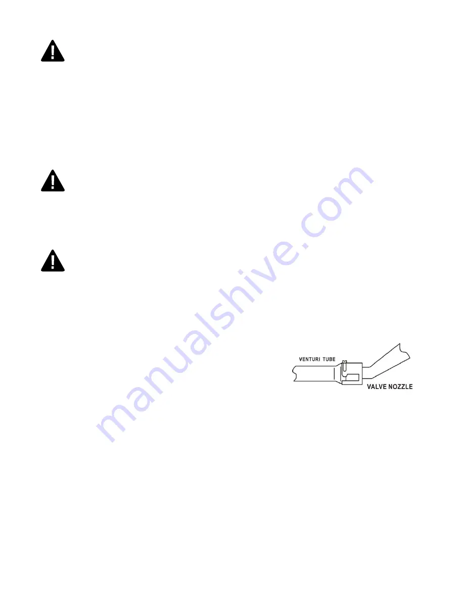
Step 2. Check and clean the burner venturi tubes for insects and insect nests by removing the burner and inserting a bottle 

brush cleaner into each tube to make sure the passage is clear. 

*** A clogged tube can lead to a fire beneath the grill. *** 

Step 3. Ensure that the valve nozzle is pointing straight and completely inserted into the venturi tube. 


General Information


1. 

A natural gas hose is required for operation.


2. 

This gas grill is NOT intended for commercial use.


Summary of Contents for Broil Chef BC300EN

Page 1: ...e installation operation and maintenance instructions thoroughly before installing or servicing this equipment DANGER Failure to follow these instructions could result in fire or explosion that could cause property damage personal injury or death MODEL BC300EN Broil Chef Natural Gas Barbecue SAVE THESE INSTRUCTIONS FOR FUTURE REFERENCE IF YOU ARE ASSEMBLING THIS UNIT FOR SOMEONE ELSE GIVE THIS MAN...

Page 2: ...es after use Step 2 Wait until the grill is completely cooled before closing lid Step 3 Clean up grease build up to avoid grease fire and cover your grill to prevent rust Always read and understand the WARNINGS and INSTRUCTIONS that are contained in this manual before attempting to use this gas barbecue grill to prevent possible bodily injury or property damage NOTE This grill must be used with na...

Page 3: ...nd assembly instructions suggestions for grilling and helpful hints as well as guidelines for the safe operation proper care and use of your grill Our expert staff strives to provide you with an easy to assemble product Should you have any questions or problems with this product please call our customer service department at 1 877 630 5396 10 00 am 19 00 pm EST Monday through Friday NOTE The use a...

Page 4: ... parts of the grill until they have completely cooled for at least 45 minutes or unless you are wearing protective gear such as pot holders protective gloves or mittens 2 Do not alter the grill in any manner 3 Clean and inspect the hose before each use If there is evidence of abrasion wear cuts or leaks the hose must be replaced prior to operation The replacement hose assembly should be in accorda...

Page 5: ...h an adaptor of 2 prongs 9 Use only extension cords with a 3 prongs grounding plug rated for the power of the equipment and approved for outdoor use with a W A marking DANGER Gas Safety Natural gas is flammable and hazardous if handled improperly Become aware of its characteristics before using any natural gas product Natural gas characteristics Flammable explosive under pressure lighter than air ...

Page 6: ...anel 1pc J Front beam 1pc K Door 1pc L Grease cup holder 1pc M Grease pan 1pc N Grease cup 1pc O Grill body 1pc P Left side table 1pc Q Left table front support 1pc R Left table back support 1pc S Side burner 1pc T Side burner grate 1pc U Grease cup 1pc V Right side table 1pc W Ice tank 1pc X Chopping board 1pc Y Cooking grate 3pcs Z Heating plate 7pcs AA Warming rack 1pc BB Handle 1pc CC Handle s...

Page 7: ...BC300EN Broilchef Natural Gas Grill Owner s Manual 7 Exploded View ...

Page 8: ...s included for your convenience Part Description Quantity Picture AA M6 x 30 Bolt 4 PCS BB M6 x 15 Bolt 40 PCS CC M4 x 10 Bolt 6 PCS DD M6 Flat Washer 44 PCS EE M6 Spring Washer 33 PCS FF M4 Flat Washer 6 PCS GG M10 Lock Nut 2 PCS HH Spacer 2 PCS II Screwdriver 1 PC JJ Wrench 2 PCS KK Battery 1 PC LL M6 x 15 Bolt 2 PCS MM M4 nut 2 PCS NN M4 spring washer 2 PCS ...

Page 9: ...d Put one spacer HH on each end of the axle e Put one wheel D on each end of the axle NOTE the protruding side of each wheel must face the bottom panel f Screwing one lock nut GG on end of the axle using the wrench provided g Cover the wheel cap E on the wheel h Repeat the procedure with the front wheel Step 2 Magnet door latch assembly a Align the two holes on the magnet door latch F with the two...

Page 10: ...es on right side of front beam J with the holes on the right panel H b Insert one bolt BB one spring washer EE and one flat washer DD into each pre drilled holes Tighten bolts by hand c Repeat the procedure on left side of front beam with the left panel d Go back and tighten all bolts using screwdriver provided Step 6 Door handle assembly a Align the holes on one of handle seat FF with the holes o...

Page 11: ... provided d Place grease cup N on grease cup support Step 9 Assemble the grill body to the cart a Put the grill body O on the top of cart assembly b Align the two holes on the top of cart left side panel with the two holes on the left side of body assembly c Insert one bolt AA one spring washer EE and one flat washer DD into each pre drilled hole Tighten bolts by hand until secure d Repeat the pro...

Page 12: ...pport Q and back support R with the holes on the bottom side of left table P b Insert one bolt BB one spring washer EE and one flat washer DD into each pre drilled holes Tighten bolts by hand c Go back and tighten all bolts using the screwdriver and wrench provided Step 12 Left side table assembly a Align the holes on left side table P with the holes on the left side of firebox b Insert one bolt B...

Page 13: ... into the pre drilled hole e Go back and tighten all bolts using the screwdriver and wrench provided Insert the ignition cable of side burner into electrode Step 14 Side burner ignition cable connection a Insert the ignition cable of the side burner into the electrode Step 15 Wind shield assembly a Loosen the pre installed bolts on on side table front support Q and back support R and allow 1 4 bol...

Page 14: ...y a Open the side table cover align the holes on right side table V with the holes on the right side wall of firebox b Insert one bolt BB one spring washer EE and one flat washer DD into each pre drilled holes Tighten bolts by hand c Align the holes on front of right side table with the holes on the right side of control panel d Insert one bolt LL into pre drilled hole Tighten bolts by hand e Go b...

Page 15: ...ice tank Step 20 Heating plates Cooking grates and warming rack installation a Put seven pieces heating plate Z on the plate support upon tube burners b Place three cooking grate Y upon the heating plates c Install warming rack AA by put the four legs on the side walls of firebox Step 21 Grease pan insertion a Insert the grease pan M into the guide underneath the firebox ...

Page 16: ...nsert the shaft BBB into the hole on the two forks FFF tighten the bolt on forks by hand until it is secured b Insert the balance block CCC and roller EEE into shaft in sequence as shown a Loosen the pre attached nuts and bolts on the motor support AAA b Align the hole one the motor support AAA w the hole on the left side wall of firebox c Insert one bolt one flat washer and one nut into each pre ...

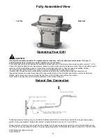
Page 17: ...utdoors after the gas line exits outside wall and before quick disconnect or before gas supply line enters ground Pipe sealing compound or pipe thread tape of the type resistant to the action of natural gas must be used on all male pipe threads Apply compound or tape to at least the first three to four threads when making connections Never store or use gasoline or other volatile substance in the v...

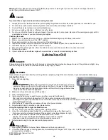
Page 18: ...which could cause serious bodily injury or death WARNING Never stand with your head directly over the grill when preparing to light the main burners to prevent possible bodily injury Lighting Main Burner 1 Open lid during lighting WARNING Attempting to light the burner with the lid closed may cause an explosion Make sure there are no obstructions of airflow to the gas unit Spiders and insects can ...

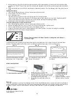
Page 19: ...te it counterclockwise to the HIGH position The burner should light immediately 5 Adjust valve knob to the desired cooking temperature Observe flame height when lit Flame should be a blue yellow color between 1 to 2 inches high Confirm that the burner is properly lit and that the flame pattern is as desired see fig A B and C below for the proper flame patterns If the flame pattern is other than no...

Page 20: ...rner is lit turn on the other control knob s to the HIGH position If you have more than two burners turn them on only ONE AT A TIME 13 When all front burners are lit close the grill lid 14 Wait for 10 15 minutes the temperature should reach 400 450 F Care and Maintenance IMPORTANT Always allow to completely cool off before covering your grill to prevent corrosion from condensation CAUTION All clea...

Page 21: ... tank is functioning refer to Excessive flow safety valve reset procedure on page 20 Turn the coupling nut about one half to three quarters additional turn until solid stop Tighten by hand ONLY do not use tools Clear burner tubes Check for bent or kinked hose Reengage burner and valve Clean venture or burner ports Burner will not light using a match No gas flow Coupling nut and regulator not fully...

Page 22: ...has expired customers will also be subject to parts fees Some provinces do not allow the limitation or exclusion of incidental or consequential damages so the above limitations or exclusions may not apply to you This warranty gives you specific legal rights and you may also have other rights that vary from province to province If you have any questions related to the product or warranty please cal...

Page 23: ...BC300EN Broilchef Natural Gas Grill Owner s Manual 23 Guang Dong China Printed in China ...

Reviews: