3-5
GAS PIPING
•
The unit is equipped with a 1/2” pipe for
gas connection. Shipped with each unit,
for 3/4” gas connection, is one each of
the following:
P/N 00743 - Bushing Hex Reducer
3/4 to 1/2
P/N 01319 - Coupling 3/4 Pipe
•
3/4 NPT minimum supply piping recom-
mended.
•
Use only black steel pipe and malleable
fittings for gas connections.
•
Pressure loss in the piping must not
exceed 0.3” W.C.
•
Be sure gas supply piping is of the
proper size for the BTU input. Take into
consideration all other gas appliances
which must operate from the same gas
supply. Be sure piping will not interfere
with drain pails or valves.
•
A compound resistant to the action of
liquified petroleum gas should be used
on the threads of gas supply piping
joints. Check all connections and pipes
with a soap and water solution. Bubbles
indicate a gas leak. DO NOT use an
open flame to check for gas leaks.
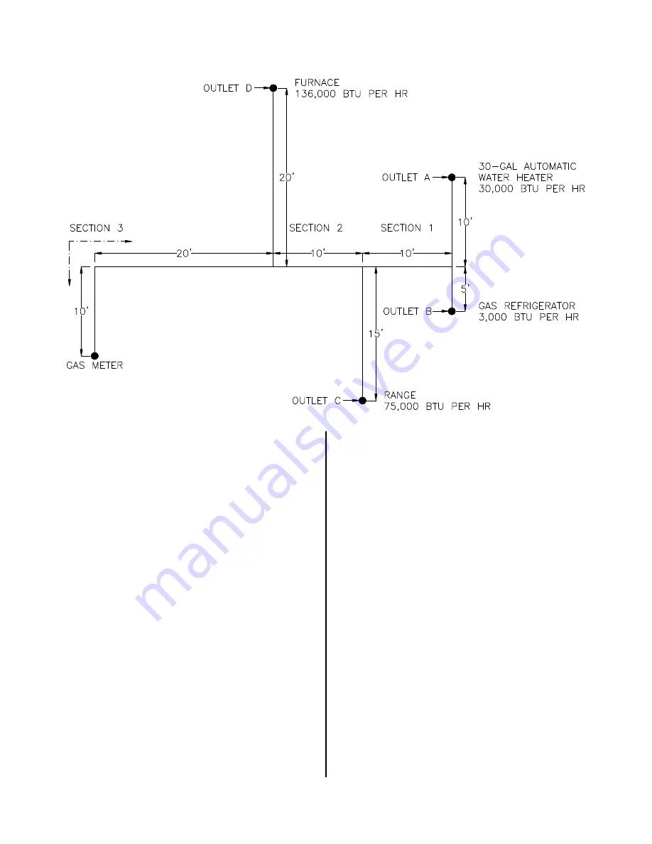
Determine the required pipe size of each
section and outlet of the piping system
shown in Solution, with a designated pres-
sure drop of 0.30 inch water column. Gas to
be used has 0.60 specific gravity and a
heating value of 1,000 BTU per cubic foot.
Example of Piping System Design:
broaster.com
Manual #17278 9/13 Rev 10/15
Summary of Contents for 2400 Series
Page 2: ......
Page 10: ...1 4 Hood Dimension In Millimeters broaster com Manual 17278 9 13 Rev 2 14 ...
Page 12: ......
Page 20: ...3 8 MODEL 2400GHCE UK broaster com Manual 17278 9 13 Rev 6 16 ...
Page 23: ...4 3 2400E 208 or 240VAC broaster com Manual 17278 9 13 Rev 9 16 ...
Page 24: ...4 4 EXPORT 2400E ST 220 380VAC to 240 415VAC broaster com Manual 17278 9 13 Rev 9 16 ...
Page 25: ...4 5 EU 2400ECE ST 230 400V broaster com Manual 17278 9 13 Rev 10 15 ...
Page 26: ......
Page 30: ......
Page 31: ......
Page 32: ...Broaster Company 2855 Cranston Road Beloit WI 53511 3991 608 365 0193 broaster com ...


