G720-Install-IG101 Installation Guide
Brocade
®
G720 Switch Hardware Installation Guide
The new power supply and fan assembly must have the same part number and airflow label (or lack thereof) as the power
supply and fan assembly already installed.
1. To leave the device in service while installing a power supply and fan assembly, verify that the other power supply and
fan assembly (the one already installed) has been powered on for at least four seconds and has a steady green LED.
2. Using a Phillips screwdriver, unscrew the captive screw of the filler panel that is located in the empty power supply and
fan assembly slot.
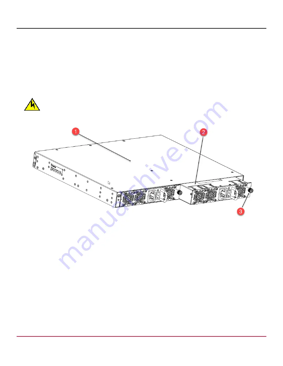
3. Orient the new power supply and fan assembly with the captive screw on the right, as shown in the following figure.
Do not force the installation. If the power supply and fan assembly does not slide in easily, ensure that it is correctly
oriented before continuing.
CAUTION
Carefully follow the mechanical guides on each side of the power supply slot and make sure the power
supply is properly inserted in the guides. Never insert the power supply upside down.
Figure 30: Inserting an AC Power Supply and Fan Assembly
1. Device
2. AC Power Supply and Fan Assembly
3. Captive Screw
4. Gently push the power supply and fan assembly into the chassis until it is firmly seated.
5. Using the Phillips screwdriver, secure the power supply and fan assembly to the chassis by tightening the captive
screw.
6. Plug the power cord into the power supply and fan assembly and power on the unit by flipping the PSU power switch
to the on position (the “I” symbol).
7. Verify that the LED on the new power supply and fan assembly displays a steady green light while the device is
operating.
If the LED is not a steady green, ensure that the power supply is securely installed and seated properly.
8. Optional: Enter
psshow
to display the PSU status.
The power supply and fan assembly status can also be viewed using Web Tools.
G720-Install-IG101
68
Broadcom
Summary of Contents for Brocade G720
Page 86: ......


