background image

53-1005235-09 Installation Guide


Brocade

®

 G630 Switch Hardware Installation Guide

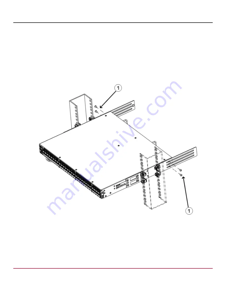
Attaching the Rear Brackets to the Device

Complete the following steps to attach the rear brackets to the device:
1. Align the right rear bracket to the right rear of the device, and use four 8-32 x 5/16-in. panhead screws to attach the

bracket to the device, as shown in the following figure. Be sure to insert the screws through the upper and lower slots

in the bracket.

2. Align the left rear bracket to the left rear of the device, and use four 8-32 x 5/16-in. panhead screws to attach the

bracket to the device. Again, use the upper and lower slots in the bracket.

3. Tighten all 8-32 x 5/16-in. screws to a torque of 17 cm-kg (15 in.-lb).

Figure 24: Attaching the Rear Brackets to the Device

1. Screws, 8-32 x 5/16-in. Panhead Phillips


53-1005235-09

48

Summary of Contents for Brocade G630-1

Page 1: ...Brocade G630 Switch Hardware Installation Guide Installation Guide 9 April 2021 53 1005235 09 9 April 2021 ...

Page 2: ...s 15 General Precautions 15 ESD Precautions 16 Power Precautions 16 Lifting and Weight Related Precautions 17 Laser Precautions 17 Facility Requirements 17 Quick Installation Checklist 18 Shipping Carton Contents 20 Mounting the Device 22 Mounting Options 22 Precautions Specific to Mounting 22 Stand Alone Installation 23 Installing the Universal Four Post Rack Kit XBR R000296 23 Time and Items Req...

Page 3: ...id Mounting 43 Attaching the Front Brackets to the Device 45 Attaching the Front Brackets to the Rack 46 Attaching the Rear Brackets to the Rack 47 Attaching the Rear Brackets to the Device 48 Initial Setup and Verification 49 Items Required 49 Providing Power to the Device 49 Establishing a First Time Serial Connection 49 Configuring the IP Address 50 Using DHCP to Set the IP Address 50 Setting a...

Page 4: ...ply Assemblies 70 Power Supply Assembly Overview 70 Precautions Specific to the Power Supply Assemblies 71 Identifying the Airflow Direction 71 Power Supply Assembly Fault Indicators 72 Power Supply Assembly Task Guide 72 Time and Items Required 73 Recording Critical Information about the Power Supply Assembly 73 Removing a Power Supply Assembly 74 Inserting a New Power Supply Assembly 74 Verifyin...

Page 5: ...ecifications 82 Regulatory Statements 87 BSMI Statement Taiwan 87 Canadian Requirements 87 CE Statement 87 China CCC Statement 88 China ROHS 89 FCC Warning U S Only 89 Germany Statement 89 KCC Statement Republic of Korea 89 Taiwan ROHS Certification 90 VCCI Statement 90 Regulatory Compliance 91 Cautions and Danger Notices 92 Cautions 92 Danger Notices 95 Revision History 98 53 1005235 09 5 ...

Page 6: ...m does not assume any liability arising out of the application or use of this information nor the application or use of any product or circuit described herein neither does it convey any license under its patent rights nor the rights of others The product described by this document may contain open source software covered by the GNU General Public License or other open source license agreements To...

Page 7: ...d OS Currently Supported OS 173 G630 1 Fabric OS 8 2 0 Fabric OS 8 x Fabric OS 9 x 184 G630 2 Fabric OS 9 0 0 Fabric OS 9 x NOTE To obtain the switch type use the switchShow command NOTE Fabric OS 8 x refers to any supported release within the 8 x generation of Fabric OS Fabric OS 9 x refers to any supported release within the 9 x generation of Fabric OS Table 2 Power Supply and Fan Assemblies Par...

Page 8: ...t issues the preferred method is to log in to myBroadcom at https www broadcom com mybroadcom You must initially register to gain access to the Customer Support Portal Once there select Customer Support Portal Support Portal You will now be able to navigate to the following sites Knowledge Search Clicking the top right magnifying glass brings up a search bar Case Management The legacy MyBrocade ca...

Page 9: ...to ensure the accuracy and completeness of this document However if you find an error or an omission or if you think that a topic needs further development we want to hear from you Send your feedback to documentation pdl broadcom com Provide the publication title publication number topic heading page number and as much detail as possible 53 1005235 09 9 ...

Page 10: ...upport a speed of 10G NOTE The port speed is determined by the maximum negotiated speed between the installed transceiver and the optical transceiver at the other end of the link Universal ports that self configure as E_Ports F_Ports D_Ports or EX_Ports and can be activated on a per port basis with the optional Integrated Routing IR license The Diagnostic D_Port mode provides diagnostics troublesh...

Page 11: ...ging functionality by facilitating easier firmware upgrades and downloads of the system log files One external USB Type A connector Two hot swappable redundant power supply FRUs Three hot swappable redundant fan assembly FRUs 128 bicolor green amber LEDs to indicate the status for each port One green LED to indicate valid system power One bicolor green amber LED to indicate the system status Two E...

Page 12: ...SFP Port 4 FC Ports 112 115 13 48 SFP 32G FC Ports 14 10 100 1000Mb s RJ 45 Ethernet Management Port 15 UART RJ 45 Serial Console Port Table 5 SFP Port Numbering 0 1 2 3 8 9 10 11 16 17 18 19 24 25 26 27 32 33 34 35 40 41 42 43 4 5 6 7 12 13 14 15 20 21 22 23 28 29 30 31 36 37 38 39 44 45 46 47 48 49 50 51 56 57 58 59 64 65 66 67 72 73 74 75 80 81 82 83 88 89 90 91 52 53 54 55 60 61 62 63 68 69 70...

Page 13: ...ply Receptacle 2 7 Power Supply Receptacle 1 8 Power Supply Unit 1 9 Fan Assembly Unit 1 Status LED 10 Fan Assembly Unit 2 Status LED 11 Fan Assembly Unit 3 Status LED Device Management Options You can use the management functions built into the device to monitor the fabric topology port status physical status and other information This functionality helps you analyze switch performance and to acc...

Page 14: ...lete the basic configuration for a single switch setup Ethernet or serial connection EZSwitchSetup Software Installation Guide Brocade EZSwitchSetup Administration Guide Brocade Web Tools Ethernet or serial connection Brocade Fabric OS Web Tools Administration Guide Standard SNMP applications Ethernet or serial connection Brocade Fabric OS MIB Reference Manual Management Server Ethernet or serial ...

Page 15: ...ible for compliance could void the user s authority to operate the equipment CAUTION Disassembling any part of the power supply and fan assembly voids the warranty and regulatory certifications There are no user serviceable parts inside the power supply and fan assembly CAUTION Make sure the airflow around the front and back of the device is not restricted CAUTION Ensure that the airflow direction...

Page 16: ...s in your country The mark is your assurance that the power cord can be used safely with the device DANGER This device might have more than one power cord To reduce the risk of electric shock disconnect all power cords before servicing DANGER Remove both power cords before servicing DANGER Disconnect the power cord from all power sources to completely remove power from the device DANGER To avoid h...

Page 17: ... the port cover tabs to lift the module They are not designed to support the weight of the module which can fall and be damaged CAUTION To prevent damage to the chassis and components never attempt to lift the chassis using the fan or power supply handles These handles were not designed to support the weight of the chassis Laser Precautions DANGER All fiber optic interfaces use Class 1 lasers DANG...

Page 18: ...e circuit is protected by a circuit breaker and grounded in accordance with local electrical codes See the Technical Specifications section for power supply specifications Thermal Ambient air temperature not exceeding 40 C 104 F while the switch is operating Rack when rack mounted All equipment in the rack grounded through a reliable branch circuit connection The additional weight of the switch mu...

Page 19: ...nt kit See Mounting Options Review and verify the installation requirements Verify that the following requirements are met See Facility Requirements Power requirements Environmental requirements Clearance for a stand alone or rack installation Gather network configuration parameters IP address Subnet mask Default gateway Domain ID Time zone Installation and Initial Configuration The initial setup ...

Page 20: ...net connection By establishing an Ethernet connection you can complete the device configuration using a serial session Telnet or management application such as Brocade Network Advisor See Establishing an Ethernet Connection Optional Configure the DNS service Use the dnsconfig command to create DNS server entries See the Brocade Fabric OS Administration Guide for details on using this command Optio...

Page 21: ...items A serial cable Two 6 ft power cords Power cord retainer clips Rubber feet China RoHS Hazardous Toxic Substance statement Brocade SANnav web pointer card EZSwitch web pointer card Brocade documentation web pointer card Inner foam NOTE Transceivers may be shipped in the accessory tray instead of installed in switch ports 53 1005235 09 21 ...

Page 22: ...ications Telco rack NOTE Review the following precautions before mounting the device Precautions Specific to Mounting The following precautions specifically apply to mounting the device DANGER Use safe lifting practices when moving the product DANGER Mount the devices you install in a rack as low as possible Place the heaviest device at the bottom and progressively place lighter devices above CAUT...

Page 23: ...with the front posts With the nonport side flush with the rear posts in a recessed position A recessed position allows a more gradual bend in the fiber optic cables that are connected to the switch and less interference in the aisle at the front of the rack Table 11 Space Requirements Chassis with Port Side Side Vents Notes Chassis Depth Minimum Rack Depth Maximum Rack Depth No Applicable to port ...

Page 24: ... Kit No 2 Phillips torque screwdriver 1 4 in slotted blade torque screwdriver Parts List The following parts are provided with the 1U 1 5U and 2U Universal Four Post Rack Kit XBR R000296 Figure 4 Universal Four Post Rack Kit Parts 1 Front Brackets 2 2 Extension Brackets Medium 2 3 Rear Brackets Short 2 4 Rear Brackets Long 2 5 Bracket Extensions Long 2 53 1005235 09 24 ...

Page 25: ...AUTION Use the screws specified in the procedure Using longer screws can damage the device Flush Front Mounting CAUTION The device must be turned off and disconnected from the fabric during this procedure NOTE The illustrations in the rack installation procedures are for reference only and may not show the device that you are installing Complete the following tasks to install the device in a four ...

Page 26: ...llowing figure 2 Insert four 8 32 x 5 16 in flathead screws through the vertically aligned holes in the bracket and then into the holes on the side of the device Use the upper and lower screw holes leaving the center holes empty 3 Repeat Step 1 and Step 2 to attach the left front bracket to the left side of the device 4 Tighten all 8 32 x 5 16 in screws to a torque of 17 cm kg 15 in lb Figure 5 At...

Page 27: ... the side of the device as shown in the following figure 3 Insert four 8 32 x 5 16 in flathead screws through the vertically aligned holes in the bracket extension and then into the holes on the side of the device Use the upper and lower screw holes leaving the center holes empty 4 Repeat Steps 2 and 3 to attach the left extension bracket to the left side of the device 5 Tighten all 8 32 x 5 16 in...

Page 28: ...ll 10 32 x 5 8 in screws to a torque of 29 cm kg 25 in lb Figure 7 Positioning the Device in the Rack 1 Screws 10 32 x 5 8 in Panhead Phillips 2 Retainer Nuts 10 32 Attaching the Rear Brackets to the Extensions Complete the following steps to attach the rear brackets to the extensions You can use short or long rear brackets for this task depending on the depth of your rack 1 Select the proper leng...

Page 29: ... 3 to attach the left rear bracket to the left extension bracket 5 Adjust the brackets to the rack depth and tighten all 6 32 x 1 4 in screws to a torque of 10 cm kg 9 in lb Figure 8 Attaching the Rear Brackets to the Extensions 1 Rear Brackets 2 Screws 6 32 x 1 4 in Panhead Phillips 53 1005235 09 29 ...

Page 30: ... Attach the left rear bracket to the left rear rack post using two 10 32 x 5 8 in panhead screws and two retainer nuts Use the upper and lower holes in the bracket 3 Tighten all 10 32 x 5 8 in screws to a torque of 29 cm kg 25 in lb Figure 9 Attaching the Rear Brackets to the Rack Posts 1 Screws 10 32 x 5 8 in Panhead Phillips 2 Retainer Nuts 10 32 Flush Rear Recessed Mounting Flush rear recessed ...

Page 31: ...nstall the device in a four post rack 1 Attaching the Front Brackets to the Rear of the Device 2 Attaching the Extensions to the Front of the Device 3 Installing the Device in the Rack 4 Attaching the Rear Brackets to the Extensions at the Front of the Device 5 Attaching the Rear Brackets to the Front Rack Posts Attaching the Front Brackets to the Rear of the Device NOTE In this installation the b...

Page 32: ...32 x 5 16 in flathead screws through the vertically aligned holes in the bracket and then into the holes on the side of the device Use the upper and lower screw holes leaving the center holes empty 3 Repeat Steps 1 and 2 to attach the left front bracket to the left side of the device 4 Tighten all 8 32 x 5 16 in screws to a torque of 17 cm kg 15 in lb Figure 10 Attaching the Front Brackets to the ...

Page 33: ...t extension bracket along the side of the device as shown in the following figure 3 Insert four 8 32 x 5 16 in flathead screws through the vertically aligned holes in the extension brackets and then into the holes on the side of the device Use the upper and lower screw holes leaving the center holes empty 4 Repeat Steps 2 and 3 to attach the left front extension bracket to the left side of the dev...

Page 34: ...er and lower holes in the bracket 3 Tighten all 10 32 x 5 8 in screws to a torque of 29 cm kg 25 in lb Figure 12 Positioning the Device in the Rack 1 Screws 10 32 x 5 8 in Panhead Phillips 2 Retainer Nuts 10 32 Attaching the Rear Brackets to the Extensions at the Front of the Device Complete the following steps to attach the rear brackets to the extensions Rack depth determines the use of short or...

Page 35: ... Repeat Steps 2 and 3 to attach the left rear bracket to the left extension 5 Adjust the brackets to the rack depth and tighten all 6 32 x 1 4 in screws to a torque of 10 cm kg 9 in lb Figure 13 Attaching the Rear Brackets to the Extensions at the Front of the Device 1 Rear Brackets Short 2 Screws 6 32 x 1 4 in Panhead Phillips 53 1005235 09 35 ...

Page 36: ...tallation Guide Brocade G630 Switch Hardware Installation Guide Figure 14 Attaching the Short or Long Rear Brackets to the Extensions 1 Rear Bracket Short or Long 2 Screws 6 32 x 1 4 in Panhead Phillips 53 1005235 09 36 ...

Page 37: ...the bracket 2 Attach the left rear bracket to the left front rack post using two 10 32 x 5 8 in screws and two retainer nuts Use the upper and lower holes in the bracket 3 Tighten all 10 32 x 5 8 in screws to a torque of 29 cm kg 25 in lb Figure 15 Attaching the Rear Brackets to the Front Rack Posts 1 Screws 10 32 x 5 8 in Panhead Phillips 2 Retainer Nuts 10 32 Installing the Universal Two Post Ra...

Page 38: ...ices that are illustrated in these procedures are for reference only and may not depict the device that you are installing into the rack Time and Items Required Allow 15 to 30 minutes to complete the installation The following items are required to install the device using the Universal Two Post Rack Kit No 2 Phillips torque screwdriver 1 4 in slotted blade torque screwdriver Parts List The follow...

Page 39: ... turned off and disconnected from the fabric during this procedure The figures in this document show a 1U device but the instructions are the same for a 2U device The figures for this procedure show a two post rack with narrow posts 3 in to 5 in as an example The figures in the rack installation procedures are for reference only and may not show the actual device CAUTION Use the screws specified i...

Page 40: ... 2 Insert four 8 32 x 5 16 in flathead screws through the vertically aligned holes in the bracket and then into the holes on the side of the device Use the upper and lower screw holes leaving the center holes empty 3 Repeat Steps 1 and 2 to attach the left front bracket to the left side of the device 4 Tighten all the 8 32 x 5 16 in screws to a torque of 17 cm kg 15 in lb Figure 17 Attaching the F...

Page 41: ...e rack 2 Attach the right front bracket to the right rack upright using two 10 32 x 5 8 in panhead screws and two retainer nuts Use the upper and lower holes in the bracket 3 Attach the left front bracket to the left rack upright using two 10 32 x 5 8 in panhead screws and two retainer nuts Use the upper and lower holes in the bracket 4 Tighten all the 10 32 x 5 8 in screws to a torque of 29 cm kg...

Page 42: ...brackets marked 5 6 INCH 2 Position the right rear bracket in the right rear of the device as shown in the following figure 3 Attach the bracket to the right rack upright using two 10 32 x 5 8 in panhead screws and two retainer nuts Use the upper and lower holes in the bracket 4 Repeat Steps 2 and 3 to attach the left rear bracket to the left rack upright 5 Tighten all the 10 32 x 5 8 in screws to...

Page 43: ...in the following figure Be sure to insert the screws through the upper and lower slots in the bracket 2 Align the left rear bracket to the left rear of the device and use four 8 32 x 5 16 in panhead screws to attach the bracket to the device Again use the upper and lower slots in the bracket 3 Tighten all the 8 32 x 5 16 in screws to a torque of 17 cm kg 15 in lb Figure 20 Attaching the Rear Brack...

Page 44: ...e but the instructions are the same for a 2U device The illustrations in the rack installation procedures are for reference only and may not show the actual device Complete the following tasks to install the device in the rack 1 Attaching the Front Brackets to the Device 2 Attaching the Front Brackets to the Rack 3 Attaching the Rear Brackets to the Rack 4 Attaching the Rear Brackets to the Device...

Page 45: ...re 2 Insert four 8 32 x 5 16 in flathead screws through the vertically aligned holes in the bracket and then into the holes on the side of the device Use the upper and lower screw holes leaving the center holes empty 3 Repeat Steps 1 and 2 to attach the left front bracket to the left side of the device 4 Tighten all 8 32 x 5 16 in screws to a torque of 17 cm kg 15 in lb Figure 21 Attaching the Fro...

Page 46: ... secured to the rack 2 Attach the right front bracket to the right rack upright using two 10 32 x 5 8 in screws and two retainer nuts Use the upper and lower holes in the bracket 3 Attach the left front bracket to the left rack upright using two 10 32 x 5 8 in screws and two retainer nuts Use the upper and lower holes in the bracket 4 Tighten all 10 32 x 5 8 in screws to a torque of 29 cm kg 25 in...

Page 47: ... in the right rear of the device as shown in the following figure Whether you are using the 3 5 INCH or the 5 6 INCH bracket the rear end of the bracket will be flush with the back of the device 3 Attach the brackets to the right rack upright using two 10 32 x 5 8 in panhead screws and two retainer nuts 4 Repeat Step 2 and Step 3 to attach the left rear bracket to the left rack upright 5 Tighten a...

Page 48: ...ch the bracket to the device as shown in the following figure Be sure to insert the screws through the upper and lower slots in the bracket 2 Align the left rear bracket to the left rear of the device and use four 8 32 x 5 16 in panhead screws to attach the bracket to the device Again use the upper and lower slots in the bracket 3 Tighten all 8 32 x 5 16 in screws to a torque of 17 cm kg 15 in lb ...

Page 49: ...ed and can be purchased from other suppliers Providing Power to the Device Perform the following steps to provide power to the device 1 Connect the power cords to both power supplies and then to power sources on separate circuits to protect against power failure Ensure that the power cords have a minimum service loop of 6 in available and that they are routed to avoid stress 2 Power on the power s...

Page 50: ...the device as admin using the default password password You are prompted to change the default user name and password at initial logon Make sure to write down the new credentials and keep this information in a secure location Fabric OS swDir swDir login admin Password Please change your passwords now Use Control C to exit or press Enter key to proceed swDir admin 6 Modify the credentials To cancel...

Page 51: ...peration does not depend on the date and time a device with an incorrect date or time value still functions properly You can synchronize the local time of the principal or primary fabric configuration server FCS device to that of an external Network Time Protocol NTP server Perform the following steps to set the date and time 1 Log on to the device as admin 2 Enter the date new date command at the...

Page 52: ...Local Time tsTimeZone Parameter Difference from UTC Atlantic Standard 4 0 Atlantic Daylight 3 0 Eastern Standard 5 0 Eastern Daylight 4 0 Central Standard 6 0 Central Daylight 5 0 Mountain Standard 7 0 Mountain Daylight 6 0 Pacific Standard 8 0 Pacific Daylight 7 0 Alaskan Standard 9 0 Alaskan Daylight 8 0 Hawaiian Standard 10 0 3 Reboot the device Synchronizing the Local Time with an External Sou...

Page 53: ...k that connects the workstation NOTE At this point the device can be accessed remotely using either the command line or Brocade Web Tools Ensure that the device is not being modified from any other connections during the remaining tasks in this chapter The Ethernet management port also supports Auto MDI MDIX Setting the Domain ID Perform the following steps to set the switch domain ID 1 Log on to ...

Page 54: ...w Displays switch status and information tempShow Displays temperature status and information The switchShow command provides the following information about the device and its ports E_G630_2 admin switchshow switchName E_G630_2_209 switchType 184 1 switchState Online switchMode Native switchRole Subordinate switchDomain 209 switchId fffcd1 switchWwn 10 00 d8 1f cc 05 3f bb zoning ON fos6k switchB...

Page 55: ... Port116 114 114 d17200 id N32 Online FC E Port Trunk port master is Port116 115 115 d17300 id N32 Online FC E Port Trunk port master is Port116 116 116 d17400 id N32 Online FC E Port 10 00 00 27 f8 f2 76 f9 Core X7 8_Upgraded_130057_LS1 downstream Trunk master 117 117 d17500 id N32 Online FC E Port Trunk port master is Port116 118 118 d17600 id N32 Online FC E Port Trunk port master is Port116 11...

Page 56: ...downloading to a replacement device if necessary NOTE By default the Virtual Fabrics VF is enabled You must use the configupload vf command to upload configuration for the virtual fabric all logical switches configured on the device For detailed information on the configupload download refer to the Brocade Fabric OS Administration Guide Powering Down the Device Complete the following steps to powe...

Page 57: ...imum bend radius for a 50 micron cable is 2 in under a full tensile load and 1 2 in with no tensile load Cables can be organized and managed in various ways for example using cable channels on the sides of the rack or patch panels to minimize cable management Follow these recommendations NOTE You should not use tie wraps with optical cables because they are easily overtightened and can damage the ...

Page 58: ...l it is firmly seated and the latching mechanism clicks NOTE Each SFP transceiver has a 10 pad gold plated PCB edge connector on the bottom The correct position to insert an SFP transceiver into the upper row of ports is with the gold edge down The correct position to insert an SFP transceiver into the lower row of ports is with the gold edge up Figure 25 Installing an SFP Transceiver into an Uppe...

Page 59: ...iver into the port Transceivers are keyed so that they can be inserted only with the correct orientation If a transceiver does not slide in easily ensure that it is correctly oriented NOTE Each SFP transceiver has a 10 pad gold plated PCB edge connector on the bottom The correct position to insert an SFP transceiver into the upper row of ports is with the gold edge down The correct position to ins...

Page 60: ... the QSFP transceivers since the QSFP might be hot 1 Use the pull tab on these transceivers to help push the transceiver into the port Transceivers are keyed so that they can be inserted only with the correct orientation If a transceiver does not slide in easily ensure that it is correctly oriented Push the correctly oriented transceiver into the port until it is firmly seated and the latching mec...

Page 61: ...emove and then install a new QSFP transceiver NOTE QSFP transceivers have pull tabs rather than bails Always use the pull tab to insert or remove the QSFP transceivers since the QSFP might be hot 1 Remove any cables that are inserted into the transceiver 2 Grasp the QSFP transceiver pull tab and gently pull out the tab straight NOTE Grasp the pull tab near the body of the transceiver to reduce the...

Page 62: ... the latching mechanism clicks NOTE Cables are keyed so that they can be inserted in only one way If a cable does not slide in easily ensure that it is correctly oriented Verifying the Operation of New Transceivers You can use the following commands to verify if the transceivers are working correctly errDump fabricShow sfpShow switchShow Refer to the Brocade Fabric OS Command Reference Manual for ...

Page 63: ...er Sometimes the LEDs may flash either of the colors during boot POST or other diagnostic tests This is normal it does not indicate a problem unless the LEDs do not indicate a healthy state after all boot processes and diagnostic tests are complete Figure 29 Brocade G630 Port Side LEDs 1 System Power LED 2 System Status LED 3 SFP Upper Port 1 4 SFP Upper Port 1 Status LED 5 SFP Lower Port 7 6 SFP ...

Page 64: ...n The system is on and power supplies are functioning properly No action is required System Status LED Use the following table to interpret the system status LED Table 14 System Status LED Patterns during Normal Operation LED Color Status of Hardware Recommended Action No light The system is off or there is no power Verify that the system is on and has completed booting Steady green The POST and i...

Page 65: ...ializing The connected device is configured in an offline state Verify that the power LED is on and check the SFP and cable Verify that the device is not currently being initialized Verify the status of the connected device Steady green The port is online connected to an external device but has no traffic No action is required Slow flashing green on for 1 second then off for 1 second The port is o...

Page 66: ...Verify that the correct device is attached to the switch Fast flashing green on for 1 4 second then off for 1 4 second Port is online and an internal loopback diagnostic test is running No action is required Flickering green Port is online and frames are flowing through the port No action is required Steady amber Port is receiving light or signal carrier but it is not online yet No action is requi...

Page 67: ...ED Description Action Required Off Off No AC power to all the power supplies No action is required Off Blinking amber Power supply continues to operate but is experiencing high temperature high power or a slow fan Check and replace the power supply unit before it fails completely Off Steady amber Power supply unit failed due to overvoltage overcurrent overtemperature or fan failure Check and repla...

Page 68: ... to persistently disable the POST The success or failure results of the diagnostic tests that run during the POST can be monitored through LED activity the error log or the command line interface During the POST the LEDs flash different colors The POST performs the following tasks Conducts preliminary POST diagnostics Initializes the operating system Initializes the hardware Runs diagnostic tests ...

Page 69: ...s test the internal connections and circuitry the fixed media and the transceivers and cables in use The tests are implemented by command either through a Telnet session or through a terminal setup for a serial connection to the device Some tests require that the ports be connected by external cables to allow diagnostics to verify the serializer or deserializer interface transceiver and cable Some...

Page 70: ... can continue to operate during the replacement The device supports the following types of power supplies AC power supply with nonport side air exhaust This unit moves the air from the port side to the nonport side of the device AC power supply with nonport side air intake This unit moves the air from the nonport side to the port side of the device Figure 31 AC Power Supply Assembly 1 Power Supply...

Page 71: ...an be used safely with the device CAUTION Disassembling any part of the power supply and fan assembly voids the warranty and regulatory certifications There are no user serviceable parts inside the power supply and fan assembly CAUTION Ensure that the airflow direction of the power supply unit matches that of the installed fan tray The power supplies and fan trays are clearly labeled with either a...

Page 72: ... supply OK and FAIL status LEDs See Power Supply OK and FAIL Status LEDs to interpret the meaning of LED operation In Web Tools click the Power Status icon Enter the psShow command at the prompt to display power supply assembly status as shown in the following example Device admin psshow Power Supply 1 is OK Power Supply 2 is OK Power Supply Assembly Task Guide You can perform an easy set of steps...

Page 73: ...ommand 2 Power down both power supply assemblies 3 Remove the power supply assemblies being replaced 4 Insert the new power supply assemblies 5 Power on the power supply assemblies 6 Verify the power supply assemblies OK and FAIL status LEDs Time and Items Required Installing or removing and replacing a power supply assembly should require less than 5 minutes to complete The following items are re...

Page 74: ...ower supply assembly from the chassis by pulling the handle out and away from the chassis Inserting a New Power Supply Assembly Perform the following steps to insert a new power supply assembly into the chassis The new power supply assembly must have the same part number and airflow label or lack thereof as the power supply assembly already installed 1 To leave the device in service while installi...

Page 75: ...wer is provided to the device immediately 4 Verify that the LED on the new power supply assembly displays a steady green light while the device is operating If the LED is not a steady green ensure that the power supply is securely installed and seated properly 5 Optional Enter psshow to display the PSU status The power supply assembly status can also be viewed using Web Tools Verifying the Operati...

Page 76: ... This unit moves the air from the port side to the nonport side of the device Fan assembly with nonport side air intake This unit moves the air from the nonport side to the port side of the device Figure 34 Fan Assembly 1 Captive Screw 2 Fan Assembly Unit Handle The device fans are fixed inside the fan assemblies to provide necessary airflow to cool the whole system Two fans are located in each un...

Page 77: ...r supply in a slot you must keep the slot filler panel in place If you run the chassis with an uncovered slot the system will overheat CAUTION To prevent damage to the chassis and components never attempt to lift the chassis using the fan or power supply handles These handles were not designed to support the weight of the chassis NOTE The equipment installation must meet NEC CEC code requirements ...

Page 78: ...your device is up and running with two fan assemblies and you want to install an extra fan assembly complete the following steps 1 Remove the existing filler panel 2 Insert the new fan assembly 3 Verify the fan assembly status LED Replacing a Fan Assembly Hot Swap If your device is up and running with three fan assemblies but one of them has failed complete the following steps 1 Remove the old or ...

Page 79: ...hassisshow fanshow historyshow psshow sensorshow tempshow Refer to the Brocade Fabric OS Command Reference Manual for output examples and descriptions Removing a Fan Assembly Perform the following steps to remove a faulty fan assembly 1 To leave the device in service while removing a fan assembly verify that the other power supplies and fan assemblies the ones not being replaced have been powered ...

Page 80: ...of as the fan assemblies already installed 1 To leave the device in service while installing a fan assembly verify that the other fan assemblies the ones already installed have been powered on for at least 4 seconds and have a steady green LED 2 Using a Phillips screwdriver unscrew the captive screw of the filler panel that is located in the empty fan assembly slot 3 Orient the new fan assembly wi...

Page 81: ... assembly displays a steady green light while the device is operating 7 Optional Enter fanshow to display the fan assembly status The fan assembly status can also be viewed using Web Tools Verifying the Operation of the Power Supply and Fan Assemblies You can use the following commands to verify that the power supply and fan assemblies are operational errDump fanShow psShow switchShow Refer to the...

Page 82: ...SFP ports are capable of auto negotiating to 4 8 16 or 32G speeds depending on the SFP model and the minimum supported speed of the optical transceiver at the other end of the link 10G performance is enabled by 10G SFP transceivers if the other end of the connection also has a speed of 10G 4G 8G and 16G performance is enabled by 16G SFP transceivers if the other end of the connection has a minimum...

Page 83: ...EDs One bicolor fan assembly status LED on each fan assembly on the nonport side of the switch Cables Adapters and Connectors The hardware that is required for the serial connection depends on the SKU number System Component Description Serial cable RJ 45 console cable RJ 45 to DB9 adapter RJ 45 to DB9 for the console cable RJ 45 connector RJ 45 connector for the serial port Weight and Physical Di...

Page 84: ...iciently cool down and may result in excessive inrush current XBR 1500WPSAC R 1500W 100 240 VAC nominal 90 264 VAC range 50 60 Hz nominal 47 63 Hz range 7A 12A Line fused 40A peak Do not repeat plug in and plug out operations within a short time or else the internal inrush current limiting device NTC may not sufficiently cool down and may result in excessive inrush current Data Port Specifications...

Page 85: ...8 ft OM3 125m 410 ft OM4 N A N A 62 5 15m 49 ft N A N A 16 9 N A 10 km 6 2 miles 25 km 15 5 miles 50 70m 230 ft OM3 100m 328 ft OM4 N A N A 62 5 N A N A N A 32 9 N A 10 km 6 2 miles 25 km 15 5 miles Serial Port Specifications RJ 45 Pinout NOTE These specifications are for the serial connectors on Brocade platforms only Pin Number Signal Description 1 Not supported N A 2 Not supported N A 3 TXD Tra...

Page 86: ...53 1005235 09 Installation Guide Brocade G630 Switch Hardware Installation Guide Parameter Value Stop bits 1 53 1005235 09 86 ...

Page 87: ...érique de la classe A est conforme à la norme NMB 003 du Canada CE Statement ATTENTION This is Class A product In a domestic environment this product may cause radio interference in which case the user may be required to take adequate measures The standards compliance label on this device contains the CE mark which indicates that this system conforms to the provisions of the following European Cou...

Page 88: ...53 1005235 09 Installation Guide Brocade G630 Switch Hardware Installation Guide China CCC Statement 53 1005235 09 88 ...

Page 89: ...mful interference to radio communications Operation of this equipment in a residential area is likely to cause harmful interference in which case the user will be required to correct the interference at the user s own expense Germany Statement Machine noise information regulation 3 GPSGV the highest sound pressure level value is 70 0 dB A in accordance with EN ISO 7779 Maschinenlärminformations Ve...

Page 90: ...53 1005235 09 Installation Guide Brocade G630 Switch Hardware Installation Guide Taiwan ROHS Certification VCCI Statement 53 1005235 09 90 ...

Page 91: ...N IEC 62368 1 EN UL 60825 EN UL CSA IEC 60950 1 GB 4943 1 UL 62368 1 Regulatory Compliance Environmental 1907 2006 of the European Parliament and of the Council of 18 December 2006 concerning the Registration Evaluation Authorisation and Restriction of Chemicals EU REACH 2006 66 EC Batteries and accumulators and waste batteries and accumulators EU battery directive 2011 65 EU Restriction of the us...

Page 92: ...es à cet équipement sans avoir été expressément approuvées par la partie responsable d en évaluer la conformité sont susceptibles d annuler le droit de l utilisateur à utiliser cet équipement PRECAUCIÓN Si se realizan cambios o modificaciones en este dispositivo sin la autorización expresa de la parte responsable del cumplimiento de las normas la licencia del usuario para operar este equipo puede ...

Page 93: ...os dispositivos susceptibles de dañarse con la electricidad estática dentro de los paquetes protectores hasta que esté listo para instalarlos CAUTION If you do not install a module or a power supply in a slot you must keep the slot filler panel in place If you run the chassis with an uncovered slot the system will overheat VORSICHT Falls kein Modul oder Netzteil im Steckplatz installiert wird muss...

Page 94: ...e zone à accès réglementé est une zone dont l accès n est possible qu au personnel de service qualifié utilisant un verrou une clé ou un outil spécial ou d autres moyens de sécurité et qui est contrôlée par les autorités responsables du site PRECAUCIÓN Todos los dispositivos con fuentes de alimentacion de corriente continua CC han sido diseñados únicamente para su instalación en áreas restringidas...

Page 95: ...nnectée au bloc d alimentation PRECAUCIÓN El retorno de CC debe estar aislado de la toma de tierra de chasis CC I cuando se realicen conexiones con la fuente de alimentación Danger Notices A Danger statement indicates conditions or situations that can be potentially lethal or extremely hazardous to you Safety labels are also attached directly to products to warn of these conditions or situations E...

Page 96: ...NGER Make sure that the power source circuits are properly grounded and then use the power cord supplied with the device to connect it to the power source GEFAHR Stellen Sie sicher dass die Stromkreise ordnungsgemäß geerdet sind Benutzen Sie dann das mit dem Gerät gelieferte Stromkabel um es an die Srromquelle anzuschließen DANGER Vérifiez que les circuits de sources d alimentation sont bien mis à...

Page 97: ...r Il y a risque d explosion si la batterie est remplacée par une d un type incompatible Jetez recyclez les batteries conformément aux normes locales PELIGRO Las baterías usadas para respaldo de RTC NVRAM no se encuentran en areas de acceso del operador Existe riesgo de explosión si una batería es remplazada por un tipo incorrecto Deshágase de los componentes usados con las baterías según las polit...

Page 98: ...d the Brocade G630 chassis 53 1005235 05 4 March 2019 The following changes have been made to this document from its previous version Made editorial and stylistic revisions Added a statement to the Installing a QSFP Transceiver section that on Gen 6 platforms 16G QSFPs may sometimes negotiate the link speed to 8G when connecting a breakout cable to avoid this disable and then re enable the port th...

Page 99: ......

Reviews: