3 . 3 .1
Connecting the exchange lines
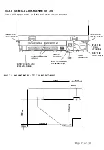
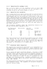
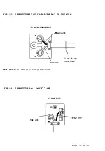
Run a 6 wire cable to the ex change l ine or host PBX
connection p o int and terminate on the exchange l ine
terminal strips in the CCU as shown in f ig.3.3.
3.3.2
Connecting the extensions
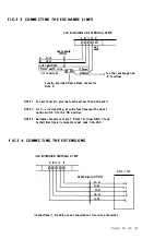
Run
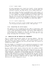
a separate 6 wire cable from the CCU to each extension
position and terminate the cable as shown in f ig.3.4, it is
recommended that all six wires are terminated in the l ine
jack.
Extensions with key modules use 5 wires of the cable
and extensions without key modules use only two wires of the
cable .
If more convenient a larger paired cable may be
provided to a central po int, and the individual extension
cables rad iated out from there.
To comply with the current
regulations the extensions must not share the same cables as
any other circuits.
The following schedule shows the connection details for
British Telecom Cable Equipment 2503-.
CCU Extension
connections
A
B
c
D
E
Wire colour
W-B
B -W
W-0
G-W
W-G
LJU-/lA
connections
5
2
4
1
6
Circu it
Speech 'A'
Speech 'B'
Ov
Key signals
LED signals
The loop resistance of the extension cables must not exceed
that stated for the various approved telephones in the
systems PXML.
The majority of the telephones are approved
for a loop resistance of 50 ohms,
as a gu ide this is
equivalent to 300 metres of 0.5 copper cable.
3.3.3
Functional Earth Connection
The system only requ ires an earth when it is connected to a
host PBX requiring earth signalling.
Where exchange line
surge protection is required external protective devices must
be provided .
Fig.3.3 shows the earth connection details.
Provide a l.5mm2
insulated earth cable from a proven building earth point to
the CCU.
Terminate the earth wire in a locally provided 5-
amp block connector, and provide a 0.5 mm2 insulated wire
from the connector to each of the 'D' terminals on the
exchange line terminal strips.
Suitable connectors are
the
B.T
Block Terminal 58A/12 and Farnell Electronic Components
order code 146-260.
The earth connection should be confirmed using a Line E arth
Loop Impedance Tester.
The impedence of the earth connection
must not exceed 4 ohms.
Page
9
of 33
Summary of Contents for ESCORT
Page 1: ...ESCORT 2 6 ...
Page 2: ......
Page 3: ...BRITISH TELECOM CUSTOMER PREMISES EQUIPMENT E S C 0 R T S Y S T E M MA NUAL Page 1 of 33 ...
Page 36: ......


