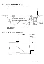
The f ront cover of the CCU is in two parts, for on-site
installation and maintenance only the lower cover needs to be
removed.
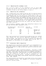
Loosen the two large recessed screws on the front of
the unit and remove the lower cover.
Remove the cross-headed securing screw adjacent to the bottom
right hand corner of the lower PCB, and
release the mounting
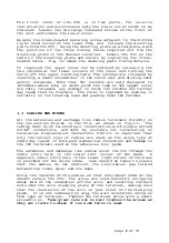
p late from the CCU. Using the mounting plate as a template, mark
the position of the three fixing holes required and fix the
mounting plate in the chocsen location.
Locate the CCU on the
tabs of the mounting plate and secure by replacing the cross
headed screw.
Fig. 3.2 shows the mounting plate fixing details.
If required the upper cover can be removed by releasing the
two catches at the lower corners of the cover and lifting the
cover off the upper locating tabs. The catches are released by
inserting a small screwdriver in the catch slot and sliding them
gently outwards. Note that the catches are only designed to
withdrawn about 6mm, at which point the lugs on the uppper cover
are fully released, any attempt to force the catches out further
may cause them to fracture.
The cover is replaced by seating it
correctly on the locating tabs and pushing home the catches.
3.3
CABLING AND WIRING
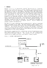
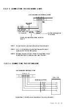
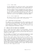
All the extension and exchange line cables terminate directly on
the connection blocks in the CCU,
as shown in fig.3.1.
The
cable
�
must be of twisted pair construction with single strand
0.5mm
conductors,
and must be suitable for terminating on
Insulation Displacement Connectors (IDC).It is important that
only the correct type of cables are used, as the wrong type of
cable may result in both poor mechanical connection and damage to
the IDC terminals used on the extension line jacks.
The extension and exchange line cables enter the CCU through the
cable entry hole in the lower left corner of the base.
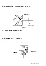
A
separate cable entry hole in the lower right corner of the base
is provided for the mains cable.
Care should be taken to ensure
that the cables do not obstruct the ventilation gap formed
between the lower cover and the base.
Strip the sheaths of the cables so that only about 20mm of the
sheath enters the CCU.
The wires are terminated by stripping
about 6mm of the insulation off the wire, and inserting the bare
end under the wire clamping plate of the terminal, making sure
that the insulation of the wire is just clear of the clamping
plate.
It is not necessary to wrap the wire around the screw on
this type of terminal.
Tighten the terminal screw with a small
screwdriver.
Take great care not to over tig hten the screws as
they are liable ·to shear if too much force is used.
Page
8
of 33
Summary of Contents for ESCORT
Page 1: ...ESCORT 2 6 ...
Page 2: ......
Page 3: ...BRITISH TELECOM CUSTOMER PREMISES EQUIPMENT E S C 0 R T S Y S T E M MA NUAL Page 1 of 33 ...
Page 36: ......


