background image


CJWinter                                                                                   Page 10


4.


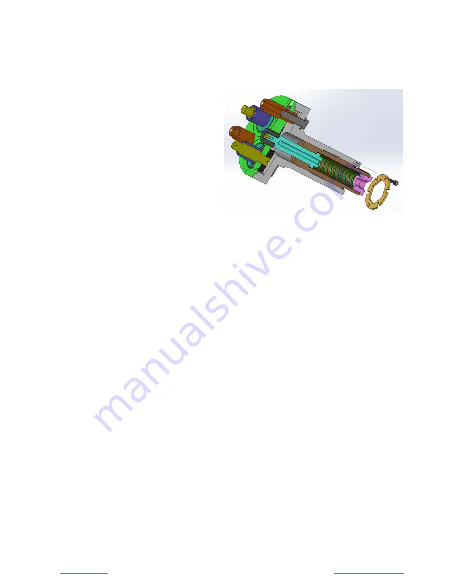
Unlock the Adjusting Sleeve (#14) by removing the #8-32 SHCS (#21) and 
the Spline Brake (#19) at the 
rear of the Shank (#6).  

5.


Add backlash to the gear 
train by unthreading the 
Adjusting Sleeve (#14) until 
the top of master pinion is 
protrudes roughly 3/16" 
above flush with the top of 
the Center Plate (#3). 

6.


Make sure the Thrust Washers (#11 & #22), Thrust Bearings (#10), 
Eccentric Roll Pins (#20) and the Carbide Bushings (#5) all are freshly 
oiled, and free from any contaminants.  

7.


Oil the ID and faces of the knurl rollers, and slide them onto the Carbide 
Bushings/Eccentric Roll Pins. 

8.


Reassemble Front Plate (#1). 

9.


Turn the Adjusting Sleeve (#14) in, to tighten the backlash until the rolls 
just bind, and then back off slightly until they rotate freely.  Lock the 
backlash adjustment by re-installing the Spline Brake (#19) and #8-32 
SHCS (#21). 

Note: Step #9 can be delayed if you need to adjust part size, as it will just 
need to be repeated again later.


Summary of Contents for CJWINTER 192 Series

Page 1: ...192 Series Precision Involute Knurl Spline Tools Instruction Manual ...

Page 2: ...Series Tool Size and Capacity 6 Package Contents 7 Machine Mounting 7 Assembling the Tool 8 Periodic Maintenance 9 Preparing the Tool 9 Pre Setting the Knurl Diameter 11 Shifting the Size Adjustment Range 12 Work Piece Blank Preparation 14 Work Piece Materials 14 The Knurling Procedure 15 Ordering Parts 15 Assembly Drawing 16 Legal Disclosure 17 Contact Information 17 ...

Page 3: ...between the shaft and the over pressed component Why Roll Involute Knurl Connections Involute Knurl connections can be manufactured by a wide variety of means including casting forging cutting broaching milling etc However none of these processes can match the speed at which rolling can form a knurl the economy of the process the convenience of performing the operation in a traditional metalworkin...

Page 4: ...ngineering staff is always available to assist with any technical manufacturing situation The CJWinter 192 Series tools and rolls have incorporated unique Patent Pending features and advantages not always found on other knurl tools 1 Twist Size Adjustment The CJWinter tools requires the loosening of only 3 locking screws and a simple twist of the head to adjust the distance between the 3 knurling ...

Page 5: ...edge wears out you can get twice the life out of each set of tools Retractable Master Pinion The master pinion is spring loaded and can be pushed back into the head by the rotating end of the work piece to allow for knurls on the work piece that are longer than the workface width of the rolls As the master pinion is pushed back it disengages from the knurl rolls and as the work piece is withdrawn ...

Page 6: ...l includes most parts in the following ranges Knurl Major Diameter Ø0 630 min to Ø1 250 max Knurl Lengths up to 813 all diameters 2 0 for Ø 80 or less Typical Involute Pitches 16 D P to 128 D P Note Not all pitches can be rolled on all size parts without interference Contact CJWinter engineering for an evaluation of your application ...

Page 7: ...ith a standard 2 00 shank Alternate shank diameters are available on a custom order basis Drill bushings can also be used to adapt to larger tool holders Shanks are roughly 4 long and have an additional 1 protrusion for the coolant hook up and backlash adjusting screw Most CNC lathes have more than adequate clearance behind the tool holder to accommodate the entire length of this tool and this too...

Page 8: ... for an exploded view and proper part assembly order Please note should you need to disassemble the gear train for the 3 eccentric roll pins proper orientation at re assembly is critical to ensure the rolls are concentric to the tool shank See detailed instructions in the section titled shifting the size adjustment range for the recommended disassembly and re assembly procedure ...

Page 9: ...a preventative manner At a minimum we recommend replacement of these components during the annual inspection The remaining components are not generally considered wear parts and should be replaced only in the event of damage or excessive wear Preparing the Tool To install the appropriate knurl rolls follow these simple steps 1 Remove the three Low Head Cap Screws 8 from the Front Plate 1 2 Pull th...

Page 10: ...0 Eccentric Roll Pins 20 and the Carbide Bushings 5 all are freshly oiled and free from any contaminants 7 Oil the ID and faces of the knurl rollers and slide them onto the Carbide Bushings Eccentric Roll Pins 8 Reassemble Front Plate 1 9 Turn the Adjusting Sleeve 14 in to tighten the backlash until the rolls just bind and then back off slightly until they rotate freely Lock the backlash adjustmen...

Page 11: ...ts 9 a 1 2 turn using a 9 16 open end wrench 2 Twist the head of the tool relative to the shank The graduated scale on the side will tell you if you are adjusting the part size up or down 3 Lock the size by tightening the three hex head bolts Note When running the knurls with little to no backlash it is advisable to add backlash by loosening the Adjusting Sleeve 14 before adjusting part size downw...

Page 12: ...rust Washers 11 22 Thrust Bearings 10 and the Carbide Bushings 5 from the body of the tool 2 Place the tool face DOWN Shank UP on a workbench 3 Loosen the three hex head bolts 9 approximately a 3 16 3 turns using a 9 16 open end wrench 4 Twist the head relative to the shank until the graduated scale on the side reads approximately ZERO 5 Lay the tool on its side and slide the Shank 6 back away fro...

Page 13: ...rt twist the Shank so that the Zero timing mark on the Shank slides towards the side of the scale skipping 1 or 2 gear teeth Twist towards the side of the scale if you need to shift the range to make a smaller part 10 Carefully re engage the ring gear on the Shank 6 with the three Eccentric Gears 4 and slide the Center Plate 3 and Shank 6 back together This will push the three locking pins back ou...

Page 14: ...e tolerance on the finished knurl major diameter Adjustments made to the blank diameter should be small since there is a roughly 3 to 1 relationship between blank diameter and the finished major diameter The knurl can extend into an undercut or terminate right on the blank diameter prior to a shoulder It should be noted that each knurl roll has a lead on chamfer Unless a sufficient undercut is pre...

Page 15: ...ger than the minor diameter of the knurl you will be rolling Run a trial part on an undersized blank prepared per the section entitled Work Piece Blank Preparation and adjust the die opening downwards until proper pitch diameter size is obtained Then adjust the blank size upwards until proper major diameter and die fill is obtained Make blank diameter size changes slowly as adjustments to the blan...

Page 16: ...Assembly Drawing ...

Page 17: ...chine Technologies Inc and is protected under U S Copyright Laws Reproduction in part or in whole is permitted by written authorization ONLY Contact Information 167 Ames Street Rochester NY 14611 p 800 288 7655 f 585 429 5095 http cjwinter com CJWinter Machine Technologies Inc is a Brinkman Products company Brinkman Products is a part of the Brinkman International Group Please visit all of our com...

Reviews: