background image

Not for 

Reproduction

46

www.SnapperPro.com

Regular Maintenance

WARNING

Any procedure other than the proceeding could result in:
 1.  Personal injury caused by electrolyte squirting out of 

the battery vents.

 2.  Personal injury or property damage due to battery 

explosion.

 3.  Damage to the charging system of the booster vehicle 

or of the immobilized vehicle.

Do not attempt to jump start a vehicle having a frozen 
battery because the battery may rupture or explode.  If a 
frozen battery is suspected, examine all fill vents on the 
battery.  If ice can be seen or if the electrolyte fluid cannot 
be seen, do not attempt to start with jumper cables as 
long as the battery remains frozen. 

WARNING

For your personal safety, use extreme caution when 
jump starting.

•  Never expose battery to open flame or electric 

spark—battery action generates hydrogen gas which is 
flammable and explosive.  

•  Do not allow battery acid to contact skin, eyes, fabrics 

or painted surfaces.  Batteries contain a sulfuric acid 
solution which can cause serious personal injury or 
property damage.

•  When removing or installing battery cables, disconnect 

the negative cable first and reconnect it last.  If not done 
in this order, the positive terminal can be shorted to the 
frame by a tool.

•  To avoid engine damage, do not disconnect the battery 

while engine is running.  Be sure terminal connections 
are tight before starting.

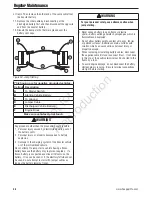
A

C

B

D

D

A

E

F

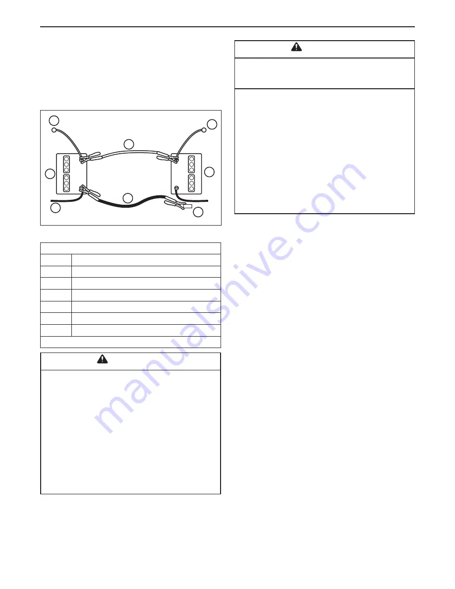
This hook-up is for negative grounded vehicles.

Callout Description

A

To Starter Switch

B

Starting Vehicle Battery

C

To Ground

D

Jumper Cable

E

Discharged Vehicle Battery

F

Engine Block

Make sure vehicles do not touch.

Figure 53. Jump Starting

or frame. Then remove the other end of the same cable from 

the booster battery.

 11. Remove the other cable by disconnecting at the 

discharged battery first and then disconnect the opposite 
end from the booster battery.

 12. Discard the damp cloths that were placed over the 

battery vent caps.

Summary of Contents for 5900654

Page 1: ... una copia póngase en contacto con su distribuidor Snapper Pro o www snapperpro com BRIGGS STRATTON POWER PRODUCTS GROUP LLC 5375 NORTH MAIN STREET MUNNSVILLE NY 13409 800 933 6175 5101740 Rev L Operator s Manual S800X Series Zero Turn Riding Mower Tractor Model Number Description 5900654 S800XB32 5900658 S800X28KAV Mower Deck 5900656 S800X 61 61 Mower Deck 5900875 S800X72 72 Mower Deck ...

Page 2: ... instructions in this manual your Snapper Pro product will provide many years of dependable service This manual contains safety information to make you aware of the hazards and risks associated with this machine and how to avoid them This machine is designed and intended to be used and maintained according to the manual and operated by trained professionals for finish cutting of established lawns ...

Page 3: ...pect Muffler and Spark Arrester 30 Engine Maintenance 30 Lubrication 30 Servicing the Mower Blades 32 Check Hydraulic Oil Level 34 Change Hydraulic Oil Filter 34 Ground Speed Control Lever Adjustment 35 Speed Balancing Adjustment 35 Neutral Adjustment 36 Return to Neutral Adjustment 37 Parking Brake Adjustment 37 Deck Lift Rod Timing Adjustment 38 Deck Leveling Adjustment 39 PTO Clutch Belt Replac...

Page 4: ... with the equipment you have chosen ask a professional contact your local authorized dealer Read the Manual The operator s manual contains important safety information you need to be aware of BEFORE you operate your unit as well as DURING operation Safe operating techniques an explanation of the product s features and controls and maintenance information is included to help you get the most out of...

Page 5: ...g mower blades These blades can pick up and throw debris that could seriously injure a bystander Be sure to clean up the area to be mowed and remove objects that could be thrown by the blade BEFORE you start mowing Do not operate this unit without the entire grass catcher or discharge guard deflector in place Also do not allow anyone in the area while the unit is running If someone does enter the ...

Page 6: ...wn Raise the roll bar as soon as clearance permits Retaining Walls Drop offs and Water Retaining walls and drop offs around steps and water are a common hazard Give yourself a minimum of two mower widths of clearance around these hazards and hand trim with a walk behind mower or string trimmer Wheels dropping over retaining walls edges ditches embankments or into water can cause rollovers which ma...

Page 7: ...e extremely flammable Do not smoke while operating or refueling Do not add fuel while engine is hot or running Allow engine to cool for at least 3 minutes prior to adding fuel Do not add fuel indoors in an enclosed trailer garage or any other enclosed area that is not well ventilated Gasoline spills should be cleaned up promptly and before operation begins Gasoline should be stored only in sealed ...

Page 8: ...top blades if not mowing 22 Use care when loading or unloading the machine into a trailer or truck TRAINING 1 Read understand and follow all instructions in the manual and on the unit before starting If the operator s or mechanic s can not read English it is the owner s responsibility to explain this material to them 2 Become familiar with the safe operation of the equipment operator controls and ...

Page 9: ...ing on slopes See attaching a trailer under OPERATION 3 Never allow children or others in or on towed equipment 4 On slopes the weight of the towed equipment may cause loss of traction and loss of control 5 Travel slowly and allow extra distance to stop 6 Do not shift to neutral and coast down hill CHILDREN Tragic accidents can occur if the operator is not alert to the presence of children Childre...

Page 10: ...ing Do not store fuel near flames or drain indoors 6 Keep all hardware especially blade attachment bolts tight and keep all parts in good working condition Replace all worn or damaged decals 7 Never tamper with safety devices Check their proper operation regularly 8 Disengage drives lower implement set parking brake stop engine and remove key or disconnect spark plug wire Wait for all movement to ...

Page 11: ... or by drilling additional holes BEFORE FIRST TIME USE Inspect the ROLL BAR structure and mounting hardware for 1 Check to make sure the machine GVW Gross Vehicle Weight including attachments restrained payload fuel and operator is not in excess of the maximum weight specified on the ROLL BAR label 2 Make sure there isn t any missing damaged or loose mounting hardware 3 Make sure the ROLL BAR has ...

Page 12: ... the seat belt does not pass all of the following tests it should be replaced BEFORE EACH USE Conduct the following inspections maintenance of the seat belt and retraction mechanism 1 Check for dirt or debris in the retraction mechanism If dirt or debris is found it should be removed 2 Check to make sure the retraction mechanism retracts easily and completely 3 Check for damage to any part of the ...

Page 13: ...nd follow all safety decals 15 Max WARNING If any safety decals become worn or damaged and cannot be read order replacement decals from your local dealer DANGER Amputation and thrown objects hazard Keep hands and feet away from deck Do not operate mower unless discharge chute or entire grass catcher is in its proper place 7101665 A B C D E F A B C B F D E C E G G G This decal is located behind the...

Page 14: ...evers are not in the NEUTRAL position OR Test 2 Engine SHOULD crank if PTO switch is NOT engaged AND Parking brake is engaged AND Ground speed control levers are locked in the NEUTRAL position AND Test 3 Engine should SHUT OFF if Operator rises off the seat with the PTO engaged OR Operator rises off the seat with the parking brake disengaged Operator moves the ground speed control levers out of th...

Page 15: ...tions shown NOTE For location of engine identification numbers refer to engine owner s manual SAM PLE SAM PLE North American Models Mower Deck Identification Tag Tractor Identification Tag Safety Icons A B C D E F G H I J K L M N O P Callout Description A Alert B Read the Manual C Amputation Rotating Parts D Pinch Point E Fire Hazard F Amputation Hand in Blade G Amputation Foot in Blade H Thrown O...

Page 16: ...ols the right drive wheel Moving a lever forward increases the FORWARD speed of the associated wheel and pulling back on and lever increases the REVERSE speed Note The further a lever is moved away from the neutral position the faster the drive wheel will turn See Zero Turn Driving Practice section for steering instructions Seat Adjustment Lever The seat can be adjusted forward and back S N 201464...

Page 17: ...the engine to run and powers the electrical system START Cranks the engine for starting Note Never leave the ignition switch in the RUN position with the engine stopped this drains the battery Choke Close the choke for cold starting Open the choke once the engine starts A warm engine may not require choking Pull the knob UP to close the choke Push the knob DOWN to open the choke Throttle Control T...

Page 18: ... bystanders WARNING Never allow passengers to ride on the unit Before leaving the operator s position for any reason engage the parking brake disengage the PTO stop the engine and remove the key To reduce fire hazard keep the engine tractor and mower free of grass leaves and excess grease Do NOT stop or park tractor over dry leaves grass or combustible materials Gasoline is highly flammable and mu...

Page 19: ...k the hydraulic oil tank C and make sure that the oil level is up to the FULL COLD mark Adjust the height of the mower deck to the desired position See Mowing Height Adjustment Adjust the seat position and make certain you can reach all controls from the operator s position Make sure that the fuel valve D is in the ON position Figure 2 Seat Adjustment A Seat Adjustment Lever S N 2014648787 Below B...

Page 20: ...crements 1 Turn the ignition key C to the RUN position 2 Press the mower deck lift actuator switch B foward away from the operator to remove the pressure from the deck height adjustment pin 3 Place the deck height adjustment pin in the desired location 4 Press the mower deck lift actuator switch backwards towards the operator until contact is made with the deck height adjustment pin Continue to re...

Page 21: ...emove the key Safety Interlock and Mower Deck Positioning Instructions This unit is equipped with an safety interlock system to help keep the operator safe while running the unit Please read and understand the SAFETY INTERLOCK SYSTEM and FEATURES AND CONTROLS sections before attempting to drive or operate the mower In order for the unit to operate properly the controls must be in the correct posit...

Page 22: ...ake prior to moving the control levers inward Basic Driving Forward Travel Practice Gradually move both ground speed control levers evenly FORWARD from neutral Slow down and repeat NOTE Straight forward travel takes practice If necessary top speed can be balance adjusted see the Speed Balancing Adjustment in the Adjustments section near the back of this manual Reverse Travel Practice LOOK DOWN BEH...

Page 23: ...ore familiar and experienced with operating the Zero Turn rider you will learn more maneuvers that will make your mowing time easier and more enjoyable Remember the more you practice the better your control of the Zero Turn will be Practice Turning Around a Corner While traveling forward allow one handle to gradually return back toward neutral Repeat several times NOTE To prevent pivoting directly...

Page 24: ... to cut no more than one third of the grass height and never more than 1 inch at a time The amount of grass you are able to cut in one pass is also effected by the type of mowing system you are using for example broadcasting with side discharge decks can process a much larger volume of grass than mulching does Tall Grass Requires Incremental Cutting For extremely tall grass set the cutting height ...

Page 25: ... too fast using a slower ground speed will improve the cutting efficiency of the blades and prevents many common cutting problems Use an appropriate ground speed for the thickness and height of the grass you are cutting 3rd gear or slower for manual gear models If you hear the engine slowing down you are mowing too fast use a slower ground speed Where possible make one or two passes around the out...

Page 26: ...and the appropriate amount is cut Do not use the mower as a mulching mower during the first two or three mowings in the spring The long grass blades quick growth and often wetter conditions are more suitable for broadcasting side discharging or grass bagging operation Mulching Action Engine Speed Ground Speed for Broadcasting Use full engine throttle matched with a slow ground speed so that clippi...

Page 27: ...ise the roll bar C until the rubber stops D contact the upright tubes 3 Push or pull the top of the roll bar forward against the rubber stops and reinstall the retainer pins and hair pin clips to secure the roll bar in the raised position Figure 12 Raise Lower the Roll Bar A Hair Pin Clip B Retainer Pin C Roll Bar D Rubber Stop C B A D D C WARNING Avoid serious injury or death from roll over Keep ...

Page 28: ... point F 2 Extend the actuator until the front wheels contact the ground 3 Reinstall the pins with lanyards through the rear hole G of the attachment latches D 4 Extend the actuator until the load is removed from the actuator Turn the ignition key to the OFF position 5 Raise the seat and disconnect the actuator wire harness A Figure 14 on the right side of the machine by rotating the connector dia...

Page 29: ...xtend the actuator fully 2 Install the pins with lanyards into the attachment lift arms A Figure 13 3 Reposition the cutting height adjustment pin to the desired cutting height 4 Retract the actuator until contact is made with the cutting height adjustment pin A Figure 17 Continue to retract the actuator until the operating position indicator lamp B stops flashing and shuts off NOTE The actuator M...

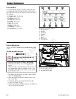
Page 30: ...g Fall Check Rider Mower for loose hardware Clean Deck Check Replace Mower Blades Lubricate Rider Mower Clean Battery Cables Check Tire Pressure Check Hydraulic Oil Level Change Hydraulic Oil Filter Check Gearbox Oil Level Engine Maintenance Before Each Use Every 5 Hours Every 25 Hours Every 100 Hours Every 250 Hours Spring Fall Check Engine Oil Level Check Clean Cooling Fins Intake Service Air Fi...

Page 31: ...om the oil drain hose A and drain the engine oil into the pan 4 After draining replace the cap and wipe up any spilled oil Route the oil drain through the hose clamp and towards the rear of the machine so the oil drain hose is retained during normal operation 5 Place an absorbent shop cloth under the engine oil filter D Remove the engine oil filter and replace with a new one 6 Remove the engine oi...

Page 32: ... spindles idler arm rear pivoting axle hydraulic pump drive and PTO clutch idler arms Use grease fitting when present Disassemble parts to apply grease to moving parts when grease fittings are not installed Not all greases are compatible Red grease p n 5022285 is recommended automotive type high temperature lithium grease may be used when this is not available Oil control handle pivots seat plate ...

Page 33: ... Figure 21 Control Handle Pivots Seat Plate Pivot A B Figure 22 Idler Arms A PTO Clutch Drive Belt Idler Arm B Hydraulic Pump Drive Belt Idler Arm Figure 24 Attachment Lift Arms Actuator Figure 25 Deck Lift Rods Figure 23 Mower Deck Lubrication Points ...

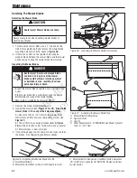
Page 34: ...not sharp or have nicks sharpen the blades See Sharpening the Mower Blades Figure 26 Loosening the Mower Blade for Removal Figure 27 Inspecting the Mower Blade Tips A Mower Blade Cutting Edge B Square Corner C Air Lift D Wear Measurement DISCARD Mower Blade If greater than 5 12 7 mm B D A B C Figure 28 inspecting the Mower Blade Air Lifts A New Mower Blade B Mower Blade at Wear Limit A notch begin...

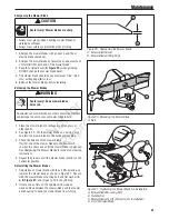
Page 35: ...at the process until the mower blade remains in the horizontal position Reinstalling the Mower Blades 1 Reinstall each mower blade with the air lifts pointing up towards the mower deck as shown in Figure 31 Secure with the mower blade mounting bolt and flat washer A B Figure 31 and torque to 70 ft lbs 94 Nm 2 If there are no flats on the spindle shaft wedge a wooden block between the mower blade a...

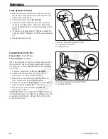
Page 36: ...l the reservoir cap Change Hydraulic Oil Filter Change Interval Every 250 hours Filter Part Number 1719168 NOTE Removing the oil filter from the filter base will drain the oil reservoir Have a suitable container ready to catch any spilled oil It is recommended that this be a dealer only service item 1 Locate the transmission oil filter A Figure 33 2 Lubricate the new filter base with a few drops o...

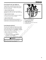
Page 37: ...the lever s C to align with each other To Adjust the Handle Placement Loosen the jam nuts and adjust the placement bolt B in or out to properly adjust the lever end spacing To Adjust the Handle Height Remove the mounting hardware D and reposition the handle either up or down from its original position You will need to readjust the handle alignment as described above Speed Balancing Adjustment If t...

Page 38: ... creeps forward turn the rod CLOCKWISE while standing at the rear of the machine facing forward If the machine creeps backward turn the rod COUNTER CLOCKWISE while standing at the rear of the machine facing forward 3 Lock the jam nut D against the ball joint B when neutral is achieved 4 Start the engine 5 Disengage the parking brake and lock the ground speed control levers in the neutral position ...

Page 39: ... levers in neutral 3 Tighten the set collar snug against the return spring 4 Pull the ground speed control levers rearward and release to check that the lever stops aligned with the notch in the neutral lock plate NOTE It is important to note that after every adjustment of the neutral return spring the lever must be returned to the locked position to properly check the neutral position Parking Bra...

Page 40: ...ack rod pivots are NOT straight up and down adjustment is required continue with Step 4 4 Block up the mower deck up until all hanger chains are slack Refer to Figure 40 5 See Figure 41 To adjust the lift rod loosen the jam nut B Figure 41 on the front clevis C and then remove the 1 2 clevis pin fastening the clevis to the lift pivot arm Turn the clevis CLOCKWISE to cause the rod pivot to pivot ba...

Page 41: ...ck with the 3 1 2 sides being vertical See Figure 42 4 Loosen the nuts A Figure 43 and allow the front of the deck to rest on the 2 x 4 s Slide the chains down in the slots until the chains are tight and tighten the nuts See Figure 43 5 Loosen the nuts A and allow the rear of the deck to rest on the 2 x 4 s Slide the chains down in the slots until the chains are tight and tighten the nuts See Figu...

Page 42: ...the belt on the drive shaft pulley Carefully release the tension on the breaker bar 8 Re install the PTO clutch anchor bolt 9 Close the hood and secure with the hood latches 10 Run the mower under no load condition for about 5 minutes to break in the new belt D C A E B F Figure 46 PTO Clutch Belt Replacement A PTO Clutch Belts B PTO Clutch Anchor Bolt C Idler Arm D Drive Shaft Pulley E PTO Clutch ...

Page 43: ...break in the new belt Mower Belt Replacement NOTICE To avoid damaging belts do NOT pry belts over pulleys 1 Park the tractor on a smooth level surface such as a concrete floor Disengage the PTO engage the parking brake turn off the engine and remove the ignition key 2 Lower the mower deck to its lowest cutting position and remove the mower deck guards WARNING Spring loaded components can kick back...

Page 44: ...load condition for about 5 minutes to break in the new belt Check the Mower Belt Idler Tensioning Spring Length 72 Models Only 1 Remove the mower deck guards 2 Set the mower deck to the 3 1 2 8 9 cm cutting height 3 Measure the coil length A Figure 49 of the mower belt idler tensioning spring B The measurement should equal 7 1 4 1 8 18 42 cm 32 cm If not perform the Adjust the Mower Belt Idler Ten...

Page 45: ...er 500 hours or 12 months 1 Park the machine on a flat level surface such as a concrete floor Disengage the PTO engage the parking brake turn off the engine 2 Position the mower deck in the highest cutting position 3 Raise the mower deck to the service position See Positioning the Mower Deck for Service 4 Place blocks underneath the mower deck to support the mower deck in the service position 5 Re...

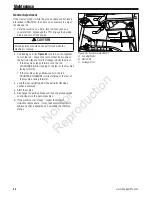
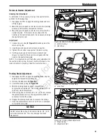
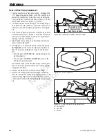
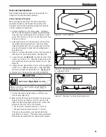
Page 46: ...rks away from the battery Be careful when handling the battery Avoid spilling electrolyte Keep flames and sparks away from the battery When removing or installing battery cables disconnect the negative cable FIRST and reconnect it LAST If not done in this order the positive terminal can be shorted to the frame by a tool Fuse Locations The fuse blocks are located on the side of the instrument contr...

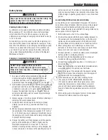
Page 47: ...re the specific gravity of a cell once per hour The battery is fully charged when the cells are gassing freely at low charging rate and less than 0 003 change in specific gravity occurs over a three hour period Jump Starting With Auxiliary Booster Battery Jump starting is not recommended However if it must be done follow these directions Both booster and dis charged batteries should be treated car...

Page 48: ...ammable and explosive Do not allow battery acid to contact skin eyes fabrics or painted surfaces Batteries contain a sulfuric acid solution which can cause serious personal injury or property damage When removing or installing battery cables disconnect the negative cable first and reconnect it last If not done in this order the positive terminal can be shorted to the frame by a tool To avoid engin...

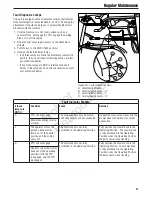
Page 49: ... Module B Fault Indicator Lamp A C Fault Indicator Lamp L D Fault Indicator Lamp C Fault Indicator Module If these lamps are NOT lit Condition Cause Remedy C PTO will not engage The main wire harness and mower deck wire harness are not connected Inspect the main wire harness and the mower deck wire harness for proper connection Mower deck will not raise or lower L The operator moves the ground spe...

Page 50: ... once a month If battery is left in unit disconnect the negative cable 10 Drain fuel system completely or add a gasoline stabilizer to the fuel system If you have chosen to use a fuel stabilizer and have not drained the fuel system follow all safety instructions and storage precautions in this manual to prevent the possibility of fire from the ignition of gasoline fumes Remember gasoline fumes can...

Page 51: ...SED position 5 Replace fuse 6 Clean the battery terminals 7 Recharge or replace 8 Visually check wiring replace broken or frayed wires Tighten loose connections 9 Repair or replace See authorized dealer 10 Replace as needed See authorized service dealer 11 Clean and gap or replace See engine manual 12 Drain fuel replace with fresh fuel 13 Drain fuel replace with fresh fuel Engine starts hard or ru...

Page 52: ...he parking brake 3 Sit in the seat Troubleshooting the Mower PROBLEM CAUSE REMEDY Mower will not raise 1 Lift linkage not properly attached or damaged 1 See authorized service dealer for repair Engine stalls easily with mower engaged 1 Engine speed too slow 2 Ground speed too fast 3 Cutting height set too low 4 Discharge chute jamming with cut grass 1 Set to full throttle 2 Decrease ground speed 3...

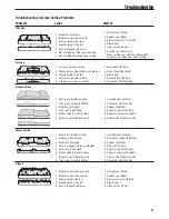
Page 53: ...eled correctly 2 Tires are not properly inflated 3 Blades are damaged 4 Deck shell is damaged 5 Mower spindle is bent or loose 6 Blades are installed incorrectly 1 Level the deck correctly 2 Check and inflate the tires 3 Replace the blades 4 Repair or replace the deck 5 Repair or replace the spindle 6 Reinstall the blades correctly Uneven Cutting 1 Deck is not leveled correctly 2 Blades are dull o...

Page 54: ...affected by among other things ambient operating conditions and engine to engine variability Given the wide array of products on which engines are placed the gasoline engine may not develop the rated gross power when used in a given piece of power equipment This difference is due to a variety of factors including but not limited to the variety of engine components air cleaner exhaust charging cool...

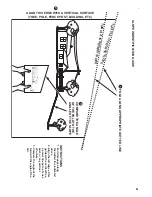
Page 55: ...uide with a vertical tree a power line pole a fence post or any vertical structure 3 Compare the angle of the fold with the angle of the hill SLOPE INDENTIFICATION GUIDE ALIGN THIS EDGE WITH A VERTICAL SURFACE TREE POLE FENCE POST BUILDING ETC COMPARE THE ANGLE OF THE FOLD TO THE ANGLE OF THE SLOPE 2 3 T H I S I S A 1 0 D E G R E E S L O P E FOLD ALONG APPROPRIATE DOTTED LINE 1 ...

Page 56: ...N o t f o r R e p r o d u c t i o n Notes ...

Page 57: ...We welcome warranty repair and apologize to you for being inconvenienced Warranty service is available only through SNAPPER PRO Authorized Service Dealers Most warranty repairs are handled routinely but sometimes requests for warranty service may not be appropriate This warranty only covers defects in materials or workmanship It does not cover damage caused by improper use or abuse improper mainte...

Page 58: ...N o t f o r R e p r o d u c t i o n Operator s Manual S800X Series Zero Turn Riding Mower ...

Reviews: