background image

8 / 28

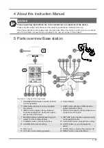
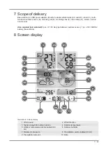
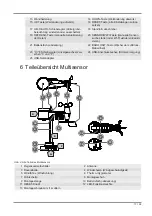
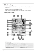
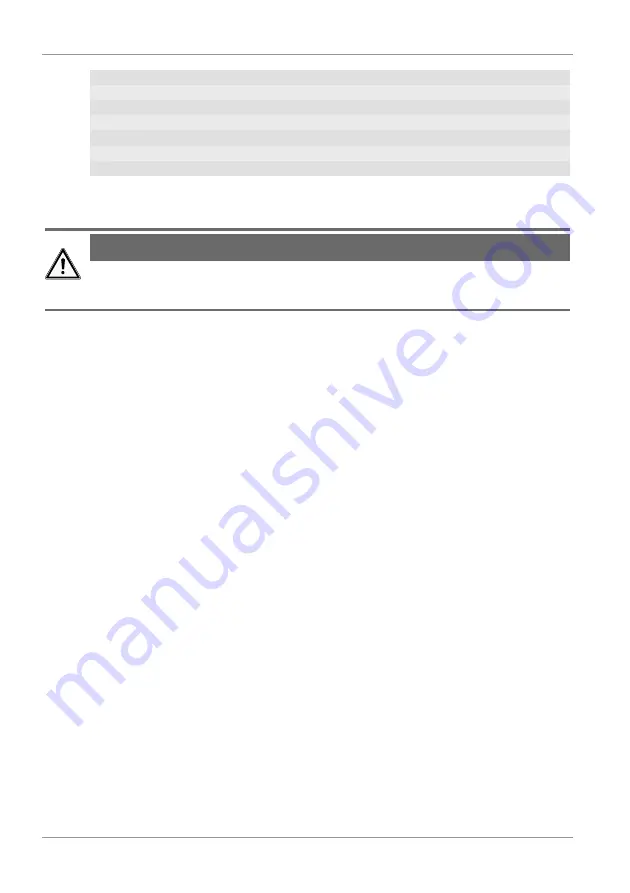
11 WIFI synchronization

12 Ice alert enabled

13 Wake-up alarm enabled

14 Current time

15 Temperature felt

16 Moon phase

17 Weekday

18 Graphical weather trend display

19 Indoor humidity

20 Comfort indicator (climate)

21 Indoor temperature alarm enabled

22 Indoor temperature

23 Trend arrow (rising, constant or falling)

9 Before starting operation

NOTICE

Avoid connectivity disruptions!

To avoid connectivity disruptions between the devices, consider the following points before starting
operation.

1. Place base station (receiver) and remote sensor (sender) together as close as possible.

2. Set up power supply for the base station and wait until the indoor temperature is displayed.

3. Set up power supply for the remote sensor.

4. Position the base station and the remote sensor within the effective transmission range.

5. Ensure that the base station and remote sensor are assigned to the same channel.

When changing batteries always change batteries in the main unit as well as all remote units and re-
place them in the correct order, so the remote connection can be re-established. If either of the
devices is mains-powered, the power supply must be disconnected for a short moment also for this
device when exchanging the batteries. If batteries are exchanged in only one of the devices (i.e. the
remote sensor) the signal can’t be received or can’t be received correctly.

Note, that the effective range is vastly affected by building materials and position of the main and re-
mote units. Due to external influences (various RC devices and other sources of interference), the
maximum distance can be greatly reduced. In such cases we suggest to position the main unit and the
remote sensor at other places. Sometimes all it takes is a relocation of one of these components of a
few inches!

10 First Steps

Follow the bullet points in order, to ensure a successful setup.

• Setting up power supply (base station and wireless sensor)

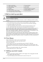
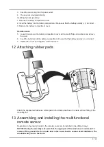
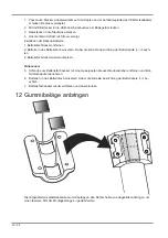
• Mount the remote sensor

• The base station is now in AP mode (LED flashes green) and ready for initial setup.

• Create a Weather Underground account and add the station to your account ("My Profile" / "Add
Weather station"). Here you will receive a station ID and a password, which will be needed in the next
step.

• Setting up the base station (Estabish Wi-Fi / Router connection)

• Viewing weather data via web, mobile or tablet

11 Setting up power supply

Base unit

1. Push the appropriate plug adapter attachment onto the spigot on the mounting plate of the USB

power adapter until it snaps into place.

2. Plug the MicroUSB plug into the USB connection socket on the base unit.

Summary of Contents for Weather Center WTW 5in1

Page 1: ...Weather Station Wetterstation Weather Center WTW 5in1 EN Instruction manual DE Bedienungsanleitung...

Page 2: ...e este producto en un idioma determinado Entonces visite nuestra p gina web utilizando el siguiente enlace c digo QR para ver las versioneAs disponibles IT Desidera ricevere informazioni esaustive su...

Page 3: ...English 4 Deutsch 15...

Page 4: ...e respective companies used in this document are protected by brand patent or product law in Germany the European Union and or other countries 2 Validity information This documentation is valid for th...

Page 5: ...OZE button snooze function or interrupt alarm 2 Colour display 3 RAIN button display of various precipita tion values 4 BARO button display of different atmo spheric pressure values 5 INDEX button dis...

Page 6: ...re measurement unit 23 C F slider display change betw C and F 24 USB socket power supply 25 USB power adapter 6 Parts overview Multisensor 1 3 4 5 6 9 8 7 13 10 11 E D F G 7 8 12 2 Illustration 2 All...

Page 7: ...ed 3 pcs of 1 5V AA type batteries outdoor sensor 1 pc of 3V CR2032 battery base station 8 Screen display 23 2 1 9 10 15 14 18 7 4 21 20 8 22 3 5 6 13 11 12 17 16 19 Illustration 3 Screen display 1 Wi...

Page 8: ...or this device when exchanging the batteries If batteries are exchanged in only one of the devices i e the remote sensor the signal can t be received or can t be received correctly Note that the effec...

Page 9: ...the battery compartment Ensure that the battery polarity is correct 7 Replace the cover and retighten it with the screw 12 Attaching rubber pads Attach the supplied self adhesive rubber pads to the c...

Page 10: ...4 Signal transmission The base station will automatically connect to the multi outdoor sensor and if available to other wire less sensors You can also press the Wi Fi SENSOR button to start a manual s...

Page 11: ...wise the service can not be used 17 Configuration Setting up a WI FI connection 1 If the base station has not yet been connected to a router it will switch to AP Access Point Mode mode after the first...

Page 12: ...button can be pressed for 6 seconds to restore the previous settings WI FI connection status WI FI symbol is shown in the display WI FI symbol flashes in the dis play AP symbol flashes in the display...

Page 13: ...ent value fore the time offset flashes 2 Press up or DOWN button to set the desired hour value 0 to 10 hours for the time offset 3 Finally press the CLOCK SET button for approx 3 seconds to save the s...

Page 14: ...download 7002585 CE 7002585_CE pdf 24 Disposal Dispose of the packaging materials properly according to their type such as paper or card board Contact your local waste disposal service or environment...

Page 15: ...ndeten Bezeichnungen und Markennamen der jeweiligen Firmen sind im Allgemeinen in Deutschland der Europ ischen Union und oder weiteren L ndern waren mar ken und oder patentrechtlich gesch tzt 2 G ltig...

Page 16: ...4 6 5 7 17 19 22 20 9 24 23 18 21 Abb 1 Alle Teile der Basisstation 1 ALARM SNOOZE Taste Schlummerfunk tion oder Alarm unterbrechen 2 Farbdisplay 3 RAIN Taste Anzeige verschiedener Nie derschlagswert...

Page 17: ...i vieren 21 Batteriefach abdeckung 22 BARO UNIT Taste Wechel der Luftdruck Ma einheit 23 C F Schieberegler Anzeigewechsel zwi schen C und F 24 USB Anschlussbuchse Stromversorgung 25 USB Netzadapter 6...

Page 18: ...en 3 St ck 1 5V Batterien Typ AA Au ensensor 1 St ck 3V Batterie Typ CR2032 Basisstation 8 Displayanzeigen 23 2 1 9 10 15 14 18 7 4 21 20 8 22 3 5 6 13 11 12 17 16 19 Abb 3 Displayanzeigen 1 Windgesch...

Page 19: ...uss auch f r die ses bei einem Batteriewechsel kurzzeitig die Stromverbindung getrennt werden Werden z B nur die Batterien im Sensor ausgetauscht kann das Signal anschlie end gar nicht oder nicht mehr...

Page 20: ...fach einsetzen Dabei die korrekte Ausrichtung der Batteriepole beach ten 3 Batteriefachdeckel wieder aufsetzen Funksensor 5 Schraube am Batteriefachdeckel mit einem geeigneten Kreuzschraubendreher ent...

Page 21: ...age an einem vertikal oder horizontal ausgerichteten Rohr 6 Die Schritte 1 bis 4 wie zuvor ausf hren 7 Die Unterseite des Montagefu es auf das Rohr aufsetzen und die Rohrschelle von der anderen Seite...

Page 22: ...ein Key werden durch den Dienst automatisch generiert die f r die folgende Konfiguration der Wetterstation ben tigt werden HINWEIS F r die Registrierung nur eine g ltige E Mail Adresse verwenden da d...

Page 23: ...ss der Einstellungen erkennt das Endger t nach jedem Neustart die voreingestellte W LAN Verbindung wieder 7 Im Access Point Mode kann die WI FI SENSOR Taste 6 Sekunden lang gedr ckt werden um die vorh...

Page 24: ...e ca 2 Sekunden dr cken um zum normalen Anzeigemodus zur ckzukehren 20 Zeitzone einstellen Um eine abweichende Zeitzone einzustellen folgenderma en vorgehen 1 CLOCK SET Taste etwa 3 Sekunden dr cken u...

Page 25: ...elnummer 7002585 der Richtlinie 2014 53 EU entspricht Der vollst ndige Text der EG Konformit tserkl rung ist unter der folgenden Internetadresse verf gbar www bresser de download 7002585 CE 7002585_CE...

Page 26: ......

Page 27: ......

Page 28: ...e mail e mail sav bresser fr T l phone 33 494 592 599 BRESSER France SARL P le d Activit s de Nicopolis 260 rue des Romarins 83170 Brignoles France Prix d un appel local depuis la France ou Belgique S...

Reviews: