background image


MANUAL P/N 900000015 REV 1.2 

22

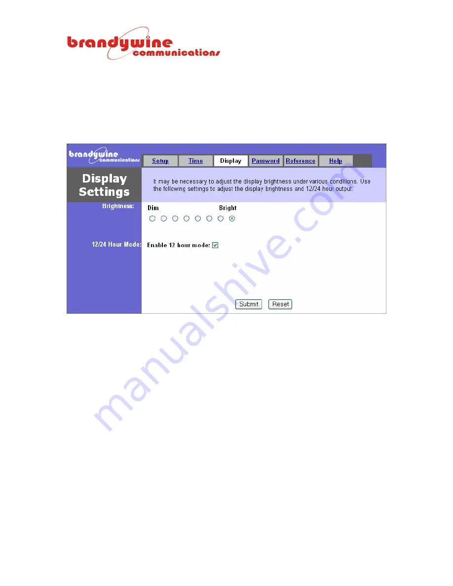
4.3 Display 


The Display tab consists of two sections, the Brightness and 12/24 Hour Mode.  This tab allows 
you to modify display settings for the Network Time Device.  To save all modifications made to the 
display settings, click the Submit button.  To undo all modifications made to the display settings, 
click the Reset button. 


4.3.1 Brightness 

 
The Brightness consists of eight radio buttons from Dim to Bright.  The user may modify the level of 
brightness for the Network Time Device by selecting one of the eight radio buttons. 
 

4.3.2


12/24 Hour Mode 


The 12/24 Hour Mode consists of a check box, the enable 12 hour mode.  If the user clicks the 
check box the time for the Network Time Device will be displayed in 12 hour mode.  If the user 
does not click the check box the time for the Network Time Device will be displayed in 24 hour 
mode.  


Summary of Contents for NTV-100XX

Page 1: ...5 REV 1 2 User Guide Network Time Device Model NTV 100XX P N 06000000X Revision 1 2 May 2005 Brandywine Communications 2230 South Fairview Street Santa Ana CA 92704 714 755 1050 714 755 0175 http www...

Page 2: ...Numbers MODEL PART NUMBER DESCRIPTION NTV 100RK 060000001 Network Time Device Display Rack NTV 100RG 060000002 Network Time Device Display Rack with GPS NTV 100DK 060000003 Network Time Device Display...

Page 3: ...REVISION DATE COMMENTS NC 09 21 04 Original release of the Network Time Device user guide 1 0 10 13 04 Revision of entire user guide 1 1 05 02 05 Added the UDP port used by IPSetup and AutoUpdate 1 2...

Page 4: ...Panel 10 2 3 5 Speed Indicator Rear Panel 10 3 Unpacking and Installation 11 3 1 Unpacking 11 3 2 Installation 11 3 3 Connections 12 3 3 1 Hub Connection Example 12 3 3 2 Modem Connection Example 12 3...

Page 5: ...internal clocks and the reference A second order digital phase lock loop PLL is used to adjust the internal clocks of the Network Time Device to match the time of the reference over long time interva...

Page 6: ...to the Network Time Device Ethernet and connect the other end of the Ethernet cable to a hub 2 1 2 Serial Port Input The Network Time Device may receive time from the Serial Port Input through the Ser...

Page 7: ...er end of the serial cable 1 to the serial port of the modem 1 connect the modem 1 to another modem 2 connect one end of another serial cable 2 to the serial port of the modem 2 and connect the other...

Page 8: ...ght levels of brightness To increase the level of brightness press the Brightness button one time To display the IP address of the Network Time Device press the Brightness button two times Use the sam...

Page 9: ...tton Default Mode Rear Panel To get to the default mode press and hold down the Brightness button for more than ten seconds and all lights in the display window will flicker The default mode will defa...

Page 10: ...k Time Device is currently plugged into an electrical socket by glowing green 2 3 4 Link Indicator Rear Panel The Link Indicator indicates that the Network Time Device is currently connected to a hub...

Page 11: ...o a hub Within a few seconds the IP Address of the device is displayed and the time currently being displayed is automatically corrected 4 Open your Internet browser and type the IP Address of the dev...

Page 12: ...Network Time Device 12 34 Network Time Device Hub 12 34 Network Time Device LAN Hub Network Time Device with GPS server 12 34 Network Time Device Modem Modem 12 34 Network Time Device Modem Modem 12 3...

Page 13: ...pins used by the Network Time Device serial port for RS232 The RS422 Pinout DB 9 Connector Table lists the pins used by the Network Time Device serial port for RS422 RS232 Pinout DB 9 Connector Table...

Page 14: ...the Link Location Drawing and Link Configuration Table Link Location Drawing Link Configuration Table LINK SETTING DESCRIPTION JP1 1 3 RS422 JP1 6 8 RS422 transmit data JP1 8 10 RS422 receive data JP1...

Page 15: ...23 255 255 0 To save all modifications made to the Setup screen click the Submit button To undo all modifications made to the Setup screen click the Reset button 4 1 1 System The System section consis...

Page 16: ...the Network Time Device will retrieve its configurations from the DHCP server If the DHCP Disable radio button is selected the user must manually enter the configurations for the device The Device IP...

Page 17: ...urner IPSetup screen will be displayed 3 Verify that the Select a Unit displays the current MAC and IP address of the NTV connected to the network 4 Click on the NTV that needs to be configured 5 Ente...

Page 18: ...one Settings Daylight Saving Time and Daylight Saving Time Advanced This tab allows you to modify the time settings for the Network Time Device To save all modifications made to the Time Settings scre...

Page 19: ...d Stop Bits follow RS232 standard The Parity enables the user to check the validity of the data by using either odd or even parity checking Format Characters Table CHARACTER DESCRIPTION A AM PM C Carr...

Page 20: ...all time zones and their Standard Time offsets from the Universal Time Time Zone Table TIME ZONE STANDARD TIME OFFSET FROM UNIVERSAL TIME Eniwetok Marshall Islands 12 Samoa Polynesian Islands 11 Hawa...

Page 21: ...either in hours or minutes The Daylight saving start allows the user to add the daylight saving offset to the time the daylight saving should start The user must enter the daylight saving start time...

Page 22: ...click the Reset button 4 3 1 Brightness The Brightness consists of eight radio buttons from Dim to Bright The user may modify the level of brightness for the Network Time Device by selecting one of t...

Page 23: ...the Password screen click the Reset button IMPORTANT INFORMATION Please note that the default user name and password for the system is BRANDYWINE and the user must always enter a user name and passwo...

Page 24: ...e that while the Network Time Device is acquiring time from the reference the colons on the Network Time Device will be flashing Once the Network Time Device has acquired time from the reference the c...

Page 25: ...d descriptions used Serial Time Format Table DATA DESCRIPTION STS Start of the message x02 and this character acts as the 1PPS timing mark DOW Day of the week written as three letters Sun Mon Tue Wed...

Page 26: ...djusting the internal clocks in the NTP servers using the internal Proportional Integral algorithm After the first 300 seconds the NTP client will begin repeatedly querying the server after every quer...

Page 27: ...as access to the Help screen whenever the user encounters a problem Once the user clicks on the help link the user will be automatically redirected to the Help screen Topics discussed in the Help scre...

Page 28: ...me Device Please note that AutoUpdate uses unicast on UDP port 20034 1 Double click on the AutoUpdate icon and the AutoUpdate V2 0 screen will be displayed 2 Enter the IP address of the Network Time D...

Page 29: ...ton The File Name field will be completed for you 4 Now click on the Reboot when complete check box 5 To close the application click the Dismiss button 6 To upload the new firmware click the Update bu...

Page 30: ...Rack Front Panel 2 Network Time Device Display Rack Mechanical Outline 3 Network Time Device Display Desk Front Panel 4 Network Time Device Display Desk Mechanical Outline 5 Network Time Device Displa...

Page 31: ......

Page 32: ......

Page 33: ......

Page 34: ......

Page 35: ......

Page 36: ......

Reviews: