background image

BRAILLO


l

B 650 SF


73

Step 2.


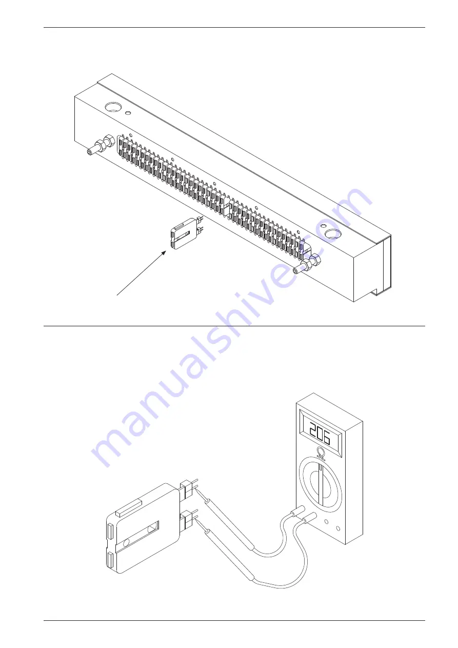
Pull out the defect magnet with, e.g. a narrow pair of “needle nose” pliers.

Magnet

Step 3.


Check the magnets internal resistance if you have an ohm-meter available. The resist-

ance should be between 185 ohm and 240 ohm. Any value outside this range indicates a defective 

magnet.

Summary of Contents for 650 SF

Page 1: ...Rev April 2018 BRAILLO L NORWAY FOR BETTER BRAILLE AND MORE User s Guide BRAILLO 650 SF...

Page 2: ...2018 Braillo Norway AS...

Page 3: ...bility to change with it Our goal is to manufacture a Braille embosser that when properly maintained by following the instructions in this manual will not only last decades but will also produce Brail...

Page 4: ...BRAILLO l B 650 SF 4...

Page 5: ...ent menu choices 39 3 5 Messages Error messages on the Printer operator panel 47 3 6 Test print 51 3 7 Functions Staple and Fold operating panel 52 3 8 Messages in the Staple and Fold display 56 3 9 S...

Page 6: ...Picking paper 123 7 6 Vacuum 124 7 7 Sheet splitter 125 7 8 Stack holders 126 7 9 Staple anvil 127 7 10 Folding 128 7 11 Stapling 129 7 12 Trap door 130 7 13 Eject 131 7 14 Valve ramp 132 7 15 Comple...

Page 7: ...BRAILLO l B 650 SF 7 9 GENERAL INFORMATION 151 9 1 Declaration of conformity 151 9 2 Warranty 152 Warranty request form 153 9 3 Addresses and phone numbers 154...

Page 8: ...ament to their quality To maxi mize the life of your Braillo printer we strongly recommend using the correct tools which come with your printer as well as following the correct procedures which we pre...

Page 9: ...OLL FEEDER PRINTER AND CUTTER STAPLE AND FOLD UNIT Printer overview Please see figure below Note that the right hand and left hand side are referred to as if you were standing behind the Printer facin...

Page 10: ...Cutting Feeding Unwinding Stack of covers Stack of printed sheets Ready book with cover Steel wire for stapling Cover magazine Power switch S F Emergency switch Signal tower Operator panel Printer Pr...

Page 11: ...e operation Temperature should be between 15 30 C 60 86 F and relative humidity between 40 and 60 Maintain a clean environment because dust may clog the Printer especially with high humidity Too low h...

Page 12: ...diately Also check that the shipment contains the following items 1 Printer 1 Ethernet cable 5 m shielded 1 USB cable 5 m 1 User s guide B650 SF 1 Tool kit for service and maintenance 1 Test and packi...

Page 13: ...ned Some of these panels can be taken off for better access e g for smaller repairs or to con nect to the electrical unit However if the printer is going to be lifted or moved and the Printers own whe...

Page 14: ...to the safety switches in the cover Unscrew the four screws G use a 6 mm hex key and very carefully lift the cover upwards The Printer can now be moved to the desired location Please observe that it i...

Page 15: ...moved before starting the Printer There are four between the base plate and the steel frame and four between the steel frame and the printing mechanism Please see figures below Transport lock Remove t...

Page 16: ...bly Motor assembly Friction bar Friction bar guides Frame Paper sensor Shaft and paper roll Insert shaft into paper roll Ready for mounting Correction roll Placing the paper roll Crank to lift lower p...

Page 17: ...ee figure Place the paper roll with the shaft already fastened just behind the Paper Roll Feeder Lift off the cor rection roll with the friction bar and set aside Use the crank to lower the roll lift...

Page 18: ...to approximately seven bar This can be con trolled at the output pressure gauge To have long and trouble free operation the air must be filtered and free from oil and water When air is compressed in a...

Page 19: ...es to the filter regulator and release valve unit on the Paper Roll Feeder From there it goes to the Printer and to the Staple and Fold unit If the power is turned off or one of the emergency switches...

Page 20: ...y switches will turn off the power and air to all machines when they are pushed down The main switch on the Paper Roll Feeder will also turn everything off When power is present the Printer operator p...

Page 21: ...BRAILLO l B 650 SF 21 Mains for all units To Printer Paper Roll Feeder connector Staple and Fold connectors...

Page 22: ...he mains and computer The mains is connected trough the Paper Roll Feeder for all the units Note If the plug on the mains power cable is to be replaced with one that is compatible with the local elect...

Page 23: ...rinter will connect to the input who receives data first Meaning if data comes on the ethernet the USB will not be operative before the ethernet have finished the transmission It is a rather large tex...

Page 24: ...BRAILLO l B 650 SF 24 Approx 50 cm 2 9 Placing the units The units should be placed as seen on the figure below All units should be aligned so the paper will travel in a straight line...

Page 25: ...BRAILLO l B 650 SF 25 2 10 Aligning the Staple and Fold unit with the Printer Use these handles to align the S F unit with the Printer...

Page 26: ...usting the Staple and Fold unit sideways Fine adjusting the position horizontally It is possible to adjust the S F unit a little back and forth to align the paper edge with the paper guides First loos...

Page 27: ...p margin on the sheet The adjustment should be done in this order 1 Move the feeder unit nearest to the main belt to the desired position Note the top margin 2 Adjust the other feeder unit so the dist...

Page 28: ...side nearest to the main belt will also determine the top margin Use a paper sample to find the correct position for the two units The paper sample should fit exactly in between the two units Fix the...

Page 29: ...uides you should do the following Place the paper into the already adjusted feeder making sure the paper is aligned correctly Now adjust the guides against the edges of the paper this will keep the pa...

Page 30: ...be the sheet of paper Please see the figures below to find the description of the terms Braillo is using The Printer will use 4 page mode meaning the Printer will print four pages on one sheet of pape...

Page 31: ...e Please see the figures below The Sheet length is not a length you set directly but will be a result of the margins and line length settings Sheet length Margin 1 Line length Margin 2 Margin 2 Line l...

Page 32: ...is is done by sending the ASCII value no 27 then the letter P and then the number of sheets E g in the example above the command would look like this escP02 There is software on the market that will d...

Page 33: ...BRAILLO l B 650 SF 33 3 OPERATING THE PRINTER 3 1 Operating panels Printer panel Staple and Fold panel...

Page 34: ...sheet counters Enters the Main menu Moves the paper 12 7 mm 0 5 inch forwards Moves the paper 12 7 mm 0 5 inch backwards Status information When the Printer is powered up you have to press the Accept...

Page 35: ...r down in the menu Move the cursor up in the menu Jump back to the previous menu without saving Accept or select button Jump back to the previous menu without saving Accept or select button Increase t...

Page 36: ...the display will look like this The very first time the Printer is powered up you have to select the Printer model Note The settings set by the operator panel is the default values However when sendi...

Page 37: ...Pause button When the Printer is paused the button will change to Continue Press Continue to continue with the printing If you would like to cancel the rest of the print job press Reset The display sc...

Page 38: ...ware Clear magnet failure Test sensors Print test pa ern Manual running View log Accessability Speech Pitch Volume Date Time Line length Warning Ready to Emboss Sleep Overview menu structure for B650...

Page 39: ...argins are adjustable from 12 7 mm 0 5 inch to 50 8 mm 2 0 inch in 2 54 mm 0 1 inch increments There are two different margins Margin 1 and Margin 2 Note that the value on Margin 1 will affect both th...

Page 40: ...urrent settings Print Test Pattern Main Menu Warning Service Diagnostic Warning Print Test Pattern When entering this menu choice a warning window will appear This is to make the user aware that print...

Page 41: ...tely one sheet Send cutting pulse Sends a cutting pulse to the paper cutter X pattern without motor Will activate one and one magnet on the magnet racks Sleep relay Turn the Sleep relay on or off Alar...

Page 42: ...sensor on the paper transportation in the Printer Paper feed 2 This is the second sensor on the paper transportation in the Printer Out of paper This is a sensor that check if there is paper present i...

Page 43: ...in Menu Date and Time Time Used to change the time The Sound menu Main Menu Sound Volume Main Menu Sound Volume Volume setting for beep and speech Pitch Main Menu Sound Pitch Sets the pitch level for...

Page 44: ...Printer ID Main Menu Printer Setup Printer ID The Printer has a function to make it possible to identify which Printer has printed a particular Braille book It is done by sending a command along with...

Page 45: ...scroll the list GUI style skin Main Menu Printer Setup GUI style skin If any users of this Printer has low vision and or find it a bit difficult to read the operator panel it is possible to change the...

Page 46: ...0 is screen lock off To unlock the locked screen press first button 1 then button 2 The Counters menu Main Menu Counters Will show two different counters the first will show the total number of sheet...

Page 47: ...failure message after the repair you have to press the menu choice Clear Magnet Failure Main Menu Warning Service Diagnostic Clear Magnet Failure Margins reduced The line length has been increased so...

Page 48: ...essing Continue the Printer will resume the printing from where it was before The different recoverable errors are Printer cover open This occurs when one or more side panels on the Printer cover are...

Page 49: ...s continue to resume Lost sheet The vacuum arm on the S F unit has lost a sheet of paper When the problem is solved and the hatches is closed again the display will change to Press continue to resume...

Page 50: ...The magnet self test system has detected problems with a magnet and the printer will stop You may press Reset to continue however you must replace the defect magnet Please check the log for the detai...

Page 51: ...Main Menu Warning Service Diagnostic Warning Print Test Pattern When entering this menu choice a warning window will appear This is to make the user aware that print jobs from the computer will not b...

Page 52: ...ressing Pause will toggle Pause on and off If you are turn ing pause on it will send a pause signal to the Printer and the Printer will stop To restart open and close one of the hatches or select Paus...

Page 53: ...st this position if it becomes difficult to pick only one cover sheet at a time This is because different paper types may behave differently The value can be set from 0 to 30 mm We recommend that this...

Page 54: ...anual operation Man Stitch Manual stapling Used to manually activate the staplers Useful when adjusting the staplers Man cut Manual cutting Used to manually activate the paper cutter Home Return to th...

Page 55: ...Activate setup Enables the function for setting a new referance position by using the Homing button Reset AL Resets an eventually alarm from the servo amplifier Red light means there is an alarm in t...

Page 56: ...hanges to Press Continue to resume Push the Cont button to resume Replace Paper roll The paper roll needs to be replaced soon The signal tower will have a yellow flashing light The actual roll diamete...

Page 57: ...d is adjusting for the sheet size in use Yellow light One of the hatches are open Yellow flashing light The paper roll needs replacement soon Red light Can be caused by several reasons The vacuum arm...

Page 58: ...e the Printer so that you are able to connect the cables to the operator panel Or you can unscrew the panel from the cover and keep it near the Printer Please observe that the operator panel is an ele...

Page 59: ...ILLO l B 650 SF 59 PAPER B A D C The cross section below is a theoretical figure showing the parts inside the printing mechanism The Printer has been sliced to show more detailed of how it is construc...

Page 60: ...dots A row of dots is printed for each revolution of the shafts The shafts must rotate two times to form a complete column of characters Please see figure below First revolution Second revolution Thi...

Page 61: ...on of the eccentric shafts Inside each magnet rack there are 45 electromagnets The magnets are controlling the long pivot arms When a dot is going to be printed the magnet is engaged and the long pivo...

Page 62: ...e B Now the magnet is engaged and the long pivot arm has been drawn against the magnet The short pivot arm is moving down towards the hook on the long pivot arm Figure C The long pivot arm s hook catc...

Page 63: ...BRAILLO l B 650 SF 63 Paper cutter Main Belt Main motor Magnet rack B Magnet rack A Electric unit Paper feed stepping motor Main board General overview Printer Serial no Printer...

Page 64: ...g and chapter 4 18 Maintenance As a start you should run the built in Test Print Depending on what kind of errors you have you should use different tests The essential thing at this stage is to find w...

Page 65: ...B C and D is the name on the magnet rack The number following the letter is the par ticular magnet number in that particular magnet rack Note that the magnet numbers are always counted from the end w...

Page 66: ...D26 A26 24 1 D11 A11 2 C06 B06 2 C21 B21 2 C36 B36 3 D40 A40 3 D25 A25 3 D10 A10 5 1 C07 B07 15 1 C22 B22 25 1 C37 B37 2 D39 A39 2 D24 A24 2 D09 A09 3 C08 B08 3 C23 B23 3 C38 B38 6 1 D38 A38 16 1 D23...

Page 67: ...t arm If there are too many dots on the paper the reason might be one of the following 1 The sponge list is not pressing hard enough against the long pivot arm 2 The gap between the two pivot arms is...

Page 68: ...RAILLO l B 650 SF 68 Long pivot arm Support list Magnet Magnet rack board Printing pin Sponge list short pivot arm Sponge list Magnet rack Short pivot arm Pin guide Magnet poles Gap between pivot arms...

Page 69: ...er feeder Disconnect the cables for the magnet rack Make sure that the brass eccentrics at the ends of the magnet rack is touching the magnet rack on both ends This to be able to get it back to the ex...

Page 70: ...tenance The magnet racks can be considered as the parts of the Printer that will have the greatest influence on the dot quality so it is very important to know how to deal with them Take the magnet ra...

Page 71: ...the two nuts holding the support list and then remove the support list Step 3 Remove the two bolts holding the pivot arm rack and then care fully remove the pivot arm rack The magnet rack is now disas...

Page 72: ...ys starts at one at the end where the connections are It does not refer to dot number character number or column number Disassemble the magnet rack as described in chapter 4 4 Magnet rack disassembly...

Page 73: ...agnet with e g a narrow pair of needle nose pliers Magnet Step 3 Check the magnets internal resistance if you have an ohm meter available The resist ance should be between 185 ohm and 240 ohm Any valu...

Page 74: ...ce the defective magnet with a new magnet in its place Note Direction of the spikes on the magnet These spikes must be oriented the same direction as the rest of the magnet spikes in the magnet rack N...

Page 75: ...escribed in chapter 4 4 Magnet rack disassembly step by step Now damp an cloth with denatured alcohol to wipe off the surfaces as described in the figure below Magnet poles on the magnets The support...

Page 76: ...he pivot arms This is the travelling distance of the pivot arm and it should be adjusted to about 0 8 mm using a feeler gauge Adjust the nuts on both ends of the magnet rack If the 0 8 mm feeler gauge...

Page 77: ...he pivot arms The sponge list works as a return spring for the pivot arms The correct adjustment is when the sponge list is slightly pressing against the pivot arms but pivot arms still can move freel...

Page 78: ...net rack in the Printer Put in the four fastening screws but do not tighten them Slide the magnet rack horizontally away from the Printer so that the magnet rack is touching the horizontal adjustment...

Page 79: ...ould be the reason The vertical adjustment is to be done This adjustment will affect the pressure the pivot arms put on the printing pins This directly affects the shape of the printed dots To be able...

Page 80: ...he four fastening bolts holding the magnet rack Then unscrew the horizontal adjustment screw a little Now slide the magnet rack outward from the Printer so it touches the horizontal adjustment screws...

Page 81: ...t quality So the best way to find the correct level of vertical adjustment is first to decrease the pressure so the dots will be very faded and weak Then readjust the pressure up in small steps until...

Page 82: ...AILLO l B 650 SF 82 Loosen these screws Adjust upwards by loosening the upper nut and then tighten the lower Note Adjust in small steps only 1 4 of a revolution at a time Then check the Braille qualit...

Page 83: ...When adjusting the magnet racks vertically observe that magnet rack A and B must be moved upwards to increase the pressure and magnet rack C and D must be moved downwards to increase the pressure Movi...

Page 84: ...4 4 9 Beam and Paper shoes Overview Please see the figures below Upper Beam Upper Paper shoe Lower Paper shoe Lower Beam Adiprene springs Return springs green Plastic shims Return springs red Paper go...

Page 85: ...ould be done in this order 1 Before removing the paper cutter Make sure that the position on the cutter can be re established by use of the position plates at the back of the cutter Do this at both si...

Page 86: ...Remove the belt This is done by loosening the belt tensioner screws When this is done the belt can be lifted off the upper cogwheel Please see figure to the right Loosen these two screws to remove the...

Page 87: ...figure Pull out the short pivot arms there are 45 pcs on each side 2 Pull out the shaft and replace the short pivot arm s Assembly is done in reverse order Note When putting the short pivot arms back...

Page 88: ...ews as indicated on the figure Note Before the parts are separated make sure that the beam is held with the printing pins hanging down Place the pin guide with the pins on a table do not turn it upsid...

Page 89: ...e that the shafts are turned to the correct position See the marks at the end of the shafts the arrows must point directly towards each other like in the figure below Then the springs can be adjusted...

Page 90: ...ve the belt a notch or two on one of the wheels This is done by loosening the belt tensioner 2 again and then lift the belt up from the big wheel and move it a notch on the wheel Then tighten the belt...

Page 91: ...her The notch on the beam wheel should now be placed exactly opposite the sensor like in the figure below If the edge is not in it s correct position it must be adjusted Keep the shafts in this positi...

Page 92: ...em Adjust the push rods against the inner eccentric bearing 4 until the paper shoes P have a light pressure on the paper Check that the gap 5 between the press plates and the beam above is equal on bo...

Page 93: ...e enters the sensor Inside the sensor is a tiny LED lamp that will light up if a magnetic object is in front of the sensor The light comes out through some transparent plastic around the cable So by h...

Page 94: ...flective type and it functions like this A little infrared lamp is sending light downward If there is paper present the light will be reflected back and is detected by a photo transistor If the sensor...

Page 95: ...ivot arms pressed against the support list When putting the magnet racks back in check all the magnet rack adjustments Check if the printing pins move freely and if not clean the printing pin guide Ev...

Page 96: ...Lubricate all items marked grease on the figure below These are the only locations on the Printer grease may be applied The Printer needs to be disassembled to do this lubrication so it is recom mend...

Page 97: ...net rack 1 2 3 4 5 6 7 8 Parts magnet rack Pos Name Quantity per rack 1 Sponge list magnet rack 1 2 Magnet rack 1 3 Support list magnet rack 1 4 Shaft long pivot arm 1 5 Pivot arm long 45 6 Electronic...

Page 98: ...am upper or lower Pos Name Quantity per beam 1 Stroke ball bearing 20 2 2 Beam upper or lower 1 3 Fastener for shaft short pivot arm 4 4 Sponge list for short pivot arm 2 5 Pin guide 1 6 Short pivot a...

Page 99: ...PER Parts paper shoe upper or lower Pos Name Quantity pr shoe 1 Retaining ring 4 2 Adjustment screw push rod 2 3 Stroke ball bearing 20 2 4 Spacer 2 5 Paper shoe upper or lower 1 6 Plastic shims 4 1 2...

Page 100: ...l B 650 SF 100 1 6 4 3 2 5 5 4 Paper feeder Parts paper feeder Pos Name Quantity 1 Pulling wheel 2 2 Bearing 6003 2Z 2 3 Timing wheel 1 4 Stepping motor 1 5 Paper feed sensor no 1 1 6 Paper feed senso...

Page 101: ...ew the two screws Place one of the screws in the third hole and screw it inwards until the wheel is loose 5 5 Shafts belt Parts shaft belt Pos Name Quantity 1 Shaft 2 2 Belt 640 L 1 3 Timing belt pull...

Page 102: ...50 SF 102 1 2 3 6 4 5 Parts shaft exploded Pos Name Quantity per shaft 1 Main bearing with housing 2 2 Nut KM5 2 3 Bearing outer eccentric 6205 2Z 2 4 Nut KM6 2 5 Bearing inner eccentric 6006 2Z 2 6 S...

Page 103: ...ttom frame Parts top and bottom frame exploded Pos Name Quantity per frame 1 Retaining ring 22 4 2 Stroke ball bearing 12 2 3 Spacer 22 2 4 Push rod 12X56 ceramic 2 5 Retaining ring 16 4 6 Stroke ball...

Page 104: ...BRAILLO l B 650 SF 104 Frame complete...

Page 105: ...BRAILLO l B 650 SF 105 5 7 Paper cutter part 1 of 3 Pos Name Quantity 1 Cylinder 1 2 Roller blade assembly 1 3 Paper holder 1 1 2 3...

Page 106: ...BRAILLO l B 650 SF 106 Paper cutter part 2 of 3 roller blade assembly Pos Name Quantity 1 Roller blade 1 2 Bearing 688 2Z 2 1 2...

Page 107: ...BRAILLO l B 650 SF 107 Paper cutter part 3 of 3 paper holder 1 2 Pos Name Quantity 1 Paper holder 1 2 Blade fixed 1 3 Paper holder cylinders 2 3...

Page 108: ...cing Fixed 5 mm Paper Weight Min 120 max 180 g m Recommended 150 g m Printing Speed Characters sec 650 char sec Pages hour No of pages per hour is dependent on page format and speed Electrical Voltage...

Page 109: ...are Main board Main board connector Magnet rack power connector 6 2 Electric unit Printer Overview The electric unit is placed on the base plate of the Printer and contains connections fuses and power...

Page 110: ...110 Remove screws Remove screws Lift the lid upwards 6 3 How to replace fuses The fuses are placed on a PCB inside the Electric Unit See figures below for how to open the box Remember to disconnect th...

Page 111: ...3 15 AT Spare 1 1 AT Spare 2 1 AT M rack A 3 15 AT M rack B 3 15 AT M rack C 3 15 AT M rack D 3 15 AT The fuses Note that the two mains fuses is placed under transparent lids All the fuses are 5 x 20...

Page 112: ...B Power operator panel Signal operator panel Data Magnet racks A B C D Not in use Step motor Sync External equip SF SD memory card with software Spare sensor Cover sensor Beam wheel sensor Paper feed...

Page 113: ...rity This means regardless of the setting made before and regardless what the operator panel dictates the most recent escape sequence will take precedence Note Escape sequences should be placed at the...

Page 114: ...27 066 050 048 1B 42 32 30 21 027 066 050 049 1B 42 32 31 22 027 066 050 050 1B 42 32 32 23 027 066 050 051 1B 42 32 33 24 027 066 050 052 1B 42 32 34 25 027 066 050 053 1B 42 32 35 26 027 066 050 054...

Page 115: ...27 071 049 1B 47 31 Default is Page 1 Up Print format ESC H n Print format n can be 0 single sided or 1 inter point Print format ASCII HEX Single sided 027 072 048 1B 48 30 Inter point 027 072 049 1B...

Page 116: ...r This is due to the double sided printing of the Printer This command makes the Printer to start printing the rest of the text After this the paper position will be the same as it had when this volum...

Page 117: ...e control unit on the Staple and Fold unit It is considered to be a part of the Staple and Fold unit and not a part of the Printer Paper cutter Scrap paper hatch Picker Vacuum arm Sheet splitter Cover...

Page 118: ...l the number of sheets per volume is reached Then the vacuum arm will move to the cover tray and pick up a cover if cover is selected The cover is placed on top of the stack of sheets and the stapling...

Page 119: ...one like this Loosen the four fastening bolts There is a position plate on both sides that can be used as a reference if the cutter is to be adjusted outwards If the adjustment is to inwards the posit...

Page 120: ...the left margin on page 4 The edge on the sheet is also aligned with the text If the paper cutter is moved too far out from the Printer the right margin on page 11 will be narrower than the left marg...

Page 121: ...driven by compressed air and is very strong Take care when doing service and maintenance C3 C2 C1 4 2 3 1 5 V214 5 2 1 3 4 V114 12 V1 Paper Cutter Paper Holder Pneumatics schematic Valves Rodless cyl...

Page 122: ...downwards 7 4 Scrap paper hatch Is a hatch that will open and get rid of the scrap paper that is cut of at the beginning of a print job R7 R8 C15 V12 14 5 3 1 4 2 Scrap paper hatch Pneumatics schemati...

Page 123: ...5 Picking paper Is the up and down movement of the vacuum arm C7 R1 P3 V5 14 5 1 3 4 2 Picking Pneumatics schematic Name Connection Input Output Sensor pos RK5 X6 Valve V5 Y13 Electrical information...

Page 124: ...he vacuum arm during the movement R6 E1 14 V11 1 5 4 3 2 Vacuum 0 2 8 10 6 4 Pneumatics schematic Name Connection Input Output Sensor vacuum RK6 X7 Valve V11 Y21 Electrical information Vacuum arm with...

Page 125: ...wo nozzles at the sides is controlled by the regulator just behind the cover magazine The amount of air in the nozzle in the middle is controlled by the regulator on the panel R4 R5 V10 14 2 3 5 1 4 S...

Page 126: ...ders that will move down an keep the stack of sheets aligned until the stapling is done P2 C4 C5 1 5 3 V3 14 4 2 Stack holder Pneumatics schematic Name Connection Input Output Sensor neg RK3 X4 Valve...

Page 127: ...r the stack of sheets and lift the stack up to the staplers The staple anvil is also forming the staples in the middle of the book C10 C11 V7 14 5 1 3 4 2 Staple Anvil Pneumatics schematic Name Connec...

Page 128: ...p to the staplers and stapled the folding starts The stack is folded over the staple anvil Then the anvil is moved down and the folding is done once more C8 C9 V6 14 5 3 1 4 2 V14 14 2 3 1 Folding Pne...

Page 129: ...lease see chapter 7 25 Staplers for more infor mation on the staplers The stapling cylinder will move down and up again to engage the staplers C6 V4 14 5 1 3 4 2 Stapling Pneumatics schematic Name Con...

Page 130: ...ook is stapled and folded The book will be ejected and slide down trough the opening R2 C14 C13 R3 14 V9 4 5 3 1 2 Trap door Pneumatics schematic Name Connection Input Output Valve V9 Y17 Electrical i...

Page 131: ...n photocell is placed in front of the cylinder to stop the movement C12 P4 14 V8 5 1 4 3 2 Eject Pneumatics schematic Name Connection Input Output Sensor stop RK4 X5 Valve V8 Y16 Electrical informatio...

Page 132: ...7 14 Valve ramp V12 V12 Folding pressure V14 V7 Staple anvil V6 V4 V5 Stapling Picking Folding Stack holder V3 V11 V9 V8 V10 Eject Trap door Sheet splitter Vacuum Scrap paper hatch V7 V3 V4 V5 V6 V8 V...

Page 133: ...BRAILLO l B 650 SF 133 7 15 Complete schematic pneumatic...

Page 134: ...n the control unit P5 P4 P1 P2 P3 P Alm PLC Ext outputs Ext servo controller 24V distr 24V Power supply 5V Power sup Staple position relays Sensor terminals Opto couplers 230V distr Main relay Etherne...

Page 135: ...BRAILLO l B 650 SF 135 7 17 Schematic electrical 230V...

Page 136: ...then sent to the S F and it will adjust itself automatically to the cor rect sheet length 2 The Printer sends a 120 mS pulse as a cutting signal during regular printing 3 The Printer sends a 30 mS pul...

Page 137: ...BRAILLO l B 650 SF 137 7 19 Schematic PLC...

Page 138: ...BRAILLO l B 650 SF 138 7 20 Schematic signal tower 2 Red 4 3 Orange Green 1 Yellow Y1 Beacon red Y2 Beacon yellow Y3 Beacon green Green 0V Yellow Red 3 1 2 4 3 1 2 4...

Page 139: ...BRAILLO l B 650 SF 139 7 21 Schematic sensors Picker pos Vacuum sensor...

Page 140: ...BRAILLO l B 650 SF 140 Folding ready Stackholder neg Output sensor...

Page 141: ...BRAILLO l B 650 SF 141 Stapel anvil pos Paper roll below minimum diameter Stop Eject Stapling anvil neg...

Page 142: ...BRAILLO l B 650 SF 142 Door 1 switch Door 2 switch Stapling position analog sensor...

Page 143: ...BRAILLO l B 650 SF 143 7 22 Schematic staplers position 7 23 Schematic pneumatic valves...

Page 144: ...gain and enter the servo menu on the S F operator panel Main menu Setup Servo 4 Turn off the servo by tapping the Servo button so the lamp changes to red 5 Tap the Activate Setup button then tap Homin...

Page 145: ...The stapling function is being taken care of by two Hohner 43 6 machines These are quite complex machines and comes with their own manual The stapling is done with 0 5 mm steel wire Please read the H...

Page 146: ...hed on and off on the Printer The Paper Roll Feeder is also supplied with compressed air The air is used to keep the paper clamped between the two feeder rolls There is a timer inside that will releas...

Page 147: ...e Printer The Paper Roll Feeder will auto matically feed paper when needed The paper is feed with a speed depending on the distance from the sensor to the paper Long distance low speed short distance...

Page 148: ...at the shaft is situated just above the notches while turning the crank to raise the roll lift Turn the crank until the roll is lifted above the floor Put the correction roll with the friction bar on...

Page 149: ...both of the Emergency switches pressed down If yes Is the paper positioned near the floor so it is actually in correct position Do also note that if the laser distance sensor is not finding anything...

Page 150: ...BRAILLO l B 650 SF 150 115 cm 77 cm 112 cm 8 5 Measurements All measurements in centimetres...

Page 151: ...BRAILLO l B 650 SF 151 9 GENERAL INFORMATION 9 1 Declaration of conformity...

Page 152: ...s involving Force Major for example flooding earth quake etc damaging the product Should a replacement part be required please do the following Send us a Warranty request form Please refer to the next...

Page 153: ...ame Part number If this document is not returned within two weeks of origination We will assume that it is not required and it will be cancelled Internal use only Garanti Kunde belastes Kommentarer p...

Page 154: ...lo Norway AS Office Storgt 20 T nsberg Mail P O Box 447 3101 T nsberg Norway Phone 47 33 00 28 70 Telefax 47 33 00 28 71 e mail braillo braillo com Service Braillo Norway AS Office Wesselsveg 100 Stj...

Page 155: ...BRAILLO l B 650 SF 155...

Reviews: