18
Per scene: Set the actuator channels.
Scene 1-8
Parameter
Setting
Channel 1
ON
no change
OFF
Channel 2 (only when channel 1
not a changeover contact)
ON
no change
OFF
...
...
Channel X
ON
no change
OFF
Channel X+1 (only when channel X
not a changeover contact)
ON
no change
OFF
- Status information (status response)
The status of the output can be read via its own commu-
nication object or actively sent. This means that the status
of the relay is available as a telegram on the bus after each
switching process. The value of the “Status feedback object”
always conveys the current status of the relay. When the
relay is closed, the value is “1” while the value is “0” when
the relay is opened, regardless of the relay operation mode.
After bus voltage recovery, a status feedback telegram with
the value “1” is sent via the “Status feedback object” after
approx. 17 s when the relay is closed and the active status
response function is switched on. When the contact is
opened, no “0” telegrams are generated.
If two channels are combined into a changeover contact,
there is only one status feedback object.
L
L
Manual operations (for 2-gang and 4-gang switch
actuators) on the device are not recognised. The sta-
tus therefore no longer corresponds to the status of
the output. The correct status is only available again
after a switching operation via the bus.
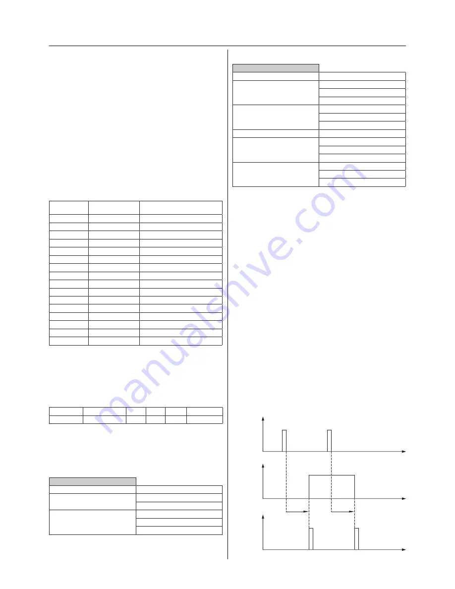
The passive status object conveys the status of the relay at
any instant (e.g. for visualisation programs which actively
read out the status).
Active feedback with a parameterised ON and OFF delay
KNX
telegram
t
t
t
Relay status
closed
1
1
0
t on
t off
0
KNX
telegram,
status feedback
open
Scenes
- Scene
The scene function of the switch actuator has an 8 bit scene
object. Using a parameter, you can define for each scene
whether the scene should be inactive, active or active with
a memory function for new actuator states. A parameter
window appears for each active scene where the settings
can be carried out. 8 independent values can be stored for
each channel. When the scene is retrieved, it can be speci-
fied that the channel switches on, switches off or does not
change its state.
A scene is activated when it receives its scene number (1
byte value starting with “1”) at the scene object. If a scene is
parameterised with a memory function, the storing of the
current channel values is carried out using the object value
of the scene (scene number) + 128 (see table).
Scene
Object value
(scene number)
Function
1
0
Retrieve scene 1
1
128
Save scene 1
2
1
Retrieve scene 2
2
129
Save scene 2
3
2
Retrieve scene 3
3
130
Save scene 3
4
3
Retrieve scene 4
4
131
Save scene 4
5
4
Retrieve scene 5
5
132
Save scene 5
6
5
Retrieve scene 6
6
133
Save scene 6
7
6
Retrieve scene 7
7
134
Save scene 7
8
7
Retrieve scene 8
8
135
Save scene 8
The scene function has likewise a low priority. Its behaviour
in combination with other functions corresponds to the
behaviour of the central function.
Communication objects
The following communication objects can be selected:
Function
Object name
Type
Prio
Flags
Behaviour
Scene
Scene object
1 byte Low
CW
Receive
Parameters
Common for all scenes: Activate the scenes.
Define for Scene 1-8:
not active / retrievable / retrievable and storable.
General scene
Parameter
Setting
Scenes are
not active
active
Scene 1-8 is
not active
retrievable
retrievable and storable


