250 Outrage
Section 4 • Electrical System
•
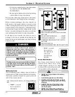
“ON”
- you will
have power to
the engin(es) as
well as all
essential boat
systems.
Battery Switches
Your 250 Outrage uses a battery selector switch to
control delivery of DC power from the two batteries.
The battery switch is located on a panel on the aft
wall of the console interior.
The battery switch has two (2) settings, OFFand
ON.
•
“OFF”
- you will
have no power to
the engines.
Batteries contain sulfuric acid which is
dangerous and can cause serious injury.
AVOID contact with skin, eyes and clothing. If
contact occurs, immediately fl ush the aff ected
area with large quantities of water and call for
medical assistance.
DANGER
The Bilge pump, stereo memory, battery charger
and clean power for the DTS system still draw
power from the house battery even if the switch
is set to “OFF”.
NOTICE
• If not using a sealed battery, check & maintain
the water level. USE DISTILLED
WATER ONLY.
• Removing the batteries from the boat during
cold weather or long term storage.
The most life shortening experience for the battery
is to be drained to zero charge before recharging.
When a battery discharges, the active material on
both positive and negative plates converts to lead
sulfate, causing the plates to become more alike in an
electrical charge. The electricity conducting battery
acid becomes weaker and the voltage drops. As the
battery remains discharged, the process continues
until recharging the battery becomes impossible.
If the battery does become run down be sure to
recharge it as soon as possible. Overcharging the
battery can be just as detrimental to its life as running
it down too far.
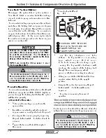
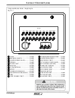
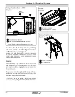
Battery Switch Panel
Fig. 4.5.1
1
2
3
4
5
6
7
BATTERY SWITCH PANEL
DUAL ENGINE BATTERY SWITCH PANEL
(OPTION)
BILGE PUMPS BREAKER ..............30AMP
WINDLASS BREAKER ....................80AMP
STARBORD ENGINE BATTERY SWITCH
(OPTION)
BATTERY SWITCH
PORT ENGINE BATTERY SWITCH (OPTION)
1
2
3
4
5
6
7
3
4
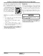
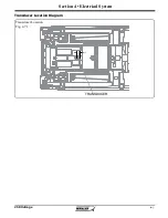
House Main Breaker
The house main breaker located
forward of the battery trays in the
console interior (see fi g. 4.1.1) must
be turned ON to provide power to all
non-essential vessel components.
• NEVER use an open fl ame in the battery
storage area.
• Avoid striking sparks near the battery.
• A battery will explode if a fl ame or spark
ignites the free hydrogen given off during
charging.
• ALWAYS disconnect the battery before
doing any work or maintenance on the
electrical system.
• NEVER turn off the battery switches or
disconnect the battery cables while the
CAUTION
Summary of Contents for 250 OUTRAGE
Page 1: ...i R 250 Outrage 250 Outrage ...
Page 2: ...ii R ...
Page 18: ...xviii î ï ð ñ ò ó ô õ ö R ø ù ú û ü ý þ ÿ ú ø ÿ ø ú ý ÿ ø ý ...
Page 42: ...1 24 Ë Ì Í Î Ï Ð Ñ Ò Ó Ô R Õ Ö Ø Ù Ú Û Ü Ý Õ Ü Ý Õ Þ Ý Ú ß ß à ß Ü á Õ â ß Ú Ý ã ...
Page 54: ...2 12 w x y z R ª ª ª ª ª ª ª ª ª µ ª º ª º µ ...
Page 72: ...2 30 µ R º À À Á À Â Ã À Ä ...
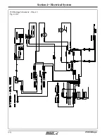
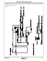
Page 111: ...250 Outrage Section 4 Electrical System 250 Outrage Schematic Sheet 1 Fig 4 9 1 ...
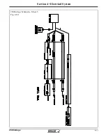
Page 112: ...250 Outrage Section 4 Electrical System 250 Outrage Schematic Sheet 2 Fig 4 10 1 ...
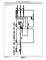
Page 113: ...250 Outrage Section 4 Electrical System 250 Outrage Schematic Sheet 3 Fig 4 11 1 ...
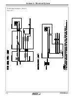
Page 114: ...250 Outrage Section 4 Electrical System 250 Outrage Schematic Sheet 4 Fig 4 12 1 ...
Page 115: ...250 Outrage Section 4 Electrical System 250 Outrage Schematic Sheet 5 Fig 4 13 1 ...
Page 116: ...250 Outrage Section 4 Electrical System 250 Outrage Schematic Sheet 6 Fig 4 14 1 ...
Page 117: ...250 Outrage Section 4 Electrical System 250 Outrage Schematic Sheet 7 Fig 4 15 1 ...
Page 118: ...250 Outrage Section 4 Electrical System 250 Outrage Schematic Sheet 8 Fig 4 16 1 ...
Page 119: ...250 Outrage Section 4 Electrical System 250 Outrage Schematic Sheet 9 Fig 4 17 1 ...
Page 120: ...250 Outrage Section 4 Electrical System 250 Outrage Schematic Sheet 10 Fig 4 18 1 ...
Page 121: ...250 Outrage Section 4 Electrical System 250 Outrage Schematic Sheet 11 Fig 4 19 1 ...
Page 122: ...250 Outrage Section 4 Electrical System 250 Outrage Schematic Sheet 12 Fig 4 20 1 ...
Page 123: ...250 Outrage Section 4 Electrical System 250 Outrage Schematic Sheet 13 Fig 4 21 1 ...
Page 124: ...250 Outrage Section 4 Electrical System 250 Outrage Schematic Sheet 14 Fig 4 22 1 ...
Page 125: ...250 Outrage Section 4 Electrical System 250 Outrage Schematic Sheet 15 Fig 4 23 1 ...
Page 126: ...250 Outrage Section 4 Electrical System 250 Outrage Schematic Sheet 16 Fig 4 24 1 ...
Page 127: ...250 Outrage Section 4 Electrical System 250 Outrage Schematic Sheet 17 Fig 4 25 1 ...
Page 128: ...250 Outrage Section 4 Electrical System 250 Outrage Schematic Sheet 18 Fig 4 26 1 ...
Page 129: ...250 Outrage Section 4 Electrical System 250 Outrage Schematic Sheet 19 Fig 4 27 1 ...
Page 130: ...250 Outrage Section 4 Electrical System 250 Outrage Schematic Sheet 20 Fig 4 28 1 ...
Page 131: ...250 Outrage Section 4 Electrical System 250 Outrage Schematic Sheet 21 Fig 4 29 1 ...
Page 132: ...250 Outrage Section 4 Electrical System THIS PAGE INTENTIONALLY LEFT BLANK ...
Page 143: ...Section 5 Care Maintenance 250 Outrage Reinforcement Location Diagram ...

