Section 5 • Care & Maintenance
250 Outrage
Long Term Storage & Winterization
Long periods of storage, winter lay-up and/or non-
use, common to boats, create unique problems. When
preparing to store a boat for extended periods of two
months or more it is best to make sure that the boat
and its systems are properly conditioned for such
extended periods of non-usage.
The guidelines presented on the following pages
give basic instructions on “winterizing” your boat
and boat systems. If inexperienced with the process
of winterization it is best to hire the services of a
professional.
In addition, always consult the owner’s manuals of
the various systems and equipment on your boat for
the manufacturer’s recommendations on winterizing
and long term storage.
Never start or run your outboard (even
momentarily) without having water circulating
through the cooling water intake holes in the
gear case. This will prevent damage to the
water pump (running dry) or overheating of
the engine.
CAUTION
Engine
Protecting your engine’s vital moving parts from
corrosion and rust caused by freezing of trapped
water or excessive condensation due to climatic
changes is very important. Freezing water in the
engine can cause extensive damage to the internal
moving parts. Internal engine parts can also be
aff ected by rust due to lack of proper lubrication
• Replace the engine oil and fi lter, running the
engine to drain out as much old oil as
possible.
• Flush the engine with fresh water using fl ush
muff s or a similar device attached to the raw
water pickup.
• Let all water drain from the engine.
Tank(s), hoses, and fuel pumps should be treated to
help prevent the formation of varnish and gum.
Temperature extremes will cause condensation to
accumulate in an empty or partially fi lled fuel tank
leading to fuel contamination and/or premature wear
of your system.
Fill the tank completely (100%) full and add
fuel stabilizer and conditioner, following the
manufacturer’s recommendations, to provide fuel
stability and corrosion protection.
Fuel System
Pay particular attention to the information
provided in “Ethanol-Blended Fuel” in section
3 of this manual.
NOTICE
• Fog the engine while it is running. Spray until
it stalls.
• Run fuel which has been treated with
conditioner and stabilizer through the
engine.
• Replace lower unit gear oil. Check for
moisture in old oil, a sign of deteriorating
seals.
• Remove the prop and grease the shaft and
threads.
• Treat all grease fi ttings with the recommended
lubricant.
• Lightly lubricate the exterior of the engine or
polish with a good wax.
• Check engine mount bolts. Ensure that they
are torqued to 55 ft/lbs.
In addition, be sure to follow all recommendations in
your engine manufacturers operation manual.
Summary of Contents for 250 OUTRAGE
Page 1: ...i R 250 Outrage 250 Outrage ...
Page 2: ...ii R ...
Page 18: ...xviii î ï ð ñ ò ó ô õ ö R ø ù ú û ü ý þ ÿ ú ø ÿ ø ú ý ÿ ø ý ...
Page 42: ...1 24 Ë Ì Í Î Ï Ð Ñ Ò Ó Ô R Õ Ö Ø Ù Ú Û Ü Ý Õ Ü Ý Õ Þ Ý Ú ß ß à ß Ü á Õ â ß Ú Ý ã ...
Page 54: ...2 12 w x y z R ª ª ª ª ª ª ª ª ª µ ª º ª º µ ...
Page 72: ...2 30 µ R º À À Á À Â Ã À Ä ...
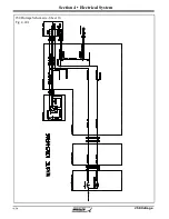
Page 111: ...250 Outrage Section 4 Electrical System 250 Outrage Schematic Sheet 1 Fig 4 9 1 ...
Page 112: ...250 Outrage Section 4 Electrical System 250 Outrage Schematic Sheet 2 Fig 4 10 1 ...
Page 113: ...250 Outrage Section 4 Electrical System 250 Outrage Schematic Sheet 3 Fig 4 11 1 ...
Page 114: ...250 Outrage Section 4 Electrical System 250 Outrage Schematic Sheet 4 Fig 4 12 1 ...
Page 115: ...250 Outrage Section 4 Electrical System 250 Outrage Schematic Sheet 5 Fig 4 13 1 ...
Page 116: ...250 Outrage Section 4 Electrical System 250 Outrage Schematic Sheet 6 Fig 4 14 1 ...
Page 117: ...250 Outrage Section 4 Electrical System 250 Outrage Schematic Sheet 7 Fig 4 15 1 ...
Page 118: ...250 Outrage Section 4 Electrical System 250 Outrage Schematic Sheet 8 Fig 4 16 1 ...
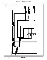
Page 119: ...250 Outrage Section 4 Electrical System 250 Outrage Schematic Sheet 9 Fig 4 17 1 ...
Page 120: ...250 Outrage Section 4 Electrical System 250 Outrage Schematic Sheet 10 Fig 4 18 1 ...
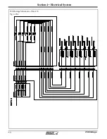
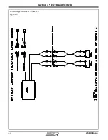
Page 121: ...250 Outrage Section 4 Electrical System 250 Outrage Schematic Sheet 11 Fig 4 19 1 ...
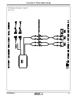
Page 122: ...250 Outrage Section 4 Electrical System 250 Outrage Schematic Sheet 12 Fig 4 20 1 ...
Page 123: ...250 Outrage Section 4 Electrical System 250 Outrage Schematic Sheet 13 Fig 4 21 1 ...
Page 124: ...250 Outrage Section 4 Electrical System 250 Outrage Schematic Sheet 14 Fig 4 22 1 ...
Page 125: ...250 Outrage Section 4 Electrical System 250 Outrage Schematic Sheet 15 Fig 4 23 1 ...
Page 126: ...250 Outrage Section 4 Electrical System 250 Outrage Schematic Sheet 16 Fig 4 24 1 ...
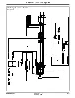
Page 127: ...250 Outrage Section 4 Electrical System 250 Outrage Schematic Sheet 17 Fig 4 25 1 ...
Page 128: ...250 Outrage Section 4 Electrical System 250 Outrage Schematic Sheet 18 Fig 4 26 1 ...
Page 129: ...250 Outrage Section 4 Electrical System 250 Outrage Schematic Sheet 19 Fig 4 27 1 ...
Page 130: ...250 Outrage Section 4 Electrical System 250 Outrage Schematic Sheet 20 Fig 4 28 1 ...
Page 131: ...250 Outrage Section 4 Electrical System 250 Outrage Schematic Sheet 21 Fig 4 29 1 ...
Page 132: ...250 Outrage Section 4 Electrical System THIS PAGE INTENTIONALLY LEFT BLANK ...
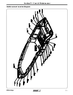
Page 143: ...Section 5 Care Maintenance 250 Outrage Reinforcement Location Diagram ...

