250 Outrage
Section 4 • Electrical System
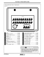
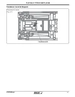
Component Breaker Panel - Single Engine
Fig. 4.3.1
1
HORN ..............................................10 AMP
NAV/ANCH LIGHTS ........................10 AMP
COURTESY/MAP LIGHTS .............10 AMP
STEREO ..........................................15 AMP
FLOOD LIGHT ................................10 AMP
TRIM TAB ........................................20 AMP
12V RECEPTACLE .........................15 AMP
WIPER .............................................10 AMP
CONSOLE FUSE BLOCK ..............40 AMP
ELECTRONICS FUSE BLOCK ......40 AMP
VENT .............................................. 10 AMP
PORT FISHBOX PUMP ..................10 AMP
2
3
4
5
6
7
8
9
10
11
12
13
14
15
16
17
18
19
20
21
22
23
STARBOARD FISHBOX PUMP .....10 AMP
FRESH WATER PUMP ...................15 AMP
RAW WATER PUMP .......................15 AMP
L/P LIVEWELL PUMP/LIGHTS ........6 AMP
AFT LIVEWELL (OPTION) ...............6 AMP
WINDLASS CONTROL ..................10 AMP
VACUFLUSH PUMP .........................5 AMP
DISCHARGE PUMP .......................20 AMP
IGNITION SWITCH
FWD BILGE PUMP ...........................5 AMP
AFT BILGE PUMP ............................6 AMP
AUX BILGE PUMP ............................6 AMP
1
2
3
4
5
6
7
8
9
10
11
12 13 14 15 16 17 18
19 20
21
22
23
NEVER reset a breaker without fi rst determining
and correcting the cause of the trip. Should a circuit
breaker repeatedly trip, have a qualifi ed electrician
determine and correct the cause.
CAUTION
24
24
Summary of Contents for 250 OUTRAGE
Page 1: ...i R 250 Outrage 250 Outrage ...
Page 2: ...ii R ...
Page 18: ...xviii î ï ð ñ ò ó ô õ ö R ø ù ú û ü ý þ ÿ ú ø ÿ ø ú ý ÿ ø ý ...
Page 42: ...1 24 Ë Ì Í Î Ï Ð Ñ Ò Ó Ô R Õ Ö Ø Ù Ú Û Ü Ý Õ Ü Ý Õ Þ Ý Ú ß ß à ß Ü á Õ â ß Ú Ý ã ...
Page 54: ...2 12 w x y z R ª ª ª ª ª ª ª ª ª µ ª º ª º µ ...
Page 72: ...2 30 µ R º À À Á À Â Ã À Ä ...
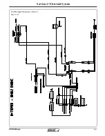
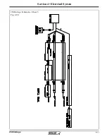
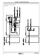
Page 111: ...250 Outrage Section 4 Electrical System 250 Outrage Schematic Sheet 1 Fig 4 9 1 ...
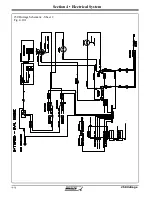
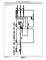
Page 112: ...250 Outrage Section 4 Electrical System 250 Outrage Schematic Sheet 2 Fig 4 10 1 ...
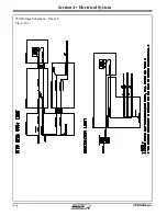
Page 113: ...250 Outrage Section 4 Electrical System 250 Outrage Schematic Sheet 3 Fig 4 11 1 ...
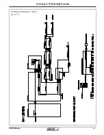
Page 114: ...250 Outrage Section 4 Electrical System 250 Outrage Schematic Sheet 4 Fig 4 12 1 ...
Page 115: ...250 Outrage Section 4 Electrical System 250 Outrage Schematic Sheet 5 Fig 4 13 1 ...
Page 116: ...250 Outrage Section 4 Electrical System 250 Outrage Schematic Sheet 6 Fig 4 14 1 ...
Page 117: ...250 Outrage Section 4 Electrical System 250 Outrage Schematic Sheet 7 Fig 4 15 1 ...
Page 118: ...250 Outrage Section 4 Electrical System 250 Outrage Schematic Sheet 8 Fig 4 16 1 ...
Page 119: ...250 Outrage Section 4 Electrical System 250 Outrage Schematic Sheet 9 Fig 4 17 1 ...
Page 120: ...250 Outrage Section 4 Electrical System 250 Outrage Schematic Sheet 10 Fig 4 18 1 ...
Page 121: ...250 Outrage Section 4 Electrical System 250 Outrage Schematic Sheet 11 Fig 4 19 1 ...
Page 122: ...250 Outrage Section 4 Electrical System 250 Outrage Schematic Sheet 12 Fig 4 20 1 ...
Page 123: ...250 Outrage Section 4 Electrical System 250 Outrage Schematic Sheet 13 Fig 4 21 1 ...
Page 124: ...250 Outrage Section 4 Electrical System 250 Outrage Schematic Sheet 14 Fig 4 22 1 ...
Page 125: ...250 Outrage Section 4 Electrical System 250 Outrage Schematic Sheet 15 Fig 4 23 1 ...
Page 126: ...250 Outrage Section 4 Electrical System 250 Outrage Schematic Sheet 16 Fig 4 24 1 ...
Page 127: ...250 Outrage Section 4 Electrical System 250 Outrage Schematic Sheet 17 Fig 4 25 1 ...
Page 128: ...250 Outrage Section 4 Electrical System 250 Outrage Schematic Sheet 18 Fig 4 26 1 ...
Page 129: ...250 Outrage Section 4 Electrical System 250 Outrage Schematic Sheet 19 Fig 4 27 1 ...
Page 130: ...250 Outrage Section 4 Electrical System 250 Outrage Schematic Sheet 20 Fig 4 28 1 ...
Page 131: ...250 Outrage Section 4 Electrical System 250 Outrage Schematic Sheet 21 Fig 4 29 1 ...
Page 132: ...250 Outrage Section 4 Electrical System THIS PAGE INTENTIONALLY LEFT BLANK ...
Page 143: ...Section 5 Care Maintenance 250 Outrage Reinforcement Location Diagram ...

