


13
•
OPERATION INSTRUCTIONS
1.
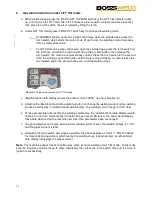
The starting up display
Switch on the welding power source, the front panel displays as Chart 1. After the (Multifunctional
data display) (or any key or knob on front panel) flashes for 5 seconds, the machine enters into the
welding mode that saved in the last shutdown.
Chart 1:
The starting-up display interface.
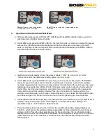
2.
Operation instruction under STICK mode
a.
When welding stops, Press the (STICK/LIFT TIG/MIG switch key), the STICK indicator lights up,
and it turns into STICK mode.
b.
When under STICK mode, pressing the (VRD/2T/4T switch key), VRD function is enabled when
the indicator lights up, and displays in (multifunctional data display). Or, the VRD function isn’t
enabled if the indicator is off.
c.
(Multifunctional data display) shows the preset current“080A”, its unit is ampere (A).
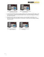
d.
Adjusting the (Multifunctional data adjusting knob) can change the welding current during
welding process, and displayed in (multifunctional data display). The welding current range is
10A-75A.
e.
Three seconds later after setting the welding parameters, the (multifunctional data display)
would flash for one time, which means the data has been saved. Moreover, the panel will
display this data when you restart the machine
.
f.
The panel displays as Chart 4. when perform welding, which means the welding voltage is
23.2V, and the preset current 80A. 5 seconds later, it returns to the preset current state.
Chart 4
: The display status when welding under STICK mode.
Summary of Contents for TREO 175
Page 1: ...User Manual TREO 175 ...
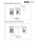
Page 11: ...11 Explanatory drawing for installation of TREO 175 STICK ...
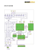
Page 22: ...22 CIRCUIT DIAGRAM ...
Page 30: ...30 Notes ...
Page 31: ...31 Notes ...


