background image

BOSS6000 | BOSS8000

s i s t e m i   d i   f i s s a g g i o

®

w w w . b o s s o n g . c o m

10

IT

EN

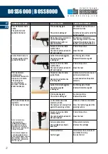
FISSAGGIO

A causa delle diverse resistenze e durezze 

superficiali del calcestruzzo e delle diverse tipologie 

e spessori di acciaio, il fissaggio su questi materiali 

richiederà l’utilizzo di diverse potenze di sparo. 

Usando l’apparecchio l’operatore ha la possibilità 

di regolare la potenza dello sparo tramite la 

rotella di regolazione di potenza posta sul lato 

della chiodatrice a seconda del tipo di fissaggio 

da eseguire. La corretta potenza di sparo è dettata 

dall’esperienza e necessita di un numero di colpi di 

prova per essere regolata. Il primo sparo di prova 

dovrà essere eseguito con la potenza minima per 

poi essere incrementata fino alla potenza che 

soddisfi il grado di penetrazione desiderato.

MINIMO INTERASSE: I chiodi non dovranno essere 

fissati ad una distanza inferiore agli 80 mm l’uno 

con l’altro in calcestruzzo. Quando il fissaggio viene 

eseguito su acciaio rispettare un interasse minimo 

di almeno 20 mm.

MINIMA DISTANZA DAL BORDO: Quando i chiodi 

sono inseriti in calcestruzzo mantenere una 

distanza di almeno 80 mm. Quando i chiodi 

vengono sparati in elementi di acciaio mantenere 

una distanza dal bordo di almeno 20 mm.

SPESSORE MINIMO DEL MATERIALE BASE: Per il 

fissaggio in materiale base calcestruzzo min. 80 

mm, per il fissaggio in acciaio min. 5 mm.

NON ESEGUIRE IL FISSAGGIO IN ACCIAI CON 

SPESSORE INFERIORE AL DIAMETRO DEL GAMBO 

DEL CHIODO.

Il fissaggio dovrà essere sempre visibile dopo lo 

sparo.

È tassativamente vietato usare l’apparecchio 

per eseguire fissaggi di tegole, mattoni forati, 

ceramica, granito, vetro, elementi in acciaio con 

elevata durezza superficiale.

NON ESEGUIRE MAI FISSAGGI IN MATERIALI 

FORATI. NON ESEGUIRE FISSAGGI ATTRAVERSO 

SALDATURE DI SUPERIFICI.

LA CANNA DELL’APPARECCHIO DOVRÀ ESSERE 

SEMPRE PERPENDICOLARE ALLA SUPERIFICE DI 

LAVORO.

NON SPARARE MAI SENZA CHIODI, POTREBBE 

CAUSARE DANNEGGIAMENTI ALL’ATTREZZO.

NON SPARARE MAI IN FORI.

FASTENING

Because of differences in hardness of concrete and 

thickness of steel, fastenings to these materials 

requires different strength of power.

Using the tool you have the possibility of regulate 

the power by turning the hand wheel until the 

resistance of required power is reached.

The proper power selection is the matter of 

experience and needs a number of trial fastenings. 

The first test should be made with the lowest 

power, and then power should be increased until 

desired penetration is reached.

MINIMUM CENTRE DISTANCE: nails should be fixed 

with a distance not less than 80 mm the one 

from the other in concrete. For fixing on steel the 

minimum distance should be at least of 20 mm.

MINIMUM EDGE DISTANCE: When nails are fixed 

into concrete keep a distance of at least 80 mm. 

When nails are shot into steel keep an edge distance 

of at least 20 mm.

MINIMUM THICKNESS OF THE BASE MATERIAL: For 

fixings into concrete min. 80 mm, for fixings into 

steel min 5 mm.

DO NOT FASTEN INTO STEEL THINNER THAN THE 

FASTENER SHANK DIAMETER.

The fixing will be visible after the shoot.

To eliminate spalling and during work with the 

single shoot version, a Spall Shield should be used.

You should not use your tool to do fastenings into 

roof tiles, hollow bricks, glazing bricks, surface-

hardened steel. It is forbidden to use the tool for 

fixing fragile material, even if is hard, such as cast 

iron, hardened steel, marble, granite, glass, ceramic 

material, drilled bricks, etc.

NEVER DO FASTENINGS INTO PERFORATED OR 

BRITTLED MATERIAL. NEVER DO FASTENINGS INTO 

WELDED SURFACES.

ALWAYS POINT THE TOOL PERPENDICULAR TO 

THE WORK SURFACE.

NEVER FIRE THE TOOL WITHOUT FASTENER - IT 

MAY DAMAGE THE TOOL.

NEVER FIRE INTO A HOLE.

Summary of Contents for BOSS6000

Page 1: ...BOSS6000 BOSS8000 s i s t e m i d i f i s s a g g i o w w w b o s s o n g c o m manuale d uso operator s manual ...

Page 2: ...uire le istruzioni di sicurezza contenute in questo manuale unitamente a quelle verbali date dal servizio di assistenza tecnica autorizzato è una VOSTRA RESPONSABILITÀ READ CAREFULLY THE INSTRUCTIONS CONTAINED IN THIS GUIDE BEFORE USING THE TOOLS BOSSONG S p A tools must be used by adult expert personnel only who knows well how to realize the work as well as the safety rules operational and mainte...

Page 3: ...E E PULIZIA MAINTENANCE CLEANING 14 CONVERSIONE DA SPARO SINGOLO A CARICATORE CONVERSION IN MAGAZINE VERSION 18 RISOLUZIONE PROBLEMI DURANTE L UTILIZZO DEL DISPOSITIVO TROUBLESHOOTING TIPS WHEN USING THE BOLT SET DEVICE 20 CONTENUTO DELLA CONFEZIONE KIT CONTENTS 23 ESPLOSO E PARTI DI RICAMBIO BOSS 6000 BOSS 8000 SCHEMATIC SPARE PARTS BOSS 6000 BOSS 8000 24 ESPLOSO E PARTI DI RICAMBIO BOSS 6000 M35...

Page 4: ...oibito puntare l attrezzo verso persone e o animali 10 Durante le operazioni di sparo con colpo singolo si raccomanda di usare l attrezzo con la prote zione frontale montata sull apparecchio MAIN OPERATING AND SAFETY INSTRUCTIONS 1 Before using the tool make sure there are no cartridges left inside When your work is finished unload the possible cartridges and nails 2 Before to use the tool indicat...

Page 5: ... con cura l attrez zo nella sua confezione originale così come le cariche Utilizzare per il trasporto sempre la confezione originale 14 Solo componenti originali BOSSONG S p A dovranno essere utilizzati per sostituire parti dell apparecchio 15 Durante le operazioni di sparo indossare prote zioni adeguate 12 In case of malfunction of the tool please ensure it immediately out of service Please read ...

Page 6: ...forzate durante il caricamento o inserite usando altri attrezzi 2 Only use the following types of color coded cartridges caliber 6 8 11 green min strength yellow medium strength red max strength Cartridges should be protected from heat and humidity during storage Insert the cartridges into the tool through the slot below the handle and push until they are completely inside You should see the plast...

Page 7: ... loaded the tool is ready to shoot Place the muzzle of the fastening tool against the work surface at a right angle perpendicularly to the work surface Keep it balanced The worker should position himself behind the tool in range with the axis of the tool guide The assistance personnel should be behind the worker Push the tool completely against the surface and pull the trigger Please shoot only if...

Page 8: ... caricato solo da personale addetto all uso Le cartucce non devono essere forzate durante il caricamento o inserite usando altri attrezzi 2 Only use the following types of color coded cartridges caliber 6 8 11 green min strength yellow medium strength red max strength Cartridges should be protected from heat and humidity during storage Insert the cartridges into the tool through the slot below the...

Page 9: ...ing tool against the work surface at a right angle perpendicularly to the work surface Keep it balanced The worker should position himself behind the tool in range with the axis of the tool guide The assistance personnel should be behind the worker Push the tool completely against the surface and pull the trigger Please shoot only if no one is in a dangerous position around or inside the working a...

Page 10: ...ON ESEGUIRE FISSAGGI ATTRAVERSO SALDATURE DI SUPERIFICI LA CANNA DELL APPARECCHIO DOVRÀ ESSERE SEMPRE PERPENDICOLARE ALLA SUPERIFICE DI LAVORO NON SPARARE MAI SENZA CHIODI POTREBBE CAUSARE DANNEGGIAMENTI ALL ATTREZZO NON SPARARE MAI IN FORI FASTENING Because of differences in hardness of concrete and thickness of steel fastenings to these materials requires different strength of power Using the to...

Page 11: ...issaggio acciaio acciaio Fixing steel steel Cmin 15 20mm Smin 20 mm hef 14mm 2 mm tII min 5 mm S235 S355 hst 2 3 mm tI S235 S355 se tI 4 0 necessario preforo ø 4 5 mm if tI 4 0 pre drilled ø 4 5 mm is mandatory tI tII 10 mm 80 80 80 80 80 80 80 80 80 80 60 30 30 80 80 80 80 60 30 30 APPLICAZIONI PRINCIPALI Prima di sparare il colpo è necessario assicurarsi che le superfici siano piane stabili e pe...

Page 12: ... too low Aumentare la potenza dello sparo o passare a cartucce più potenti Increase fire power or switch to more powerful cartridges Acciaio troppo resistente Steel is too hard Utilizzare chiodi di qualità diversa Use higher resistance nails Rottura del chiodo The nail breaks Chiodo troppo lungo Tail is too long Utilizzare chiodi più corti Use shorter nail Acciaio troppo resistente Steel is too ha...

Page 13: ...o la superficie di calcestruzzo Reinforcement under the surface Cambiare posizione Change position Lo strumento non è stato posizionato perpendicolarmente alla superficie di lavoro The tool is not placed perpendicular to the working surface Utilizzare lo strumento perpendicolarmente alla superficie di lavoro Use the tool perpendicular to the working surface Sfaldamento del calcestruzzo Concrete sp...

Page 14: ...000 spari L apparecchio dovrà essere controllato pulito ed oliato alla fine della giornata di lavoro e dovrà essere spedito almeno una volta all anno al produttore o a un tecnico autorizzato per una revisione generale Non sparare più di 200 colpi all ora per garantire sicurezza di funzionamento ed un ottima durabilità del pistone Un attrezzo pulito e mantenuto nel modo corretto garantisce migliori...

Page 15: ...Controllare visivamente l anello del pistone se danneggiato sostituirlo 8 Check visually the piston disk if it is damaged replace it 9 Controllare visivamente il pistone soprattutto sulla punta e sulla parte posteriore se danneggiato sostituirlo 9 Check visually the piston especially on the tip and on the bottom part if it is damaged replace it 10 Pulire il pistone con la spazzola in ferro da spor...

Page 16: ... Controllare visivamente la canna Se danneggiata sostituirla Pulire la canna con l apposito scovolino in metallo da sporcizia e dai residui presenti Oliare e successivamente rimuovere con un panno asciutto l eccesso di olio residuo 13 Check visually the barrel if it is damaged replace it Clean the barrel with the steel brush to remove dirt and residues Oil the guide and then remove with a dry clot...

Page 17: ...oni correttamente sparando nelle massime condizioni di sicurezza 19 Once the assembly is done check the right working of the tool shooting in the maximum safe conditions Per la versione con caricatore l assieme bussola punti 2 11 12 17 18 è sostituito dal caricatore Le operazioni di manutenzione e pulizia sono le stesse della versione a colpo singolo Per la versione con caricatore utilizzare appos...

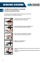
Page 18: ...mmortizzatore dalla canna 3 Eject the piston and the returner from the barrel 4 Mantenere il corpo dell attrezzo 4 Keep the tool of the body 5 Separare l ammortizzatore dal pistone Separare l anello del pistone dal pistone 5 Separate the rubber returner from the piston Separate the piston ring from the piston CONVERSIONE DA SPARO SINGOLO A CARICATORE CONVERSION IN MAGAZINE VERSION Prima di procede...

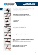
Page 19: ...zzatore 7 Put on the proper piston the piston disk and the rubber return 8 Prendere il caricatore 8 Take the magazine 9 Inserire il pistone completo all interno della canna 9 Insert the complete piston inside of the barrel 10 Prendere il caricatore ed allinearlo all attrezzo 10 Keep the magazine in line with the tool body 11 Installare il caricatore al corpo dell attrezzo utilizzando il meccanismo...

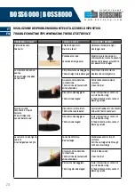
Page 20: ...tivo al centro di assistenza Bossong If the problem persists contact Bossong service Non è possibile rimuovere lo strip di cartucce The cartridge strip cannot be removed Dispositivo surriscaldato The tool has overheated Lasciar raffreddare lo strumento Allow the tool to cool down Dispositivo danneggiato The tool is damaged Invia il dispositivo al centro di assistenza Bossong If the problem persist...

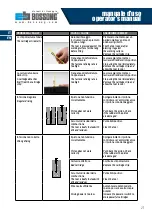
Page 21: ...ddare il dispositivo Stop using the tool immediately Remove the cartridge strip and allow the tool to cool Infissione irregolare Irregular driving Il pistone non funziona correttamente Piston does not work correctly Spingere indietro il pistone controllare se l ammortizzatore o il pistone sono danneggiati Push back the piston Check if the rubber or the piston are damaged Accumulo di residui della ...

Page 22: ...aterial fastener is driven too deeply Chiodo non inserito nella guida chiodo Nails not inserted into the fastener guide Allentare ed estrarre con cura il pistone dal materiale Loosen and extract the piston carefully Guida chiodo danneggiata The Fastener guide is damaged Sostituire guida chiodo Replace the fastener guide Pistone danneggiato The piston is damaged Sostituire pistone Replace the pisto...

Page 23: ...8 1 7 6 5 4 2 3 1 Chiodatrice a colpo singolo Powder actuated tool 2 Chiave a brugola Hex wrench 3 Paraschegge Spall guard 4 Kit pulizia spazzole e olio Cleaning kit brush and lubricant 5 Ammortizzatori di ricambio Rubber return as spare part 6 Kit sicurezza tappi occhiali e guanti Safety kit ear protection eye protection and protective gloves 7 Caricatore opzionale solo su richiesta Magazine opti...

Page 24: ...R BOLT 065000 17 18 OTTURATORE FIRING PIN MECH 065000 18 19 ASTINA OTTURATORE PUSHING PIN 065000 19 20 NOTTOLINO FIRING PIN SEAR 065000 20 21 MOLLA NOTTOLINO FIRING PIN SEAR SPRING 065000 21 22 PERCUSSORE FIRING PIN COMPLETE 065000 22 23 MOLLA OTTURATORE MECH SPRING 065000 23 24 MOLLA PERCUSSORE FIRING PIN SPRING 065000 24 25 BASE MANICOTTO RECEIVER BASE 065000 25 26 VITE PER LEVA DI AVANAZAMENTO ...

Page 25: ...manuale d uso operator s manual s i s t e m i d i f i s s a g g i o w w w b o s s o n g c o m 25 24 16 15 14 20 18 22 23 21 19 33 2 17 35 34 6 4 38 5 36 8 3 7 10 9 1 13 12 11 39 ...

Page 26: ...ORE REGULATOR NUT 065000 16 17 VITE REGOLATORE REGULATOR BOLT 065000 17 18 OTTURATORE FIRING PIN MECH 065000 18 19 ASTINA OTTURATORE PUSHING PIN 065000 19 20 NOTTOLINO FIRING PIN SEAR 065000 20 21 MOLLA NOTTOLINO FIRING PIN SEAR SPRING 065000 21 22 PERCUSSORE FIRING PIN COMPLETE 065000 22 23 MOLLA OTTURATORE MECH SPRING 065000 23 24 MOLLA PERCUSSORE FIRING PIN SPRING 065000 24 25 BASE MANICOTTO RE...

Page 27: ...manuale d uso operator s manual s i s t e m i d i f i s s a g g i o w w w b o s s o n g c o m 27 CARICATORE COMPLETO COMPLETE MAGAZINE ...

Page 28: ...to con pistone Indirect with piston Valori di rumorosità Values of noise ANNEX D EN 15895 1 cal 6 8 11mm RED Livello di pressione sonora sul posto di lavoro Emission sound pressure level at work station LpA 1s 108 3 dB A Livello di picco della pressione sonora Peak emission sound pressure level LpC peak 140 3 dB C Livello di potenza sonora Noise power level LWA 1s 115 3 dB A Vibrazioni Vibration I...

Page 29: ...Indiretto con pistone Indirect with piston Valori di rumorosità Values of noise ANNEX D EN 15895 1 cal 6 8 11mm RED Livello di pressione sonora sul posto di lavoro Emission sound pressure level at work station LpA 1s 108 3 dB A Livello di picco della pressione sonora Peak emission sound pressure level LpC peak 140 3 dB C Livello di potenza sonora Noise power level LWA 1s 115 3 dB A Vibrazioni Vibr...

Page 30: ... Materiale base ACCIAIO Base material STEEL KDHM20 KDH20 KD20 GD8 1514 GD6 820 Lmax lunghezza totale del chiodo total length of the nails codice code Descrizione Description 065000 50 CARICATORE CORTO M35 SHORT MAGAZINE M35 067000 50 CARICATORE LUNGO M75 LONG MAGAZINE M75 065000 6 BUSSOLA CORTA SHORT BASESPLATE 067000 6 BUSSOLA LUNGA LONG BASESPLATE 065000 39 PARASCHEGGE SPALL GUARD 065000 5 GUIDA...

Page 31: ...are parts must be used in the tool 4 This warranty provides the replacement of defective parts only Parts requiring repair or replacement as a result of normal wear and tear are not covered by this warranty 5 Warranty do not cover neither costs to repair the tool neither transport freight 6 BOSSONG S p A is not obliged for damages losses or expenses in connection with the use or inability to use t...

Page 32: ...s i s t e m i d i f i s s a g g i o BOSSONG S p A Sede Head Quarter Via E Fermi 49 51 Z I 2 24050 GRASSOBBIO Bergamo Italy Tel 39 035 3846 011 Fax 39 035 3846 012 info bossong com www bossong com ...

Reviews: