background image

60

309743

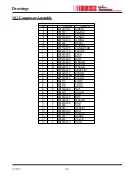
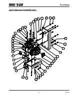
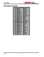
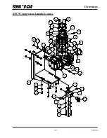
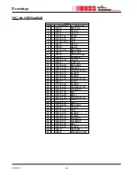
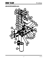
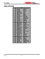
10G Air Oil Manifold

Drawings

Parts List

ITEM

QTY

PART NUMBER

DESCRIPTION

1

1 301421

SWITCH

2

1 300057 VALVE

3

1 301827

VALVE

4

1 993504-141

PLUG

5

1 961902-012

TEE

6

1 977704-0404

TEE

7

1 304121

HEAD

8

1 300599

HEAD

9

1 907603-010

BUSHING

10

1 304814 BRACKET

11

1 304122

COALESCER

12

1 300005

ELEMENT

13

1 300022-075

VALVE

14

1 300605

ORIFICE

15

1 907604-030

BUSHING

16

2 960412-075

NIPPLE

17

1 960112-075

CONNECTOR

18

1 987302-012

ELBOW

19

1 987305-025 

ELBOW

20

1 988204-025

CONNECTOR

21

1 304210

TUBE

22

1 977604-025 ELBOW

23

1 987204-025

CONNECTOR

24

4 938206-071

WASHER

25

2 925506-198

NUT

26

2 929704-050

BOLT

27

1 960120-125

CONNECTOR

28

1 961912-075 TEE

29

2 929806-150

BOLT

30

1 907600-005

BUSHING

31

1 307855

VALVE

32

1 961712-075

TEE

33

1 960212-075

ELBOW

34

1 987305-012

ELBOW

35

2 938808-200

WASHER

36

2 938605-071

WASHER

37

2 929208-200

BOLT

38

1 993302-025

ELBOW

39

1 309470

SENDER

40

1 309484

TRANSDUCER

Summary of Contents for 8060 UBI

Page 1: ... in a safe and convenient location for future reference For technical support Phone 800 635 6587 USA Phone 219 324 7776 Outside USA Fax 877 254 4249 USA service bossair com email http www bossair com website 309743 KWB 11 13 2014 Operator Manual BOSS 8060 UBI PTO Air Compressor This manual is foroperatorand maintenance personnel only ...

Page 2: ...309743 ...

Page 3: ...eral Overview 20 Inspection Prior to Moving Vehicle 20 21 Job Site Considerations 21 Starting the Compressor System 21 Stopping the Compressor System 22 OperatingMultipleComponents ifequipped 22 Checking theAir Filter 22 Shutdowns 23 Compressor Lockout 23 System Safeties 24 25 B CAN 27 32 B CAN Overview 28 B CAN Basic Display 28 29 Compressor Pressure Gauge 28 CompressorTemperature Gauge 28 Hour M...

Page 4: ...ty ReturnGoodsInstructions 42 WarrantyClaims PreparationofPartReturn 42 ReturnorWarrantyClaims FilingProcedures 42 General 43 Damage inTransit 43 ScrewCompressorAirendExchangeProgram 44 Drawings 45 69 10G CompressorAssembly 46 47 RSC9 CompressorAssembly 48 49 14D CompressorAssembly 50 51 10G RSC9 SumpTankAssembly 52 53 14D Sump TankAssembly 54 55 B CANAssembly 56 57 Air FilterAssembly 58 59 10GAir...

Page 5: ...5 309743 Safety Safety ...

Page 6: ...oss Industries Inc expressly disclaims responsibility or liability for any injury or damage caused by the failure to observe the following specified precautions or by failure to exercise the ordinary caution and due care required when operating or handling the Boss Industries Inc 8060 UBI PTO compressor system even though not expressly specified Indicates a practice which if not avoided could resu...

Page 7: ...le override or remove system safeties or controls eithertemporarilyorpermanently Overriding safetieswillresultinseriousinjury death and ordamageto equipment Fullyreadandunderstandthismanualandallother associateddocumentsbeforeinstalling operating maintaining and orservicingthisequipment Failureto complycouldresultinpersonalinjuryordeathand or damage to equipment and property The Boss 8060 UBI PTO ...

Page 8: ... compres sorsystemcontainssmallparticlesofoilthatmustnotbe ingested Thiswillresultinseriousinjury death and or damagetoequipment Never adjust the pressure regulator to increase the system pressure above 125 PSIG If pressure require ments are higher contact Boss Industries Inc for necessary component changes Failure to comply could result in personal injury or death and or damage to equipmentandpro...

Page 9: ...ervicing a Boss 8060 UBI PTO compressorsystem Failure to comply could result in personal injury or death and or damage to equipment and property The Boss 8060 UBI PTO compressor system contains ASME certified pressure vessels Never attempt to repair or modify any pressure vessel Failure to comply could result in personal injury or death and or damage to equipmentandproperty Do not attempt to servi...

Page 10: ...the compressor package Failure to comply could result in personal injury or death and or damage to equipment and property Readtheoperatorsmanualbeforestartingthisunit Failure to adhere to instructions can result in severe personalinjury Replacementmanualscanbepurchased fromBossIndustries Inc The B CAN is not a touch screen unit To operate use the buttons below the screen SafetyWarnings cont Operat...

Page 11: ...ateflowofcoolingairforitscontinuedoperation Never operate the unit inside any room or enclosure where thefreeflowofcoolingairintoandoutoftheunitmightbe obstructed Withoutsufficientcoolingairflow thecom pressorquicklyoverheats damagingtheunitandnearby property Maximum compressor capacity may be reduced where ambient temperatures exceed 100 F Do not pressure wash or apply excessive force to the face...

Page 12: ...12 309743 Safety ...

Page 13: ...13 309743 Welcome Welcome ...

Page 14: ...e processes Hydrauliccalculationsinclude85 mechanicalefficiencyand96 volumetricefficiency Specificationssubjecttochangewithoutpriornotice G I S P 0 1 1 y r e v i l e D M F C 0 6 5 8 0 0 1 5 2 1 0 6 1 5 8 1 1 5 0 3 r o s s e r p m o C o t M P R d e e p S t u p n I M P R 0 5 7 0 1 0 1 0 0 2 1 0 5 4 1 5 7 8 1 0 6 1 2 I B H U 0 6 0 8 r o f I S P 0 0 2 2 M P G t u p n I M P G 2 5 1 5 0 2 4 4 2 4 9 2 0 ...

Page 15: ...15 309743 Description of Components Description of Components ...

Page 16: ...tinuous air compressor operation The tank safety relief valve is located at the top of the sump tank This valve acts as a backup to protect the system from excessive pressure buildup as a result of a system malfunction Also in the tank assembly is the oil fill cap and oil level sightglass Compressor Assembly The heart of the Boss 8060 UBI PTO air compressor system is the rotary screw airend The ro...

Page 17: ...m is shut off This valve is piloted by a signal from the intake valve and vents the system pressure to atmosphere The most overlooked component in the Boss 8060 UBI PTO compressor system is the minimum pressure orifice This orifice is designed to maintain adequate pressure in the system to ensure proper oil circulation Air Oil Manifold The air oil manifold is a common point for senders and switche...

Page 18: ...oss 8060 UBI PTO compressor system Air is drawn through this assembly and into the intake valve on the compressor assembly The air filter assembly is a two stage system that is capable of handling medium to high dust environ ments The system incorporates an acoustical rain cap and corrosion resistant housing The air filter assembly also includes a service indicator that shows the life of the filte...

Page 19: ...19 309743 Operation Operation ...

Page 20: ...sure to follow all company policies and procedures Operation of the compressor is controlled with the first button on the B CAN The color and text of the button changes with the current state of operation The possible states are If the system has a generator GEN or hydraulic pump HYD installed the 5th button will be used to control it Engagement is the same as for the compressor A green ENGAGE COM...

Page 21: ...e the reasons why the compressor is not ready to engage NOTE If vehicle is a Ford SuperDuty a green button does not always mean compressor is ready to engage Additional safety checks will be done when attempting to engage the compressor 5 Press the green ENGAGE COMPR button to start the compressor 6 Verify engine speed elevates and compressor reaches normal operating pressure 7 Service valves can ...

Page 22: ...it can be run separately from the compressor Follow on screen instructions for starting ancillary equipment controlled by the B CAN Checking theAirFilter Because the life of the Air Filter is dependent on the operating environment the B CAN requires the operator to visually inspect the air filter service indicator After every 25 hours of compressor operation the B CAN will prompt you to check the ...

Page 23: ...s intended to provide some flexibility in wrapping up current compressor functions until a replacement compressor arrives The compressor should not be re engaged until the cause of the shutdown has been determined and fixed Compressor Lockout If any combination of three shutdowns occur within one hour of compressor operation the compressor will lock and must be taken in for service before operatio...

Page 24: ...r o r r E h c t i w S e r u s s e r P O T P t i u c r i C y t e f a S d r o F h c t i w s e r u s s e r p O T P e h t r o t n e s n o c d n e s t o n d i d t i u c r i C y t e f a S d r o F e h T e c i v r e s r o f n i e k a t s t s i s r e p s i h t f i d n a y r t e R d e v i e c e r t o n s a w k c a b d e e f e r u s s e r P g n i d l i u B t o N r p m o C e r u s n E e r u s s e r p g n i d ...

Page 25: ...e v o b A M P R d y H y l s u o e n a t l u m i s n u r e b t o n n a c p m u p c i l u a r d y h d n a r o s s e r p m o c e h T M P R r p m o C n i M w o l e B M P R d y H y l s u o e n a t l u m i s n u r e b t o n n a c p m u p c i l u a r d y h d n a r o s s e r p m o c e h T n e G e r o f e B r p m o C e g a g n E t s u M r o t a r e n e g e h t e r o f e b d e g a g n e e b t s u m r o s s ...

Page 26: ...26 309743 Operation ...

Page 27: ...27 309743 B CAN B CAN ...

Page 28: ...e bottom as shown in the figure below Compressor Pressure Gauge The Compressor Pressure Gauge indicates the current air pressure in the system This gauge is color coded to alert operators if the pressure is outside of the designed range The gauge should be in the green area during normal operation If the reading is in the yellow area the system pressure is outside of the expected range Should the ...

Page 29: ...abels The button labels show the current function of each of the five buttons The possible functions for each of the buttons are listed below Button 1 This button will always attempt to toggle the state of the compressor Button 2 This button label will be blank Button 3 This button will flash an orange triangle with an exclamation point inside whenever there are active warnings Pressing the button...

Page 30: ...hile the compressor is running Ensure the system is turned off prior to proceeding To enter the menu press and release the MENU button Information Screen If Information is selected from the main menu this will display the System Information tab This screen will display the following Boss Serial Number This is used for quick access to the serial number Last ServiceAccess By This will tell you who w...

Page 31: ...ions are 5 Sec 15 Sec default 1 Min and OFF Service Menu The Service Menu selection will take you to a new menu that allows you to view shutdowns and faults Shutdowns are recorded for high compressor temperature and high compressor pressure Faults are recorded for invalid temperature and pressure connections Here you will be able to view active shutdowns and faults and a summary of incidents for b...

Page 32: ... fixed Fault Summary The fault summary will list the total count of each type of fault Afault will only register in the summary if the compressor system was running when the fault occurred Switch to Service Mode This is where trained service personnel will sign in to perform maintenance and view additional service information Pressing the BACK button will return to the previous screen ...

Page 33: ...33 309743 Maintenance Maintenance ...

Page 34: ... area contact Boss Industries Inc Phone 800 635 6587 USA Phone 219 324 7776 Outside USA LocalFax 877 254 4249 service bossair com email http www bossair com website Compressor must be shutdown and completely relieved of pressure prior to checkingfluidlevels Openservicevalvetoensurereliefofsystemairpres sure Relieve all stored air pressure energy prior to starting machine Failure tocomplywiththiswa...

Page 35: ... k a e l r o f l a e s t f a h s r o s s e r p m o c k c e h C 1 s p m a l c d n a s g n i t t i f g n i p i p r e t l i f r i a k c e h C 2 e r a w d r a h g n i t n u o m r o s s e r p m o c k c e h C 3 s n o i t i d n o c y t s u d r e d n u y r a s s e c e n e b y a m l a v r e t n i r e t r o h S r e t l i f r i a r o s s e r p m o c e h t e g n a h C 4 l a n o i t c n u f s i e v l a v f e i...

Page 36: ...lical screw type air compressors operating in the particular environment involved The general minimum characteristics of lubricants must have a flash point of 400 F a pour point of 40 F contain rust and corrosion inhibitors contain foam suppressors and contain an oxidation stabilizer Mixing different types or brands of lubricants is not recommended due to the possibilityofadilutionoftheadditivesor...

Page 37: ...d The water will remain in the system and mix with the compressor oil When using Dexron III the normally bright red oil begins to turn pink when there is too much moisture in the system This moisture will need to be drained to ensure proper lubrication 1 Turn off the vehicle and let the vehicle sit for 24 hours to separate the oil from the water in the sump tank Water is heavier than oil and will ...

Page 38: ...38 309743 Maintenance ...

Page 39: ...39 309743 Warranty Warranty ...

Page 40: ... warranty is void Boss Industries Inc s sole responsibility and Buyer s exclusive remedy hereunder is limited to such repair replacement or repayment of the purchase price Parts not of Boss Industries Inc manufacture are warranted only to the extent that they are warranted by the original manufacture Boss Industries Inc shall have no responsibility for any cost or expense incurred by Buyer from in...

Page 41: ... defect of defective workmanship will cause warranty claim to be rejected Defective material must be returned within 30 days of receipt of shipping instructions Failure to do so within specified time will result in forfeiture of claim The distributor is responsible for the initial investigation and write up of the warranty claim Distributor shall be allowed no more than 30 days from date of repair...

Page 42: ...oss Industries Inc will consider each claim on its own merit and reserves the right to accept or rejectclaimrequest Incaseofairends thesewillbereturnedtothemanufacturerfortheiranalysis input 6 Send Warranty Claim to Boss Industries Inc 1761 Genesis Drive LaPorte IN 46350 Attn ReturnsDept Warranty Claims Preparation of Part Return Parts returned to the factory must be properly packaged to prevent d...

Page 43: ...estination eventhoughthekitorfactoryinstalledunitshowsnoexternaldamage When the damage is discovered upon unpacking make a written request for inspection by the carrier agent within fifteen days of delivery date Then file a claim with the carrier since suchdamageisthecarrier sresponsibility Byfollowingtheseinstructionscarefully weguaranteeourfullsupportofyourclaims to protect you against loss from...

Page 44: ...m the factory For current prices and availability contact Boss Industries Inc oranauthorizedBossIndustries Inc distributor PricesareF O B shippingpoint Prices donotincludelaborforremovalorinstallation Warranty Screw CompressorAirend Exchange Program ...

Page 45: ...Drawings Drawings Multiple drawings are included in this section Ensure you are looking at the proper drawing for your system If you need help determining the proper drawing please contact your local distributor ...

Page 46: ...2 350 4 13 BOLT 929212 800 4 14 WASHER 938912 200 4 15 WASHER 938812 250 8 16 WASHER 938208 112 14 17 ADAPTER 970804 025 1 18 ELBOW 987305 012 1 19 ELBOW 987305 025M 1 20 ELBOW 987302 012 1 21 FOOT 304717 1 22 FOOT 304718 1 23 J BOLT 304719 2 24 NUT 925508 262 8 25 VALVE 304720 1 26 BOLT 929104 125 1 27 NUT 924304 145 1 28 WASHER 938604 071 2 29 BOLT 929808 200 6 30 CAP 307586 1 31 SPACER 308330 3...

Page 47: ...47 309743 Drawings 10GCompressorAssembly cont 25 17 23 17 30 13 16 15 20 37 19 24 27 29 17 25 5 4 22 17 30 9 34 33 32 14 16 12 11 3 7 1 35 21 36 8 10 31 29 28 18 26 ...

Page 48: ...1 9 ELBOW 960024 150 1 10 PLUG 902915 020 3 11 BOLT 929212 300 8 12 BOLT 929212 800 4 13 WASHER 938912 200 16 14 WASHER 938812 250 16 15 WASHER 938208 112 8 16 ELBOW 987305 025M 1 17 ELBOW 987302 012 1 18 FOOT 301548 1 19 BOLT 929808 200 4 20 NUT 925508 262 4 21 VALVE 304720 1 22 ADAPTER 970802 025 1 23 CAP 307586 1 24 PLUG 902915 005 1 25 ADAPTER 308964 1 26 BOLT 929212 400 3 27 BOLT 929212 250 1...

Page 49: ...49 309743 Drawings RSC9 CompressorAssembly cont 12 15 14 18 4 5 13 15 14 8 11 3 10 11 7 12 15 14 9 20 21 17 23 19 25 16 16 29 22 27 15 14 6 28 26 2 1 30 24 31 ...

Page 50: ...ASHER 938816 350 8 11 BOLT 929216 450 3 12 VALVE 304720 1 13 BOLT 929216 100 4 14 WASHER 938812 250 8 15 GASKET 301694 1 16 WASHER 938208 112 12 17 ELBOW 987305 025M 1 18 ELBOW 987302 012 1 19 PLUG 902915 005 1 20 BOLT 929808 200 4 21 NUT 925508 262 4 22 DECAL 301594 1 23 CAP 307586 1 24 PLUG 902915 010 1 25 CONNECTOR 973116 075 1 26 ADAPTER 308964 1 27 BOLT 929212 300 4 28 BOLT 929316 300 1 29 WA...

Page 51: ...51 309743 Drawings 14D CompressorAssembly cont 1 3 8 6 20 14 18 19 22 13 23 11 11 2 7 15 17 17 17 21 5 4 9 25 29 16 27 32 31 33 26 12 11 10 24 9 9 28 15 30 ...

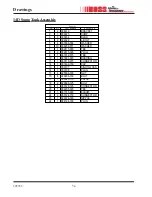
Page 52: ...1 10 6 TEE 902415 060 1 7 PLUG 902915 020 2 8 TEE 961912 075 1 9 BUSHING 907603 020 1 10 CONNECTOR 960112 075 1 11 CAP 301466 150 1 12 SIGHTGLASS 300107 1 13 PLUG 300108 1 14 NUT 925506 198 4 15 BOLT 929806 100 4 16 RELIEF 300023 175 1 17 BOLT 929806 125 2 18 CONNECTOR 960120 125 1 19 TEE 902205 025 1 20 ELBOW 901515 060 1 21 CONNECTOR 960124 150 2 22 NIPPLE 922224 000 1 23 PLUG 984724 188 1 24 ...

Page 53: ...53 309743 Drawings 10G RSC9 SumpTankAssembly cont 3 22 21 11 9 10 14 3 1 6 5 16 15 6 6 18 13 22 12 7 17 4 19 20 2 8 24 23 1 8 ...

Page 54: ...10 6 TEE 902415 060 1 7 PLUG 902915 020 2 8 TEE 961912 075 1 9 BUSHING 907603 020 1 10 CONNECTOR 960116 075 1 11 CAP 301466 150 1 12 SIGHTGLASS 300107 1 13 PLUG 300108 1 14 NUT 925506 198 4 15 BOLT 929806 100 4 16 VALVE 300023 175 1 17 BOLT 929806 125 2 18 CONNECTOR 960120 125 1 19 TEE 902205 025 1 20 ELBOW 901515 060 1 21 CONNECTOR 960124 150 2 22 NIPPLE 922224 000 1 23 PLUG 984724 188 1 24 ...

Page 55: ...55 309743 Drawings 14D SumpTankAssembly cont 3 22 21 9 10 14 3 1 6 5 16 15 6 6 18 13 22 12 7 17 4 19 20 2 8 24 23 1 11 8 ...

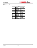
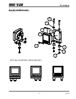
Page 56: ...T 924304 145 2 3 BOLT 929104 150 2 4 WASHER 938604 071 4 5 DECAL 309643 1 6 DECAL 310071 2 7 SPACER 301713 2 8 CABLE 309702 1 NS SCREW 992304 100 4 NS WASHER 938904 090 4 NS WASHER 938804 090 4 NS HARNESS 40062 1 NS HARNESS 309452 1 NS HARNESS 309451 1 NS BOLT 929104 075 2 NS B CANAssembly Drawings ...

Page 57: ...57 309743 5 4 3 5 6 1 2 7 8 OPTIONAL MOUNTING CONFIGURATIONS Drawings B CANAssembly cont ...

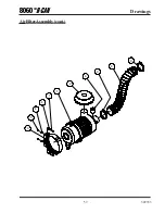
Page 58: ...IPTION PART NUMBER QTY ITEM ASSY 309408 1 1 CAP 309413 1 2 BAND 309414 1 3 WASHER 938205 071 4 4 NUT 925505 273 2 5 INDICATOR 309415 1 6 BOLT 929105 150 2 7 HOSE 301785 300 10FT 8 CLAMP 301786 300 2 9 AirFilterAssembly Drawings ...

Page 59: ...59 309743 5 4 4 7 3 1 2 6 9 8 9 Drawings AirFilterAssembly cont ...

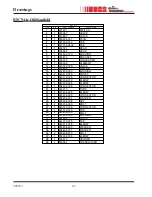
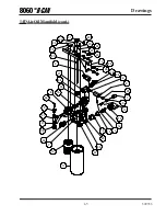
Page 60: ... 030 BUSHING 16 2 960412 075 NIPPLE 17 1 960112 075 CONNECTOR 18 1 987302 012 ELBOW 19 1 987305 025 ELBOW 20 1 988204 025 CONNECTOR 21 1 304210 TUBE 22 1 977604 025 ELBOW 23 1 987204 025 CONNECTOR 24 4 938206 071 WASHER 25 2 925506 198 NUT 26 2 929704 050 BOLT 27 1 960120 125 CONNECTOR 28 1 961912 075 TEE 29 2 929806 150 BOLT 30 1 907600 005 BUSHING 31 1 307855 VALVE 32 1 961712 075 TEE 33 1 96021...

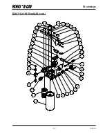
Page 61: ...61 309743 11 7 14 15 16 13 18 5 1 3 19 29 10 24 25 23 22 26 21 9 28 17 27 12 6 2 20 24 32 31 A B C I P 30 34 33 16 8 35 37 36 38 39 40 4 Drawings 10GAirOil Manifold cont ...

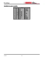
Page 62: ...BUSHING 907604 030 1 15 NIPPLE 960412 075 2 16 CONNECTOR 960112 075 1 17 ELBOW 987302 012 1 18 ELBOW 987305 025 1 19 CONNECTOR 988204 025 1 20 TUBE 304210 1 21 ELBOW 977604 025 1 22 CONNECTOR 987204 025 1 23 WASHER 938206 071 4 24 NUT 925506 198 2 25 BOLT 929704 050 2 26 CONNECTOR 960120 125 1 27 TEE 961912 075 1 28 BOLT 929806 150 2 29 BUSHING 907600 005 1 30 VALVE 307855 1 31 TEE 961712 075 1 32...

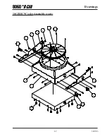
Page 63: ...63 309743 Drawings RSC9AirOil Manifold cont 11 7 14 15 16 13 18 5 1 3 19 29 10 24 25 23 22 26 21 9 28 17 27 12 6 2 20 24 32 31 A B C I P 30 16 8 34 36 35 37 38 39 33 4 ...

Page 64: ...USHING 907604 030 1 15 NIPPLE 960412 075 2 16 ELBOW 987302 012 1 17 ELBOW 987305 025 1 18 CONNECTOR 988204 025 1 19 TUBE 304210 1 20 ELBOW 977604 025 1 21 CONNECTOR 987204 025 1 22 WASHER 938206 071 4 23 NUT 925506 198 2 24 BOLT 929704 050 2 25 CONNECTOR 960120 125 1 26 TEE 961912 075 2 27 BOLT 929806 150 2 28 BUSHING 907600 005 1 29 VALVE 307855 1 30 ELBOW 987305 012 1 31 WASHER 938808 200 2 32 W...

Page 65: ...65 309743 Drawings 14DAirOil Manifold cont 11 14 15 16 13 17 5 1 3 18 28 10 23 24 22 21 25 20 9 27 26 12 2 19 23 30 A B C I P 29 31 16 8 32 34 33 35 36 37 4 38 6 38 38 27 7 39 ...

Page 66: ...N PART NUMBER QTY ITEM COOLER 300014 1 1 VENTURI 304454 1 2 FAN ASSY 310077 1 3 NUT 925305 283 4 4 BOLT 929705 100 20 5 ELBOW 960212 075 2 6 NUT 961505 140 16 7 RIVET 943104 038 4 8 RELAY 301755 012 1 9 BRACKET 301784 L 1 10 BRACKET 301784 R 1 11 HARNESS 307862 1 NS ...

Page 67: ...67 309743 Drawings 10G RSC9 CoolerAssembly cont 10 6 1 7 5 6 5 8 4 5 11 9 2 3 ...

Page 68: ...ART NUMBER QTY ITEM COOLER 300014 1 1 VENTURI 304454 1 2 FAN ASSY 310077 1 3 NUT 925305 283 4 4 BOLT 929705 100 20 5 ELBOW 960216 075 2 6 NUT 961505 140 16 7 RIVET 943104 038 4 8 RELAY 301755 012 1 9 BRACKET 301784 L 1 10 BRACKET 301784 R 1 11 HARNESS 307862 1 NS ...

Page 69: ...69 309743 Drawings 14D CoolerAssembly cont 6 6 5 4 11 10 8 9 7 5 5 2 1 3 ...

Reviews: