Inspection and maintenance
57
Greenstar 8000 Style – 6720883855 (2019/01)
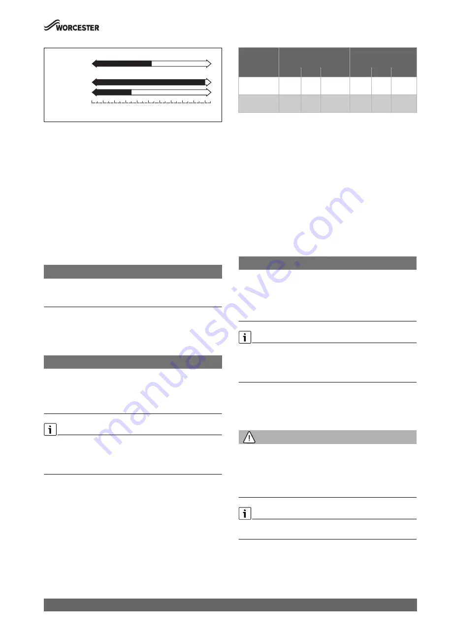
Fig. 75 Fan pressure test values
If the manometer reading is within tolerance
, between the appliance
output value [P] mbar and -9.0 mbar.
▶ The heat exchanger/exhaust path/siphon does not require attention.
If the manometer reading is out of tolerance
, between 0 mbar and the
appliance output value [P] mbar then carry out the following checks.
▶ Check that the siphon is not restricted or blocked.
▶ Check the exhaust paths for restrictions.
▶ Clean the heat exchanger with a suitable cleaning tool, refer to
cleaning section.
▶ Re-check the fan pressure readings.
If the boiler, after completing the above checks, fails the fan pressure
test then contact Worcester, Bosch Group for advice.
▶ Replace test point cover after completing pressure check.
8.6
Check working gas inlet pressure
NOTICE:
Gas inlet pressure
▶ Do not continue with the other checks if the correct gas inlet pressure
can not be achieved.
▶ Check the gas supply working pressures in the system conform to the
readings shown in the table shown in section 6.6 "Checking gas inlet
pressure".
8.7
Flue gas analysis
NOTICE:
Combustion testing
▶ Combustion testing must be carried out by a competent person.
Testing must not be attempted unless the person carrying out the
combustion check is equipped with a calibrated flue gas analyser
conforming to BS 7967 and is competent in its use.
Flue gas analysis
▶ Ensure that the gas inlet pressure has been checked and is
satisfactory.
▶ Refit the test point plugs after the test has been completed.
▶ Set the appliance to maximum and minimum output in chimney
sweep mode for the flue gas analysis checks (
chapter 6.4).
▶ Check that the readings conform to those given in the following
tables. In addition to CO and CO/CO
2
ratio checks also check the
maximum and minimum CO
2
percentage reading.
Table 22 CO
2
and O
2
contents
If the CO
2
is out of tolerance then please check:
▶ The gas inlet pressure.
▶ The gas rate.
▶ The fan test pressure.
▶ The flue and air intake, plus any possible blockages in the condensate
disposal.
▶ The condition of burner.
▶ For leaks or obstructions in the exhaust paths.
▶ CO
2
is correctly adjusted.
The gas valve and venturi are factory set and should not need to be
adjusted, if found to be out of tolerance and when all other possible
causes have been checked, please contact the Worcester Bosch Group
Helpline 0330 123 3366.
8.8
Checking the flue integrity
NOTICE:
▶ Check flue joints are secure, the terminal and the terminal guard, if
fitted are clear and undamaged.
▶ Combustion testing must be carried out by a competent person.
Testing must not be attempted unless the person carrying out the
combustion check is equipped with a calibrated Flue Gas Analyser
conforming to BS 7967 and is competent in its use.
Flue gas analysis
▶ Ensure that the gas inlet pressure has been checked and is
satisfactory.
▶ Refit the test point plugs after the test has been completed.
▶ Refer to section 6.10 "Checking flue integrity" and check that the
readings conform to those given, confirming flue system and
combustion circuit are ok.
8.9
Cleaning the siphon and heat exchanger
WARNING:
Gaskets and seals - gas related components
▶ Replace gaskets and seals when disturbing gas related components
(e.g. burner, electrode assembly etc.), after cleaning the heat
exchanger.
▶ Do not attempt the cleaning procedure unless new gaskets and seals
are available.
There is an optional tool available to assist in cleaning the heat
exchanger, part number 7 719 001 996.
FAN PRESSURE TEST
Appliances
0
-6
-5
-4
-3
-2
-1
-8
-7
-10
-9
mbar
GR8700iW 30:
- 10.0
GR8700iW 35:
- 3.5
- 4.8
Clean the Heat Ex.
Heat Ex. ok
0010025222-001
Maximum rated output
Minimum rated output
Gas type
CO
2
O
2
CO
CO
2
O
2
CO
Natural gas
9.5 %
± 0.4
4.0 % <250ppm 8.6 %
± 0.4
5.5 % <75ppm
Liquid
propane (LPG)
10.8 %
± 0.4
4.6 % <250ppm 10.2 %
± 0.4
5.5 % <75ppm


