background image

1 695 656 135

2011-01-12

Robert Bosch GmbH

�4  |  WBE 4100  |  Funcionamiento y navegación menú

es

� .2 

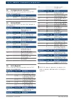
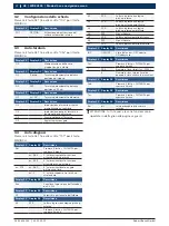
Configuración de la tarjeta

Pulsar la tecla SET hasta que aparezca escrito "TOL" 
después la tecla MM/INCH.

Display IZQ  Display DCHA

Descripción 

POT

OFF/ON

Activación y desactivación del ca-
libre automático calibre interno

� .� 

Autocalibrado

Pulsar la tecla SET hasta la escritura"CAL" después la 
tecla MM/INCH.

Display IZQ  Display DCHA

Descripción 

C-1 


Memorización del cero  
grupo brida y eje

Display IZQ  Display DCHA

Descripción 

D-1

0 osup

Regulación potenciómetro di-
stancia: posición de reposo

Display IZQ  Display DCHA

Descripción 

D-2

200

Medición potenciómetro di-
stancia: posición a 20 cm

Display IZQ  Display DCHA

Descripción 

H-1

ej.: 14"

Medición  potenció-
metro diámetro

Display IZQ  Display DCHA

Descripción 

C-2


Introducción dimensio-
nes rueda y memoriza-
ción  desequilibrio rueda

C-3


Impostacion peso de me-
dida y lanzamiento con pe-
so en el interior

C-4


Lanzamiento con el pe-
so en el exterior

C-5


Ajuste ángulo 

� .4 

Auto-diagnosis

Pulsar la tecla SET hasta que aparezca escrito "TST" 
después la tecla MM/INCH.

Display IZQ 

Display DCHA

Descripción 

Msr


Pulsar la tecla + DISTAN-
ZA para desplegar el menú 


ej.: 384

1° valor visualizado: tensión 
medida pick-up interno (pa-
stilla electromagnética) 


ej.: 603

2° valor visualizado: tensión  
medida  pick-up externo

ej.: 179

ej.: 580

3° valor visualizado: án-
gulo diferencia de fase 


ej.: 2

4° valor: relación entre 
los pick-up redondeada

Display IZQ 

Display DCHA

Descripción 

Enc


Visualiza la posición  del 
encoder de 0 a 255

Display IZQ 

Display DCHA

Descripción 

SP


Velocidad en giros/
minuto del eje

Display IZQ 

Display DCHA

Descripción 

A0

510

Lectura entrada analó-
gica pick-up externo


Pulsar la tecla + DISTAN-
ZA para desplegar el menú 

A1

510

Lectura entrada analógica 
pick-up interno

A2

510

Lectura entrada analógica 
pick-up exterrno amplificada

A3

510

Lectura entrada analógica 
pick-up interno amplificada

A4

###

No utilizado

A5

200

Lectura potenció-
metro distancia 

A6

###

No utilizado

A7

200

Lectura potenció-
metro diámetro

Display IZQ 

Display DCHA

Descripción 

INP

ON/OFF

Estado del cárter: OFF 
abierto, ON bajado

Display IZQ 

Display DCHA

Descripción 

Cnt


Pulsar la tecla + DISTAN-
ZA para desplegar el menú

1

500

Número de lanzamientos

 totales (ej.: 1500)


6

Número de lanzamientos 
diarios (desde cuando se 
ha encendido la máquina)

Display IZQ 

Display DCHA

Descripción 

Led


Pulsar la tecla + DISTAN-
ZA para desplegar el menú 

Display IZQ 

Display DCHA

Descripción 

Tar


Pulsar la DISTAN-
ZA para desplegar el menú 

Display IZQ 

Display DCHA

Descripción 

Rel

off

Inicio proceso equilibracion  
relativa


!

ATENCIÓN: Todas las opciones y las diversas fun-
ciones se explican detalladamente en las páginas 
siguientes.

Summary of Contents for WBE 4100

Page 1: ...WBE 4100 en Repair instructions Wheel balancer de Instandsetzungsanleitung Wheel balancer es Instructions de réparation Wheel balancer it Istruzioni di riparazione Wheel balancer ...

Page 2: ...1 695 656 135 2011 01 12 Robert Bosch GmbH 2 WBE 4100 2WBE 4100 ...

Page 3: ...1 695 656 135 2011 01 12 Robert Bosch GmbH 3 Inhaltsverzeichnis Deutsch 4 Contents English 18 Índice Español 32 Indice Italiano 46 ...

Page 4: ...tzliche Informationen Einschrittige Handlungsaufforderung nur aus einem Schritt bestehende Handlungsaufforderung Zwischenergebnis innerhalb einer Handlungsauf forderung wird ein Zwischenergebnis sichtbar Endergebnis am Ende einer Handlungsaufforderung wird das Endergebnis sichtbar 1 2 WBE 4100 Entsorgung Elektro und Elektronik Altgeräte einschließ lich Leitungen und Zubehör sowie Akku und Batterie...

Page 5: ...uchtstelle LED 4 Einstelltasten ABSTAND Felge 5 Einstelltasten DURCHMESSER Felge 6 Einstelltasten BREITE Felge 7 SPLIT Taste 8 Taste zur Auswahl der Maßeinheit für die Breite und den Durch messer der Felge MM INCH 9 Taste für Steuerfunktionen SET 10 Taste zur Auswahl des Wuchtprogramms MODE 11 STOPP Taste 11 START Taste Das Menü der Auswuchtmaschine kann in verschiedene Untermenüs untergliedert we...

Page 6: ...ren Messsensor gemessene Spannung Bsp 603 2 angezeigter Wert vom äußeren Messsensor gemessene Spannung Bsp 179 Bsp 580 3 angezeigter Wert Phasen unterschied in Graden Bsp 2 4 angezeigter Wert auf gerundetes Verhältnis zwi schen den Messsensoren Display LI Display RE Beschreibung Enc Zeigt die Position des Enco ders zwischen 0 bis 255 an Display LI Display RE Beschreibung SP Geschwindigkeit der Umd...

Page 7: ...fen ein Kontakt könnte defekt sein R R Die Karte austauschen Kap 9 HINWEIS Um festzustellen ob das Problem am Relais oder auf der Karte zu suchen ist muss nur die Steckverbindung der Kar te von der elektrischen Anlage abgezogen werden falls das Pro blem anschließend weiter besteht das Relais und die Karte prüfen Bei mehreren nacheinander folgen den Messläufen mit demselben Rad wer den unterschiedl...

Page 8: ...t sich nicht Die elektrische Anlage anhand des elektri schen Schaltplans Nr 654144 prüfen Err 17 Das Gewicht liegt außerhalb des Einstellungs bereichs das für die Wuchtung des Rades er forderliche Gewicht beträgt mehr als 250 gr R R Sicherstellen dass das Rad korrekt auf dem Flansch befestigt wurde R R Erneut die äußere Position ermitteln ein Auswuchtgewicht von 100 gr anbringen und erneut einen M...

Page 9: ...zu aktivieren Um das Konfigurationsmenü zu öffnen muss solange die Taste SET gedrückt werden bis auf dem linken Dis play die Meldung SET erscheint Anschließend muss sofort innerhalb von max 1 5 Sek die Taste MM INCH gedrückt werden Um die Werte zu ändern die Tasten DURCHMESSER drücken In der folgenden Tabelle ist die einzige für die Modelle WBE 4100 aktivierbare Funktion aufgeführt Display LI Disp...

Page 10: ...ie Eichung wird auf diese Weise automatisch und dauerhaft gespeichert Nach der Durchführung des ersten Abschnitts der Kalibrierung C 1 oder über die Taste SET gelangt man innerhalb des Eichungsmenüs zur Kalibrierung der auto matischen Messarme Auf dem linken Display erscheint die Meldung D 1 Den inneren Messarm mit Millimeterskala für die Abstandseinstellung in Ruheposition bringen auf der Tastatu...

Page 11: ...i Signalen das Signal des inneren Messsensors und das Signal des äußeren Messsensors kann beobachtet werden dass zwischen beiden Signa len eine Phasendifferenz besteht d h unterschiedliche Spannungswerte abgelesen werden Betrachtet man beispielsweise die nebenstehende Figur 4 so steht das Signal in schwarzer Farbe für die Spannung des äuße ren Sensors und das rote Signal für die Spannung des inner...

Page 12: ...chi ne zählt über haupt keinen Zählschritt R R Sicherstellen dass der Enco der korrekt angeschlossen ist R R Den Encoder Code 653272 auswechseln 8 3 Sp Das Kürzel steht für die Funktion mit der direkt die von der Welle erreichte Geschwindigkeit in Umdrehungen Minute kontrolliert wird Durch Schließen der Radschutzabdeckung und Drücken der Taste START kann die bei der Wuchtung erreichte Geschwindigk...

Page 13: ...e Messsensoren neu positionieren R R Den Messsensor auswech seln in unserem Bei spiel ist der äußere Sen sor auszuwechseln Die Radauswuchtmaschi ne muss häufig neu ka libriert werden R R Die Messsensoren neu positionieren R R Beide Messsenso ren auswechseln Falls sich im Rahmen eines Wartungseingriffes die Mög lichkeit bieten sollte empfehlen wir immer zuerst mit dem Austausch der Hauptkarte Kap 9...

Page 14: ...skabel aus wechseln Code 654085 R R Die Potentiometer Einheit Code 654107 auswechseln Der Wert beginnt z B bei 600 und bleibt an der Endskala stehen Den Potentiometer neu po sitionieren siehe nachfol gende Anweisungen Nachdem der Potentiometer ausgetauscht wurde oder nachdem festgestellt wurde dass die Feststellschraube sich gelockert hat müssen vor Eichung die folgenden Operationen durchgeführt w...

Page 15: ...r für die Eichung der Messarme fortset zen Kap 7 8 5 INP Mit dieser Abkürzung wird die Funktion bezeichnet die direkt die Betriebsweise des Mikroschalters an der Ra dschutzabdeckung steuert Bei einer korrekt funktionierenden Maschine erscheint bei Absenkung der Radschutzabdeckung auf dem rech ten Display die Meldung ON Display LI Display RE Beschreibung INP ON OFF Status der Radschutzabdeckung OFF...

Page 16: ...play erscheint nun 0 0 die Prüfung der Radauswuchtmaschine fortsetzen wie im Kapitel der Einleitung dargestellt ACHTUNG Um diese Funktion zu deaktivieren muss die Radauswuchtmaschine ausgeschaltet werden 9 Karte auswechseln HINWEISE FÜR DIE WARTUNG Falls die Karte ausgewechselt werden muss Cod 654044 müssen die korrekten Konfigurationen vorge nommen Kap 5 und Kap 6 und die gesamte Prozedur für die...

Page 17: ...1 695 656 135 2011 01 12 Robert Bosch GmbH Elektrische Anlage 17 de 11 Elektrische Anlage ...

Page 18: ...e instructions for a procedure that can be completed in just one step Intermediate result an intermediate result is dis played during a procedure Final result the final result is displayed at the end of the procedure 1 2 WBE 4100 Disposal Old electrical and electronic devices including cables and accessories or batteries must be disposed of separate to household waste 1 Symbols used 18 1 1 Documen...

Page 19: ... 6 Setting buttons of the WIDTH of the circle 7 SPLIT button 8 Button to select the unit of measurement for the width or the diameter of the circle MM INCH 9 Button for the control functions SET 10 Setting button for the balancing programme MODE 11 STOP button 11 START button We can divide the balancing machine menu in several submenus Configuration of the use Configuration of the board Self calib...

Page 20: ...own menu ex 384 1 shown value measured tension left pick up Ex 603 2 shown value meas ured tension right pick up ex 179 Ex 580 3 shown value phase an gle difference Ex 2 4 value Ratio between the rounded off pick ups Left Display Right Display Description Enc It shows the position of the encoder from 0 to 255 Left Display Right Display Description SP Speed in turn min of the shaft Left Display Rig...

Page 21: ...and if the problem is the relay or the board you need to remove the board connector from the cir cuit If the problem persists check the relay and the board Unbalance values are not steady if you make several consecutive launches on the same wheel variations higher than 5 gr Recalibrate the balancing machine chapter 7 R R Check the tension and the phase of the pick ups chapter 8 1 and chapter 8 4 1...

Page 22: ...een fixed correctly on the flange R R Search for the external position anyway ap ply a 100 grams weight and launch again R R If the problem persists do the calibration again chapter 7 Err 18 The wheel data have not been set up R R Set up the wheel data before making the measure launch R R Check that the gauges are enabled chapter 6 Err 19 The signal at the entry of the right pick up is less intens...

Page 23: ...the flange in the following cases R R when making a launch without the wheel the ma chine has unbalances higher than 5 grams R R when you move from a flange to another motorcycle flange cone flange or 3 4 5 holes To enter the calibration menu press SET until when the notice CAL will appear on the left display and after 1 5s max press MM INCH Now the left display will show the notice C 1 Left Displ...

Page 24: ... calibration the machine works in a correct way but it does not memorize the parametres permanently In order to check you must R R turn off the machine R R wait until 10sec R R turn it on again R R check that the gauges acquire the measures in a cor rect way R R verify that the machine balances in a perfect way 8 Auto diagnosis menu On every Bosch balancing machine you can find an auto diagnosis m...

Page 25: ...TANCE If we check the ratio between the pick ups and the dif ference of phase and we find values out of tolerances we must substitute the board chapter 9 or substitute the sensors of the pick ups chapter 8 4 2 8 2 Enc It indicates the function to directly check the encoder the number of spaces goes from 0 to 255 To enter the menu when you see Test see above press SET again Left Display Right Displ...

Page 26: ...the middle of the reading scale R R if you push the shaft down the value decreases to zero R R if you lift the shaft up the value increases up to the end of the scale NOTES OR THE ASSISTANCE The sensors code 654432 are identical and in order to distinguish them during the production they mount the red pick up outside and the black one inside Here you can find some examples and possible solu tions ...

Page 27: ...ed R R Substitute the connec tion cable code 654085 R R Substitute the potenti ometer code 654107 The value is blocked be tween 100 and 1000 R R Check that the lock nut is properly fixed R R Substitute the connec tion cable code 654085 R R Substitute the potenti ometer cod 654107 The value starts from ex 600 and blocks at the end of the scale Reposition the potentiometer See the following Instruct...

Page 28: ... When the cover goes down if the machine is working correctly you will see the notice ON on the right dis play Left Display Right Display Description INP ON OFF State of the carter OFF open ON down NOTES FOR THE ASSISTANCE Defect Correction The value does not change R R Check the connection on the board R R Check that the cam code 653035 that starts the mi cro switch works properly R R Substitute ...

Page 29: ...urn off the balancing machine 9 Substitution of the board NOTES FOR THE ASSISTANCE When you need to substitute the board code 654044 remember to set up the correct configurations chapter 5 and chapter 6 and complete the calibration proce dure chapter 7 1 Power supply 2 Encoder 3 Pick up int 4 Pick up ext 5 Calibers 6 F 400mAT 7 F1 500mAT 8 Buzer Bip NOTE The sensors code 654432 are identical In or...

Page 30: ...1 695 656 135 2011 01 12 Robert Bosch GmbH 30 WBE 4100 Electrical system en 11 Electrical system ...

Page 31: ...1 695 656 135 2011 01 12 Robert Bosch GmbH Electrical system 31 en ...

Page 32: ...nformaciones útiles Instrucción de actuación de un paso Instrucción de actuación compuesta por un solo paso Resultado intermedio Dentro de una instrucción de actuación se puede ver un resultado intermedio Resultado final Al final de una instrucción de actua ción se puede ver el resultado final 1 2 WBE 4100 Eliminación Los aparatos eléctricos y electrónicos usa dos incluyendo los cables y accesorio...

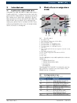
Page 33: ... DIÁMETRO llanta 6 Teclas regulación ANCHURA llanta 7 Tecla SPLIT 8 Tecla selección unidad de medida para anchura o diámetro llanta MM INCH 9 Tecla funciones de control SET 10 Tecla selección programa de equilibrado MODE 11 Tecla STOP 11 Tecla START Se puede subdividir el menú de la máquina de equilib rado en diversos sub menús Configuración de uso Configuración de la tarjeta Autocalibrado Auto di...

Page 34: ...o pa stilla electromagnética ej 603 2 valor visualizado tensión medida pick up externo ej 179 ej 580 3 valor visualizado án gulo diferencia de fase ej 2 4 valor relación entre los pick up redondeada Display IZQ Display DCHA Descripción Enc Visualiza la posición del encoder de 0 a 255 Display IZQ Display DCHA Descripción SP Velocidad en giros minuto del eje Display IZQ Display DCHA Descripción A0 5...

Page 35: ... levador o en la tarjeta es suficiente desconectar de la in stalación eléctrica el conector de la tarjeta si conti nuara el problema revisar el relevador y la tarjeta Realizando diversos lanzamientos conse cutivos en la misma rueda los valo res de desequilibrio no son constan tes variaciones superiores a lo 5 gr R R Volver a realizar la medición cap 7 R R Comprobar la tensión y fase de los pick up...

Page 36: ...00 gramos y efectuar un nuevo lanzamiento R R Si el error persiste hacer una nueva medición cap 7 Err 18 Datos de la rueda no registrados R R Introducir los datos de la rueda antes de rea lizar el lanzamiento de medición R R Controlar que los calibres no estén activos cap 6 Err 19 La señal a la entrada del pick up de la derecha es inferior al del pick up de la izquierda R R Probable inversión en l...

Page 37: ... de medición de la equilibradora se divide en tres partes diferentes R R Medición de la brida R R Medición de los calibres electrónicos R R Auto calibrado con rueda y peso de referencia La medición de la brida memoriza el valor de desequi librio del grupo eje y adaptador para la rueda Se aconseja hacer la medición de la brida en los siguientes casos R R cuando haciendo un lanzamiento sin rueda señ...

Page 38: ...DISTAN ZA Display IZQ Display DCHA Descripción D 2 200 Medición potenciómetro di stancia posición a 200 mm En el display de la izquierda aparece H 1 Montar una rueda de hierro 14 o 15 Llevar el cursor interno contra el borde interno de la llanta y introducir en el teclado el valor correcto se me moriza manteniendo en posición el palpador y pulsando la tecla DISTANZA Display IZQ Display DCHA Descri...

Page 39: ...abla que sigue para calcu lar la diferencia de tensión se tiene que dividir el valor del pick up externo por el interno obteniendo así la relación entre ambos 603 384 1 57 Display IZQ Display DCHA Descripción Msr Pulsar la tecla DISTAN ZA para desplegar el menú ej 384 1 valor visualizado ten sión medida pick up interno ej 603 2 valor visualizado tensión medida pick up externo ej 179 ej 580 3 valor...

Page 40: ... de lectu ra R R empujando el eje hacia abajo el valor incremente hasta el final de la escala R R alzando hacia arriba el eje el valor disminuya hasta cero 8 4 2 A1 Señal del pick up interno Ahora el sensor está montado en la otra posición En fase de revisión del aparato comprobar que R R el valor de reposo esté en la mitad de la escala de lectura R R empujando el eje hacia abajo el valor disminuy...

Page 41: ...a el recorrido el valor no se quede bloquea do NOTA PARA LA ASISTENCIA Se presenta la necesidad de comprobar los valores de los potenciómetros cuando durante la fase de intro ducción de las medidas la máquina visualiza valores inaceptables y tampoco después de la medición de los calibres se resuelve el problema Defecto Corrección El valor permanece bloqueado al final de la escala o entre 0 y 40 R ...

Page 42: ...úes la tecla MM INCH pulsar SET hasta que aparezca escrito A0 pulsar la tecla DISTANZA hasta que aparezca escrito A7 manteniendo visualizado el valor en la pantalla des bloquear el tornillo sobre la tuerca A manteniendo el calibre en reposo girar el potenció metro hasta el valor de 200 50 bloquear el tornillo de fijación comprobar el correcto funcionamiento durante el recorrido volver a cerrar la ...

Page 43: ...ne memorizado cerrar el cárter de protección y hacer un segundo lanzamiento en las pantallas aparecerá 0 0 realizar el control de la equilibradora como en el capítulo introductorio ATENCIÓN Para desactivar las funciones apagar la equilibradora 9 Sustitución tarjeta NOTA PARA LA ASISTENCIA Cuando se presenta la necesidad de sustituir la tarjeta cod 654044 recordar establecer las correctas confi gur...

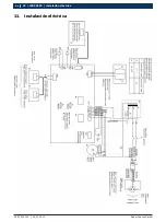
Page 44: ...1 695 656 135 2011 01 12 Robert Bosch GmbH 44 WBE 4100 Instalación eléctrica es 11 Instalación eléctrica ...

Page 45: ...1 695 656 135 2011 01 12 Robert Bosch GmbH Instalación eléctrica 45 es ...

Page 46: ...oni utili Istruzioni rapide istruzioni costituite solo da una fase Risultato intermedio all interno di un istruzione è visibile un risultato intermedio Risultato finale al termine di un istruzione è visibile il risultato finale 1 2 WBE 4100 Smaltimento Gli apparecchi elettrici ed elettronici fuori uso con relativi cavi accessori accumulatori e batterie devono essere smaltiti separatamen te dai rif...

Page 47: ...rchio 6 Tasti impostazione LARGHEZZA cerchio 7 Tasto SPLIT 8 Tasto selezione unità di misura per larghezza o diametro cerchio MM INCH 9 Tasto funzioni di controllo SET 10 Tasto selezione programma di equilibratura MODE 11 Tasto STOP 11 Tasto START Si può suddividere il menù dell equilibratrice in diversi sottomenù Configurazione d uso Configurazione della scheda Auto taratura Auto diagnosi Tenendo...

Page 48: ... es 603 2 valore visualizzato tensione misurata pick up esterno es 179 es 580 3 valore visualizzato angolo differenza di fase es 2 4 valore rapporto tra i pick up arrotondato Display SX Display DX Descrizione Enc Visualizza la posizione dell encoder da 0 a 255 Display SX Display DX Descrizione SP Velocità in giri minuto dell albero Display SX Display DX Descrizione A0 510 Lettura ingresso analogic...

Page 49: ... si trova nel relè o sulla scheda è sufficiente staccare dall impianto elettrico il connettore del la scheda se dovesse persistere controllare il relè e la scheda Eseguendo diversi lanci consecutivi sul la stessa ruota i valori di squilibrio non so no costanti variazioni superiori ai 5 gr R R Rifare la taratura cap 7 R R Controllare tensione e fase dei pick up cap 8 1 e cap 8 4 1 R R Controllare i...

Page 50: ...rna applicare un pe so di 100 grammi ed effettuare un nuovo lancio R R Se l errore persiste fare una nuova taratura cap 7 Err 18 Dati della ruota non impostati R R Impostare i dati della ruota prima di eseguire il lancio di misura R R Controllare che i calibri non siano attivi cap 6 Err 19 Il segnale all ingresso del pick up di dest ra è inferiore a quello del pick up di sinistra R R Probabile inv...

Page 51: ... Taratura della flangia R R Taratura dei calibri elettronici R R Auto taratura con ruota e peso campione La taratura della flangia memorizza quello che è il valore di squilibrio dell insieme albero e adattatore per la ruota Si consiglia di fare la taratura della flangia nei seguenti casi R R quando facendo un lancio senza ruota la macchina chiama degli squilibri superiori ai 5 grammi R R quando si...

Page 52: ...splay di sinistra compare H 1 Montare una ruota in ferro di 14 o 15 Portare il cursore interno contro il bordo interno del cerchio ed impostare sulla tastiera il valore corretto si memorizza tenendo in posizione il tastatore e premen do il tasto DISTANZA Display SX Display DX Descrizione H 1 es 14 Taratura potenziometro diametro La fase di taratura dei calibri è terminata NOTE PER L ASSISTENZA Può...

Page 53: ...ando come esempio la tabella sottostante per calcolare la differenza di tensione bisogna dividere il valore del pick up esterno per quello interno ottenendo così il rapporto tra i due 603 384 1 57 Display SX Display DX Descrizione Msr Premere il tasto DISTANZA per scorrere il menù es 384 1 valore visualizzato tensione misurata pick up interno es 603 2 valore visualizzato tensione misurata pick up ...

Page 54: ...ore di riposo sia a metà della scala di lettura R R spingendo l albero verso il basso il valore incrementi fino a fine scala R R alzando verso l alto l albero il valore diminuisca fino a zero 8 4 2 A1 Segnale del pick up interno Ora il sensore è montato nell altra posizione In fase di controllo dell apparecchiatura verificare che R R il valore di riposo sia a metà della scala di lettura R R spinge...

Page 55: ...trollare il corretto funzionamento del potenzio metro estrarre il calibro e verificare che durante l intera corsa il valore non resti bloccato NOTE PER L ASSISTENZA Si presenta la necessità di controllare i valori dei poten ziometri quando in fase di inserimento delle misure la macchina visualizza valori inaccettabili e anche dopo la taratura dei calibri il problema non viene risolto Difetto Corre...

Page 56: ...alla scritta TST e poi il tasto MM INCH premere SET fino alla scritta A0 premere il tasto DISTANZA fino alla scritta A7 tenendo visualizzato il valore sulla scheda sbloccare il grano sull albero A tenendo il calibro a riposo girare il potenziometro fino al valore di 200 50 bloccare il grano sull albero controllare il corretto funzionamento durante la corsa richiudere la macchina procedere con la t...

Page 57: ...hiudere il carter di protezione e fare un secondo lancio sui display sara visualizzato 0 0 procedere col controllo dell equilibratrice come da capitolo introduttivo ATTENZIONE Per disattivare la funzione spegnere la equilibratrice 9 Sostituzione scheda NOTE PER L ASSISTENZA Quando si presenta la necessità di sostituire la scheda cod 654044 ricordarsi di impostare le corrette confi gurazioni cap 5 ...

Page 58: ...1 695 656 135 2011 01 12 Robert Bosch GmbH 58 WBE 4100 Impianto elettrico it 11 Impianto elettrico ...

Page 59: ...1 695 656 135 2011 01 12 Robert Bosch GmbH Impianto elettrico 59 it ...

Page 60: ...Robert Bosch GmbH Diagnostics Franz Oechsle Straße 4 73207 Plochingen DEUTSCHLAND www bosch com bosch prueftechnik bosch com Printed in Germany Imprimé en Allemagne 1 695 656 135 2011 01 12 ...

Reviews: