6 720 220 380
Revised 06-13 Subject to change without prior notice
TsTbT4h2CP series
7
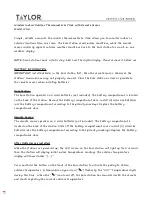
Terminal Designations on the TSTBT4H2CP Thermostat Series
3 Heat / 2 Cool Conventional System
3 Heat / 2 Cool Heat Pump System
4 Heat / 2 Cool Heat Pump System
C
24 Volt Common
24 Volt Common
24 Volt Common
R
24 Volt Power
24 Volt Power
24 Volt Power
O
Energized in Cooling
Energize Reversing Valve in Cooling
Energize Reversing Valve in Cooling
B
Energized in Heating
Energize Reversing Valve in Heating
Energize Reversing Valve in Heating
W1
Heating - 1st Stage Aux
Heating - 1st Stage Aux
Heating - 1st Stage Aux / Emergency Heat
W2
Heating - 2nd Stage Aux
Emergency Heat Relay
Heating - 2nd Stage Aux
Y1
Compressor - 1st Stage Cooling
Compressor - 1st Stage Heating/Cooling
Compressor - 1st Stage Heating/Cooling
Y2
Compressor - 2nd Stage Cooling
Compressor - 2nd Stage Heating/Cooling
Compressor - 2nd Stage Cooling
G
Fan Relay
Fan Relay
Fan Relay
DH
"Cool to Dehumidify Relay
(Cooling Mode Only)”
“Cool to Dehumidify Relay
(Cooling Mode Only)”
“Cool to Dehumidify Relay
(Cooling Mode Only)”
HUM
"Humidifi er Contact Relay
(Dry Contact-Heating Mode Only)”
“Humidifi er Contact Relay
(Dry Contact-Heating Mode Only)”
“Humidifi er Contact Relay
(Dry Contact-Heating Mode Only)”
HUM
“Humidifi er Contact Relay
(Dry Contact-Heating Mode Only)”
“Humidifi er Contact Relay
(Dry Contact-Heating Mode Only)”
“Humidifi er Contact Relay
(Dry Contact-Heating Mode Only)”
ALR
This terminal is used only for Bosch / Florida Heat Pump Equipment. This connection is used for fault code communication from the
UPM board in the heat pump. The fault type being transmitted will be displayed on the thermostat. Do not use with any other equipment.
Caution
TSTBT4H2CP Thermostat Series Wiring
Notes: Bosch Water Source Heat Pumps
utilize “O” type reversing valve operation. If
your heat pump utilizes “B” type reversing
valve operation, substitute the wiring for the
“O” terminals for “B”.
TemPeraTure sensor ConneCTions
zonb-las---m--a return air
Temperature sensor
Optionally, a temperature sensor can be installed in the
return air duct. This sensor is automatically detected by
the TRM and used to control the equipment should the
communication between the thermostat and TRM fail.
This insures the indoor temperature does not drop below
55°F or rise above 85°F.
Use AWG 18–22 thermostat wire to connect the sensors
to the TRM.
Ts1 and Ts2
Temperature sensor 1 and Temperature sensor 2 inputs on
the TRM can be confi gured in the thermostat setup menu as
an outdoor temperature sensor, a leaving air temperature
sensor, or as a remote room temperature sensor.
Either TS1 or TS2 can be designated as the outside air
temperature sensor, however once one of the input
sensors are designated as the outdoor temperature
sensor, the option will not be available for the other
sensor input in the menu setup. The same logic applies for
the leaving air temp. You cannot have two sensor inputs
designated as outdoor temperature or leaving air temp.
For the remote room temperature sensor function, either
TS1 or TS2 can be desingnated or both can. Two remote
room temp sensors are allowed.
Ts1 used as outdoor Temperature sensor
An outdoor temperature sensor is required for dual fuel
heal pumps and for automatic emergency heat activation
in cold weather. The sensor should be installed under the
eves and in the shade.
Temperature sensor Connections
Summary of Contents for TSTBT4H2CP-M--A
Page 21: ...6 720 220 380 Revised 06 13 Subject to change without prior notice TSTBT4H2CP SERIES 21 ...
Page 22: ...6 720 220 380 Subject to change without prior notice Revised 06 13 22 TSTBT4H2CP SERIES ...
Page 23: ...6 720 220 380 Revised 06 13 Subject to change without prior notice TSTBT4H2CP SERIES 23 ...