40/52 Commissioning
Bosch Rexroth AG
, VT-MRMA1-1, RE 30214-B/03.2019
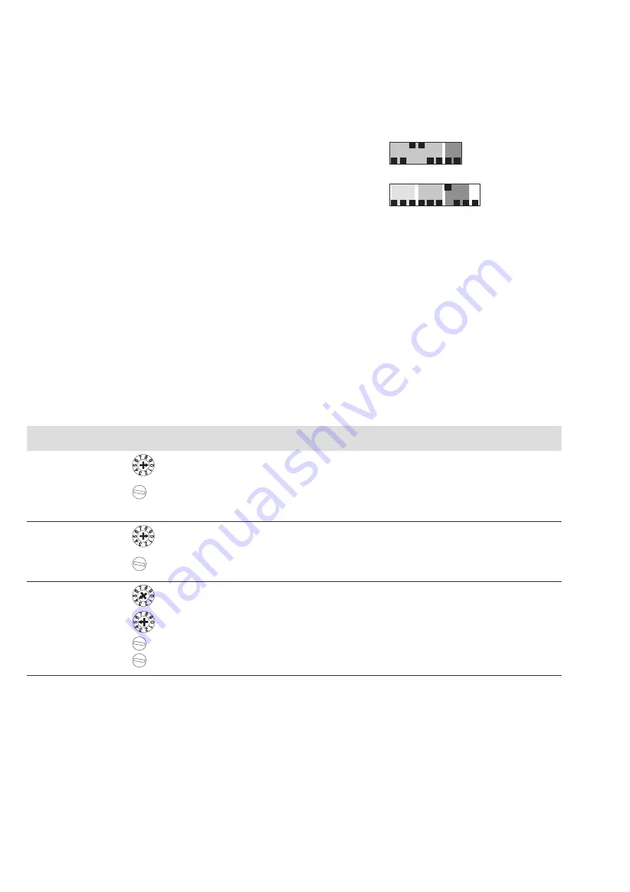
• The factory settings of DIL switch S1 (current or voltage input for the pressure
command value) and DIL switch S2 (switching thresholds for the actual pressure
value) are as follows (see also chapter 8.1.1 on page 33):
Fig. 19: Factory setting of S1/S2
8.3 Fine tuning of the complete system
Preconditions:
The system-specific connections must have been made!
The hydraulic oil must have reached its (regulated) operating temperature.
1.
Set the DIL switches on the printed-circuit board of the amplifier module
according to your individual requirements (see chapter 8.1.1 on page 33).
2.
Switch the amplifier module on.
3.
Switch the hydraulic system on.
4.
Adjust the system by taking the following measures:
Table 34: Setting steps
No. Signal
Adjustment
element
Setting
1
Pressure
command value
zero point
= 0
Zw
v
1.
The external pressure command value feedforward to 0 %.
2.
Set measuring point selector switch to 0
When adjusting Zw, potentiometer Gw must not be turned to the left-hand limit stop (=
0 %)!
3.
Use zero point potentiometer Zw to set the measuring signal at test jack v to 0 V
±5 mV (= 0 %).
2
Maximum value
of pressure
command value
= 0
Gw
v
1.
Calibrate the zero point before calibrating the maximum value.
2.
Select an external pressure command value of 100 %.
3.
Set measuring point selector switch to 0.
4.
Use zero potentiometer Gw to set the measuring signal at test jack v to 10 V ±5 mV (=
0 %).
3
Ramp times
= 4
= 5
t<
t>
v
1.
Select the potentiometer to be adjusted by means of the measuring point selector
switch (position 4 for ramp Up t< and position 5 for ramp Down t>)
2.
Adjust the ramp times according to the formula or the table “ramp time setting” (see
“Ramp generator (3)“ on page 15) at test jack v.
OFF
8
7
6
5
4
3
2
1
ON
8
7
6
5
4
3
2
1
9 10
OFF
ON
Factory setting S1
Factory setting S2


