About this product 19/52
RE 30214-B/03.2019, VT-MRMA1-1,
Bosch Rexroth AG
Actual pressure value
Pressure switch signal A
(terminal 13)
Pressure switch signal B
(terminal 14)
Upper switching threshold exceeded
(excessive pressure)
24 V (HIGH)
0 V (LOW)
Cable break of actual pressure value
cables or pressure transducer supply
cables
0 V (LOW)
0 V (LOW)
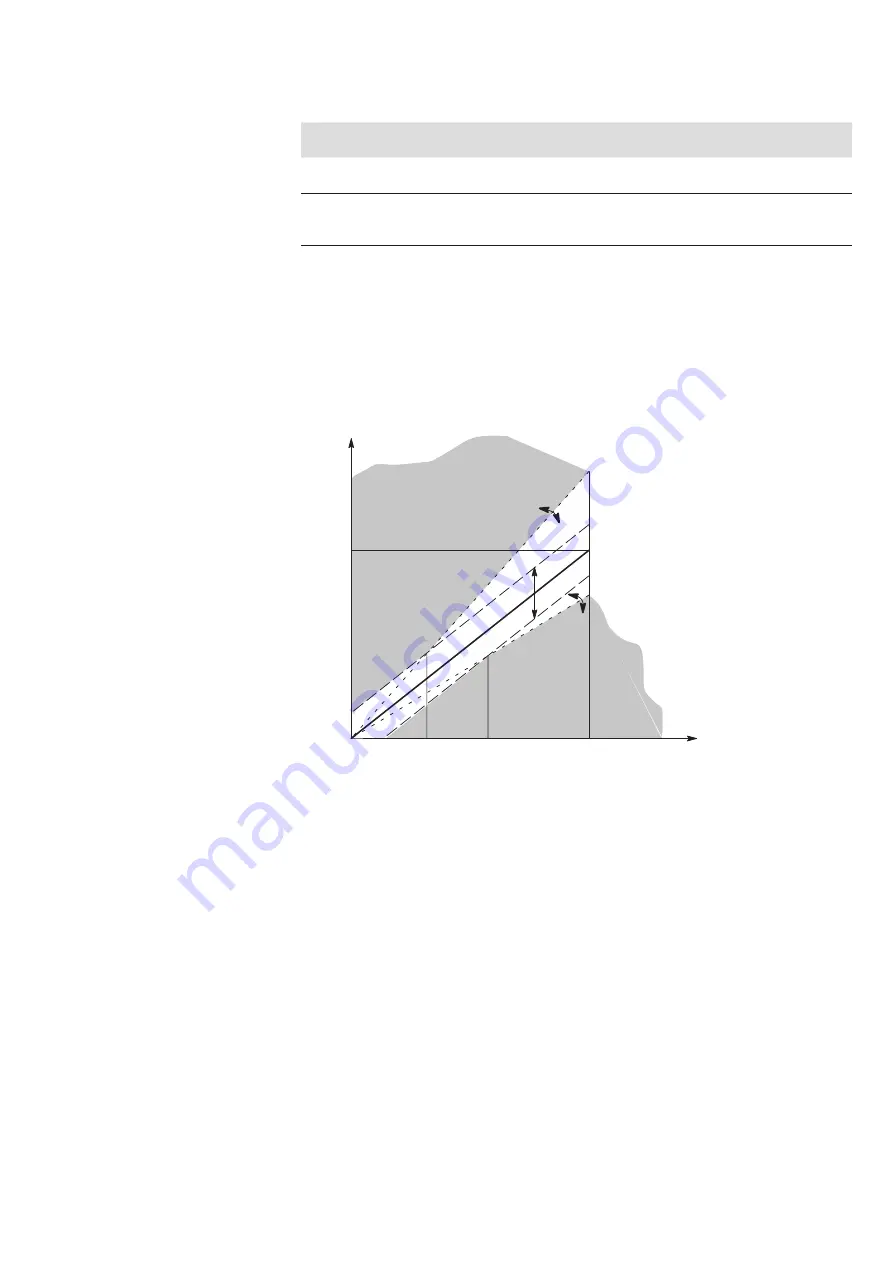
Setting the pressure switch thresholds:
The upper and lower switching thresholds each are composed of a
relative
and an
absolute
amount. The relative switching threshold is defined in % and refers to the
currently set pressure command value. The absolute switching threshold is defined
in % and refers to the nominal value (= maximum pressure) of the selected pressure
level (see figure below):
Fig. 4: Pressure switch thresholds
Overlapping (p1, p2) of the relative and the corresponding absolute switching
thresholds results in an envelope curve in the form of a ”funnel” (see figure above).
As long as the actual pressure value remains within the ”funnel limits” at a given
pressure command value, both pressure switch signals A and B are HIGH. If the
pressure exceeds or falls below one of the two limits (actual pressure value is in the
gray area), the corresponding pressure switch signals falls to LOW.
5.2.6 Monitoring functions
The monitoring functions of the amplifier module are to detect faults in the system
and in the supply lines and to initiate appropriate measures in the event of a fault.
B = LOW
A = LOW
100 %
100 %
p
2
p
1
Upper relative switching threshold
(in % of current command value)
Upper absolute switching threshold (in %
of nominal value of the pressure level)
Ideal valve characteristic curve
Lower absolute switching threshold (in %
of nominal value of the pressure level)
Lower relative switching threshold
(in %of current command value)
Actual pressure value
Pressure command value


