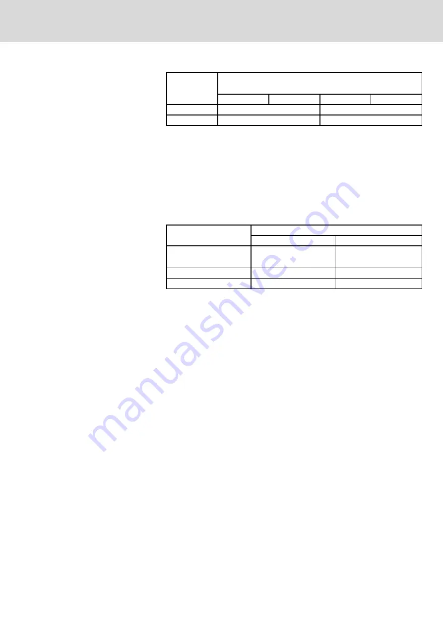
Direction
Maximum permissible vibration load (10-2,000 Hz)
for MKE motors with subject to encoder design
A
B
C
D
Axial
10 m/s²
10 m/s²
Radial
30 m/s²
10 m/s²
Fig.9-8:
Permissible vibration load for MKE motors
9.8
Shock
The shock load of the motors is indicated by providing the maximum permit‐
ted acceleration in non-stationary use, such as during transport.
Function-impairing effects are avoided as long as the limits specified are
kept.
Based on DIN EN 60721-3-3 and DIN EN 60068-2-6, the following values re‐
sult for Rexroth motors:
Frame size
Maximum allowed shock load (6 ms)
Axial
Radial
MKE037
MKE047
10 m/s²
1,000 m/s²
MKE098
10 m/s²
300 m/s²
MKE118
10 m/s²
200 m/s²
Fig.9-9:
Permitted shock load for MKE motors
9.9
Output Shaft
9.9.1
Plain Shaft
The standard design recommended for MKE motors provides a non-positive
shaft-hub connection without play and excellent running smoothness. Use
clamping sets, clamping sleeves or clamping elements to couple the machine
elements to be driven.
9.9.2
Output Shaft with Keyway
The optional key according to DIN 6885, sheet 1, version 08-1968, permits
the form-fitting transmission of torques with constant direction, with low re‐
quirements for the shaft-hub connection.
DOK-MOTOR*-MKE*GEN2***-PR06-EN-P
Rexroth MKE Synchronous Motors for Potentially Explosive Areas acc. to ATEX and UL/CSA
Bosch Rexroth AG
81/135
Operating Conditions and Application Notes
LSA Control S.L. www.lsa-control.com [email protected] (+34) 960 62 43 01


