


Installation 57/104
RE 92076-01-B/10.2017, A4... with HS5E pilot control valve/Series 3x,
Bosch Rexroth AG
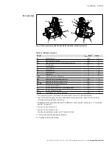
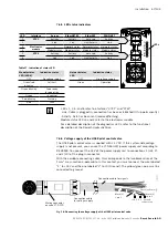
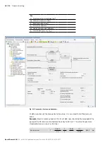
7.6.5 LED status indicators
LEDs 1, 2, 5, and 6 refer to interfaces “X7E1” and “X7E2”
- Link: Cable is plugged in, connection has been established (lit up permanently)
- Activity: Data has been sent/received(flashing)
Module status LEDs 3 and 4 refer to the electronics module
For a detailed description of the diagnostics LEDs, refer to the functional
description of the Rexroth HydraulicDrive.
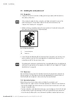
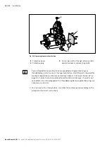
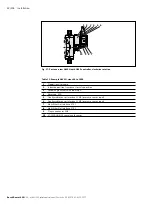
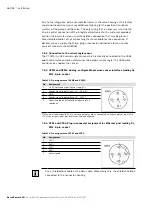
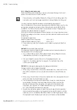
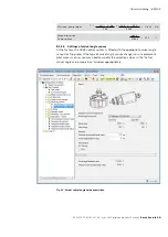
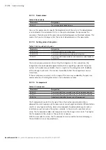
7.6.6 Voltage supply of the HS5E pilot control valve
The HS5E pilot control valve is supplied with 24 V DC. If this system-side voltage
supply is not present, you can use the VT-NE30-2X/ power supply unit according to
RE 29929. You connect the 24 V of the power supply unit to connections 1 (+24 V)
and 2 (L0) of the plug-in connector.
With the available connecting cable, this corresponds to the two black wires of the
1 mm² cross-section 3-pole cable. In this context, you must connect the wire labeled
“1” to +24 V and the one labeled “2” to L0 (Ground). The yellow/green wire must be
connected to ground.
Fig. 18: Connecting the voltage supply of the HS5E pilot control valve
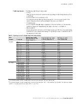
Table 17: Indication of status LED
Module status
LED (LED 4)
Indication status
network status
LED
Indication status
OFF
No voltage supply
OFF
No voltage supply
Green/red
blinking
Self-test
Green
Operation
Green blinking
Drive ready
for operation
Green
in control
Red blinking
Warning
Red
Fault
LED
Interface
Sercos
EthernET/IP
EtherCAT
PROFInET
1
X7E1
Activity
Activity
not used
Activity
2
Link
Link
Link/Activity
Link
3
Electronics
module
S
Network status Network status Network status
4
Module status Module status
Module status
Module status
5
X7E2
Activity
Activity
not used
Activity
6
Link
Link
Link/Activity
Link
Mating connector
on valve VT-DFPD
Connection cable
for voltage supply
Connection cable for signals
Green/yellow
=
Black (2)
= pin 2
Ground
connection
0 V
+24 V
Black (1)
= pin 1