background image

MIC IP ultra 7100i 

 MIC IP starlight 7100i

(Optional) Installing a Sunshield | en

35

Bosch Security Systems

Installation Manual

2019-07-03 | 0.17 |

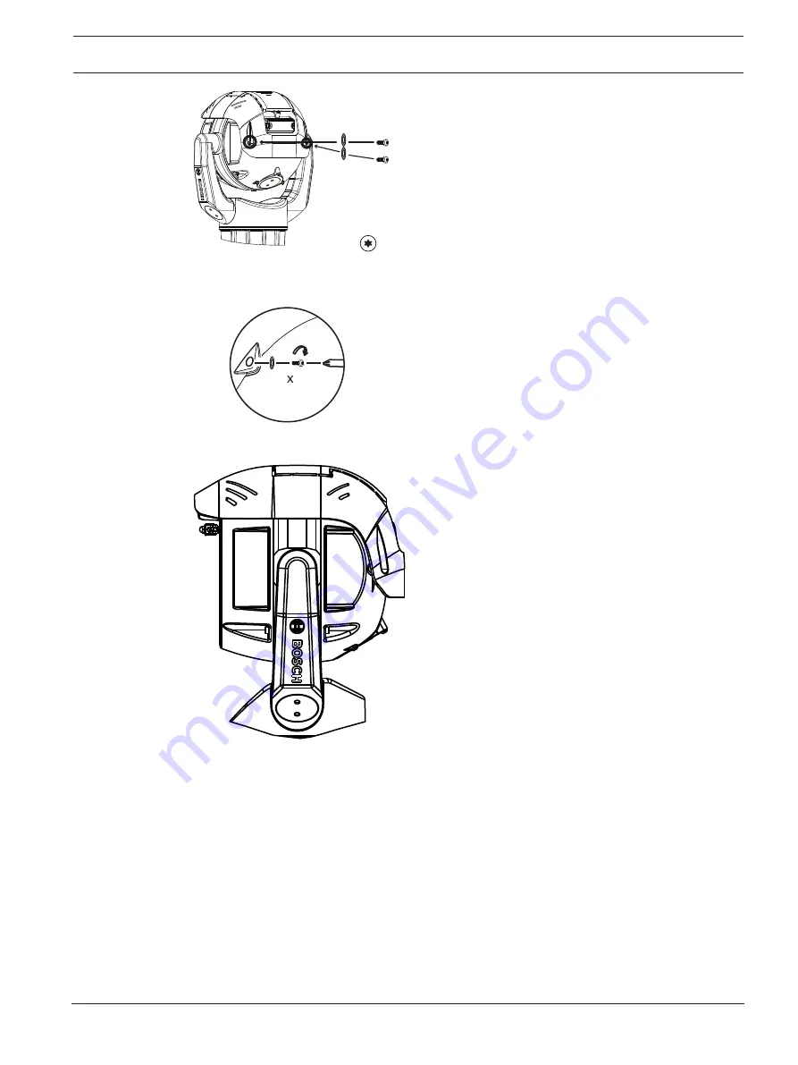
M4 x 8

2.2 N m

(19.5 in lb)

T20

2

6.

Note that when you install the sunshield correctly, the sunshield appears as in the
following figure.

Figure


10.1: Sunshield installation is complete.

Summary of Contents for MIC IP ultra 7100i

Page 1: ...MIC IP ultra 7100i MIC IP starlight 7100i MIC 7504 MIC 7522 en Installation Manual ...

Page 2: ......

Page 3: ...mera in Inverted Orientation 22 6 Optional Installing an SD card 24 7 Optional Configuration Programming in the Shipping Box 25 8 Optional Configuration Programming on a Temporary Table top Stand 26 9 Installing a MIC Camera on a Hinged DCA 27 10 Optional Installing a Sunshield 33 11 Optional Installing the Illuminator 36 12 Optional Canting the Camera 38 13 Connections 42 13 1 About Camera Power ...

Page 4: ...pment of products the content of the manual may change without notice Bosch Security Systems accepts no liability for damage resulting directly or indirectly from faults incompleteness or discrepancies between the manual and the product described 1 2 Legal Information Copyright This manual is the intellectual property of Bosch Security Systems and is protected by copyright All rights reserved Trad...

Page 5: ... Voltage inside the product If not avoided this will result in an electrical shock serious bodily injury or death Warning Medium risk Indicates a potentially hazardous situation If not avoided this may result in minor or moderate injury Caution Low risk Indicates a potentially hazardous situation If not avoided this may result in property damage or risk of damage to the unit Notice This symbol ind...

Page 6: ...TALLATION A READILY ACCESSIBLE 2 POLE DISCONNECT DEVICE WITH A CONTACT SEPARATION OF AT LEAST 3 mm MUST BE INCORPORATED Warning ROUTING OF EXTERNAL WIRING MUST BE DONE THROUGH A PERMANENTLY EARTHED METAL CONDUIT Warning THE CAMERA MUST BE MOUNTED DIRECTLY AND PERMANENTLY TO A NON COMBUSTIBLE SURFACE Warning Risk of bodily injury Do not put a canted 35 camera in an upright position on the camera ba...

Page 7: ...ian installer Notice Risk of injury or damage To prevent injury to your hands or damage to the wiper do not touch the wiper with your hands especially when the wiper is moving Notice Always use a shielded twisted pair STP connection cable and a shielded RJ45 network cable connector where the camera is used outdoors or the network cable is routed outdoors Always use shielded cables connectors in de...

Page 8: ...for use in public areas only U S federal law strictly prohibits surreptitious recording of oral communications Accessories Do not place this unit on an unstable stand tripod bracket or mount The unit may fall causing serious injury and or serious damage to the unit Use only with mounting solutions specified by the manufacturer When a cart is used use caution and care when moving the cart unit comb...

Page 9: ... any heat sources such as radiators heaters or other equipment including amplifiers that produce heat Moving Before moving the unit disconnect both the 24 VAC connection and the Ethernet cable connection if using PoE Outdoor signals The installation for outdoor signals especially regarding clearance from power and lightning conductors and transient protection must be in accordance with NEC725 and ...

Page 10: ...ICES 003 of Industry Canada These limits are designed to provide reasonable protection against harmful interference when the equipment is operated in a commercial environment This equipment generates uses and radiates radio frequency energy and if not installed and used in accordance with the instruction manual may cause harmful interference to radio communications Operation of this equipment in a...

Page 11: ...r very prolonged exposures where direct ocular exposures may be expected An example of Risk Group 1 is a domestic battery operated torch flashlight Exposure Hazard Value EHV is a ratio of the Exposure Level distance exposure time to Exposure Limit Value ELV When EHV is greater than 1 the device has exceeded the Exposure Limit Values for a particular Risk Group The ELV is the level where optical ra...

Page 12: ...sch com Customer Service Telephone 888 289 0096 Fax 585 223 9180 Email security sales us bosch com Technical Support Telephone 800 326 1450 Fax 717 735 6560 Email technical support us bosch com Canada Telephone 514 738 2434 Fax 514 738 8480 Europe Middle East Africa and Asia Pacific Regions Please contact your local distributor or Bosch sales office Use this link https www boschsecurity com corpor...

Page 13: ...issing notify your Bosch Security Systems Sales or Customer Service Representative Do not use this product if any component appears to be damaged Please contact Bosch Security Systems in the event of damaged goods The original packing carton if undamaged is the safest container in which to transport the unit and must be used if returning the unit for service Save it for possible future use Caution...

Page 14: ...ase gasket 1 RJ45 coupler 1 MAC address labels 1 Quick Installation Guide 1 Safety instructions 2 2 Additional Tools The following table lists additional tools not supplied by Bosch that may be required to install a MIC camera or its accessories 1 Phillips head screwdriver to secure the ground lug of the camera 1 Adjustable wrench or socket set to secure the base of the camera to mounting accessor...

Page 15: ...mera s ruggedized design meets customer expectations in demanding environments that exceed the capabilities of conventional IP cameras Even in installations subject to harsh shock vibration conditions and or extreme weather the camera provides high quality video images Make sure that the installation conditions comply with the specified stresses of vibration and shock as mentioned in the datasheet...

Page 16: ... a replacement 1 Select the Mounting Location and Orientation 2 Install the appropriate 24 VAC power supply VG4 A PSU1 or VG4 A PSU2 or midspan 60 W version or 95 W version and or the alarm washer interface MIC ALM WAS 24 each sold separately Refer to the Installation Manual of the appropriate device for installation instructions 3 Install grounded metal conduit user supplied to the MIC DCA sold s...

Page 17: ...C IP fusion 9000i MIC IP ultra 7100i and MIC IP starlight 7100i cameras To have an installation rated IP67 you must use the appropriate IP67 Connector Kit from Bosch Confirm that no residual water or moisture is in the bottom of camera Ground the camera as described in the chapter Installing a MIC Camera on a Hinged DCA You can install the camera in one of three orientations upright straight up 90...

Page 18: ...mbined weight of the camera and mounting hardware sold separately under all expected conditions of load vibration wind and temperature Caution Risk of lightning strikes If the camera is installed in a highly exposed location where lightning strikes may occur then Bosch recommends installing a separate lightning conductor within 0 5 m 1 6 ft of the camera and at least 1 5 m 4 9 ft higher than the c...

Page 19: ...fore installation and periodically inspect the metal parts of the camera for paint that is chipped or otherwise damaged If you notice any paint damage return the unit for a replacement Avoid installation practices that may bring the camera s metal mountings in contact with materials such as stainless steel Such contacts can result in galvanic corrosion and degrade the cosmetic appearance of the ca...

Page 20: ...20 en Mounting MIC IP ultra 7100i MIC IP starlight 7100i 2019 07 03 0 17 Installation Manual Bosch Security Systems 55 55 90 90 A u t o P i v o t Figure 5 1 Tilt range MIC IP ultra 7100i ...

Page 21: ...le Wall Mount MIC SPR BD WD MG MIC SCA BD WD MG MIC WMB BD WD MG Figure 5 2 Typical Wall mount configuration Note Always install an SCA when you install a wall mount for any installation configuration Route cables through the bottom of the SCA to prevent water from running into the side or top of the SCA along the cables Pole Mount The figure below identifies the three mounting accessories each so...

Page 22: ...to Inverted complete the following steps 1 Remove the camera from the shipping box 2 Apply power to the camera 3 Access the web browser of the camera 4 Access the page Configuration 5 Navigate to Camera Installer Menu Orientation 6 Select Inverted The camera head will rotate automatically into inverted position 180 Note the position of the visor when the camera is installed in inverted orientation...

Page 23: ...light 7100i Mounting en 23 Bosch Security Systems Installation Manual 2019 07 03 0 17 The figure that follows shows the camera installed in inverted orientation on a pole Figure 5 6 MIC camera mounted in inverted orientation on pole ...

Page 24: ...MIC 7522 Z30xR 1 Use a T20 Torx driver to remove the two 2 fasteners from the SD card cover on the rear of the camera head 2 Pull off the SD card cover Allow the cover and the O ring seal to hang loose from the tether Note Do not drop the fasteners 3 Install a standard SD card 4 If necessary put the O ring seal into the cover 5 Put on the cover 6 Install the two 2 fasteners that you removed in ste...

Page 25: ...o rotate If you must change the camera s orientation to Inverted remove the camera from the box and configure it by following the steps in Optional Configuration Programming on a Temporary Table top Stand 1 Remove the packing material to access the camera s electrical connectors 2 Supply power to the camera and Connect the Camera to the Network page 43 Note that the wiper moves one to three times ...

Page 26: ... 2 Remove the foam covering the head of the camera 3 Remove the camera still in the foam from the box Place the camera upright on a flat horizontal surface 4 Supply power to the camera and Connect the Camera to the Network page 43 Note that the wiper moves one to three times across the camera window and then returns to parked position 5 Configure the camera Refer to the separate User Manual for de...

Page 27: ...less steel plain washers M8 1 O ring 80 mm x 3 mm 1 conduit adapter male M25 to female 3 4 NPT Available in specific regions only 1 Blanking plug M25 x 1 5 with O ring 1 Quick Installation Guide Additional Tools Required 1 Torx driver T25 to loosen and tighten the hook bolts 1 Wrench driver to secure M8 bolts supplied to mount the camera onto the DCA 1 Wrench driver to secure user supplied bolts m...

Page 28: ...cation using user supplied hardware item 1 Bosch recommends stainless steel bolts and washers 2 Attach user supplied conduit or glands to the side hole or to the bottom hole If applicable use the conduit adapter male M25 to female in NPT item 2 included with the DCA 3 Route cables into the DCA item 4 either through the bottom or from the side 4 Use the blanking plug and O ring item 3 included with...

Page 29: ... Camera on a Hinged DCA en 29 Bosch Security Systems Installation Manual 2019 07 03 0 17 2x T25 Torx 5 Insert the O ring item 1 6 Loosen the Torx bolts two 2 turns items 2 Slide the hook up item 3 Tighten the bolts to hold the hook in place temporarily item 4 ...

Page 30: ...mount of grease to the primary O ring to hold it in place 8 Push the wires from the camera base into the DCA while positioning the base pin of the camera under the DCA hook item 1 Avoid pinching the wires item 2 Loosen the hook bolts and then slide the hook down to secure the camera pin Fully tighten the hook bolts item 3 9 Carefully tilt the camera to the side with the pin under the hook ...

Page 31: ... Ease the camera into position do not allow it to fall unassisted into rotated position or allow head to slam into any surface or object 10 Make the appropriate electrical connections Refer to the chapter Connections for more information 11 Connect the lead from the camera pigtail to the ground post on the pan base The connection for the customer should be to the lead from the post ...

Page 32: ...7100i MIC IP starlight 7100i 2019 07 03 0 17 Installation Manual Bosch Security Systems 17 N m 12 5 ft lb M8 x4 12 Carefully tip the camera to its final position Avoid pinching wires between the camera base and the DCA Insert four washers and hex bolts supplied ...

Page 33: ...ad screws 1 Pair of diagonal cutters to remove the plastic insert for the illuminator from the sunshield shell if necessary Notice Install the applicable accessories illuminator sunshield before you cant the camera 1 If you will install an illuminator on a unit mounted in upright orientation Cut out the inset area in the sunshield shell with a pair of diagonal cutters The inset area provides space...

Page 34: ...P ultra 7100i MIC IP starlight 7100i 2019 07 03 0 17 Installation Manual Bosch Security Systems 2 4 Make sure that the tabs in the sunshield lock into place in the camera head 5 Install the M4 x 10 screws Tighten the screws to 2 2 N m 19 5 in lb ...

Page 35: ...ng a Sunshield en 35 Bosch Security Systems Installation Manual 2019 07 03 0 17 M4 x 8 2 2 N m 19 5 in lb T20 2 6 Note that when you install the sunshield correctly the sunshield appears as in the following figure Figure 10 1 Sunshield installation is complete ...

Page 36: ...th illuminator and sunshield accessories install the illuminator first If the camera will be mounted inverted you must rotate the tilt head before attaching the illuminator 1 Apply power 2 Connect to your network 3 From the web browser access the camera s Configuration page Select Camera Installer Menu Orientation 4 Select Inverted Click Set to confirm the selection The camera head will rotate aut...

Page 37: ...MIC IP ultra 7100i MIC IP starlight 7100i Optional Installing the Illuminator en 37 Bosch Security Systems Installation Manual 2019 07 03 0 17 ...

Page 38: ...he tilt limits of the camera prevent correct operation in inverted and canted orientation Warning Risk of bodily injury Unplug the device from its power source before canting the device After removing the screws from the yoke arms support the camera head so that it doesn t tilt downward unexpectedly and pinch fingers or other body parts Notice Risk of damage to the camera Do not under any circumst...

Page 39: ...se steps 1 Remove the yoke cap item 2 in the figure below on one yoke arm of the camera using the supplied spanner wrench item 1 Repeat for the second arm Figure 12 2 Remove the yoke caps with the spanner tool 2 Remove the two 2 screws at the bottom of one yoke arm using a wrench user supplied as described below Notice Risk of damage to the device Without the yoke arm screws in position the camera...

Page 40: ...in the yoke arms in the following sequence ABCD 7 Using a torque wrench user supplied tighten the screws to the proper torque using the sequence described in the table below 8 Recheck all four screws to ensure the proper torque value Do not use grease on the screws 1 2 5mm Hex T30 Torx 7 5 Nm 5 5 ft lb 17 Nm 12 5 ft lb 3 4 D B D A C D C C B A B A D C B A 17 Nm 12 5 ft lb 17 Nm 12 5 ft lb 9 Attach ...

Page 41: ...s Installation Manual 2019 07 03 0 17 0 0mm 0 5mm Figure 12 5 Attach the yoke caps 10 Canting is complete Figure 12 6 Canting is complete 11 Change the camera orientation to Canted Complete the following steps Access the page Configuration Navigate to Camera Installer Menu Orientation Select Canted ...

Page 42: ...ly selects the High PoE Midspan and will draw minimal power from the auxiliary input 24 VAC If the High PoE Midspan power source fails the camera switches power input seamlessly to 24 VAC After the High PoE Midspan power source is restored the camera switches power input again to the High PoE Midspan Bosch recommends 24VAC power output of 24V at 100VA 4A with a slow blow fuse Camera models 60 W mi...

Page 43: ...e bundling requirements and limitations 13 4 Camera Connections All electrical and data connections from the camera are made from the connectors in the base of the camera For more information refer to the installation manual Power Supply Units AUTODOME VG5 and MIC IP Camera Models shipped with VG4 A PSU1 and VG4 A PSU2 Note If the MIC camera will be installed directly to a mounting surface instead...

Page 44: ...dspan no input or output connections 1 MIC camera 2 MIC Hinged DCA MIC DCA Hx 3 High PoE Network cable Cat5e Cat6 Shielded Twisted Pair STP user supplied between the camera and the High PoE Midspan 4 High PoE Midspan 5 Data only IP cable Cat5e Cat6 Shielded Twisted Pair STP user supplied between the High PoE Midspan and the head end network Note The total length of Cat5e Cat6 Shielded Twisted Pair...

Page 45: ... ALM WAS 24 1 MIC camera 2 MIC Hinged DCA MIC DCA Hx 3 RS 485 cable 3 conductor user supplied 4 Enclosure of MIC ALM WAS 24 5 Interface cable for 24 VAC for MIC ALM WAS 24 user supplied 6 24 VAC Power pack 1A 50 60 Hz user supplied 7 Washer pump accessory user supplied 8 Interface cable for washer control user supplied 9 Interface cables for alarm inputs and outputs user supplied 10 Switch monitor...

Page 46: ...ess the camera The image becomes frozen You cannot update the firmware The camera disconnects from the network at random and needs a reboot The camera no longer finds pre positions preset positions You cannot configure the camera using the web browser The camera has no video out Notice A factory default deletes all camera settings including passwords network settings and image settings Complete th...

Page 47: ...MIC IP ultra 7100i MIC IP starlight 7100i Troubleshooting en 47 Bosch Security Systems Installation Manual 2019 07 03 0 17 ...

Page 48: ...xternal wiper blade the device contains no user serviceable parts Contact your local Bosch service center for device maintenance and repair In the event of failure the device should be removed from site for repair On Site Inspection It is recommended that the device be inspected on site every six months to check mounting bolts for tightness security and any signs of physical damage Inspection of t...

Page 49: ...ty materials and components that can be reused This symbol means that electronic and electrical devices that have reached the end of their working life must be disposed of separately from household waste In the EU separate collecting systems are already in place for used electrical and electronic products Please dispose of these devices at your local communal waste collection point or at a recycli...

Page 50: ...tarlight 7100i 2019 07 03 0 17 Installation Manual Bosch Security Systems 18 Technical data For product specifications see the datasheet for your camera available on the appropriate product pages of the Online Product Catalog at www boschsecurity com ...

Page 51: ...nd lightning protection when installing outdoor cameras The following figure is an illustration of the proper configuration for installing IP PTZ cameras AUTODOME and MIC outdoors with surge and lightning protection Note that the illustration does not include representations of all models of AUTODOME and MIC cameras The illustration can represent any IP camera Mounting hardware varies between unit...

Page 52: ...air STP Ethernet cable Route the cable through grounded metal conduit Isolate high voltage power lines in a separate conduit 7 Equipment enclosure 8 Outdoor rated High PoE compatible midspan 9 Connect the Bus Bar to the Equipment Grounding Electrode 10 Outdoor High PoE compatible surge protection to protect indoor equipment 11 Equipment Grounding Electrode 12 Lightning Rod 13 Down Conductor refer ...

Page 53: ...MIC IP ultra 7100i MIC IP starlight 7100i Best Practices for Outdoor Installation 53 Bosch Security Systems Installation Manual 2019 07 03 0 17 ...

Page 54: ...54 Best Practices for Outdoor Installation MIC IP ultra 7100i MIC IP starlight 7100i 2019 07 03 0 17 Installation Manual Bosch Security Systems ...

Page 55: ......

Page 56: ...Bosch Security Systems B V Torenallee 49 5617 BA Eindhoven Netherlands www boschsecurity com Bosch Security Systems B V 2019 ...

Reviews: