


Allegiant Keyboards
Installation | en
17
Bosch Security Systems, Inc.
Instruction Manual
F.01U.127.290 | 2.0 | 2009.03
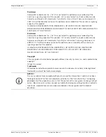
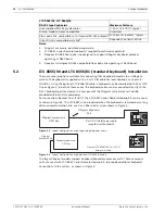
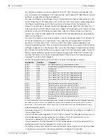
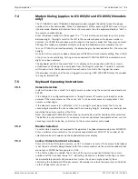
A modem interface requires the cable connections below. A user-supplied cable suitable for
RS-232 communications is required.
The modem on the Allegiant side must be set to an auto answer mode, and the modem on the
keyboard side must be set to an originate mode. In some cases, modem settings are
configured via dipswitches found on the back of the modem. In other cases, the modem must
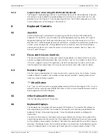
be connected to a PC for configuration. The below settings represent the dipswitch
configuration required for US Robotics Sportster modems.
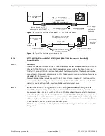
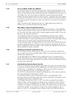
5.3.5
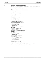
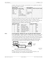
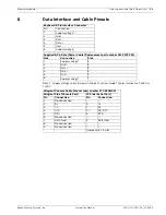
Console Expander Configuration when Using RS-232 Model Keyboards
RS-232 model keyboards may be connected to an Allegiant system using the LTC 8712 Series
Console Port Expander, as shown in
Figure 5.7
. An LTC 8712 Series Console Port Expander
can be configured to support up to four RS-232 Keyboard connections. Other devices, such as
a PC running the Allegiant Master Control software, can be connected to the unused ports of
the Port Expander. Because the Port Expander supports only a single baud rate for the
external connections, and the RS-232 keyboards require 9600 baud, all external devices
connecting to the Port Expander must be configured to for operation at this setting.
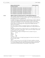
Figure 5.7
Configuration using LTC 8712 Series Console Port Expander
On Allegiant systems with a Printer port, up to two Console Port Expanders can be
connected, supporting a total of eight RS-232 model keyboards.
Allegiant System
RS-232 Keyboard
9-pin Console Port 25-pin Modem
25-pin Modem LTC 8557 Hookup kit Terminal
1 (Chassis Gnd)
1 (Chassis Gnd)
2
3
2 (Rx)
3 (Tx)
3
2
3 (Tx)
2 (Rx)
7
1
4 (CTS)
8 (DCD)
Tie pin 4 (RTS)
5 (RTS)
4 (RTS)
and Pin8 (DCD)
7 (Data Gnd)
7 (Data Gnd)
together
Tie pin 6 (DSR) and
pin 20 (DTR) together
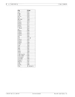
Allegiant-side Modem
Keyboard-side Modem
Dip Switch
Setting
Modem Function
Dip Switch
Setting
1
DOWN
DTR Override
1
DOWN
2
UP
Verbal Result Codes
2
UP
3
DOWN
Display Result Codes
3
DOWN
4
UP
Echo Offline Commands
4
UP
5
DOWN
Suppress Auto Answer
5
UP
6
DOWN
Carrier Detect Override
6
UP
7
DOWN
Load Factory Defaults
7
DOWN
8
DOWN
Smart Mode
8
DOWN
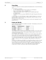
LTC 8712 Expander
Allegiant system main
CPU bay
Refer to text regarding setup of the Allegiant
& LTC 8712 to operate in Allegiant Keyboard
mode.
Junction box & power
adapter supplied with
LTC 8557 kit
User-supplied female
9-pin D connector.
3 m (10 ft) data/
power cable
supplied with
keyboard
User-supplied cable or other link
suitable for
full duplex RS-232 transmissions
at 9600 baud
Expander pin 2 (Rx) to Tx of link or directly to pin 3 of IntuiKey's 9 pin connector
Expander pin 3 (Tx) to Rx of link or directly to pin 2 of IntuiKey's 9 pin connector
Expander pin 7 (Gnd) to Data Gnd of link or directly to pin 5 of IntuiKey's 9 pin connector
1
2
3
4
1
2
3
4
5
6
7
8
9
0
Shot
Mon
Prod
Clr
BOSCH
Summary of Contents for LTC 8555/00
Page 1: ...Allegiant Keyboards LTC 8555 Series en Instruction Manual ...
Page 2: ......
Page 39: ......


