background image

2

en | Safety

Allegiant Keyboards

F.01U.127.290 | 2.0 | 2009.03

Instruction Manual

Bosch Security Systems, Inc.

11.

Power sources - 

Operate the unit only from the type of power source indicated on the 

label. Before proceeding, be sure to disconnect the power from the cable to be installed 

into the unit.

For battery powered units, refer to the operating instructions.

For external power supplied units, use only the recommended or approved power 

supplies.

For limited power source units, this power source must comply with 

EN60950

Substitutions may damage the unit or cause fire or shock.

For 24 VAC units, voltage applied to the unit's power input should not exceed ±10%, 

or 28 VAC. User-supplied wiring must comply with local electrical codes (Class 2 

power levels). Do not ground the supply at the terminals or at the unit's power 

supply terminals.

If unsure of the type of power supply to use, contact your dealer or local power 

company.

12.

Servicing -

 Do not attempt to service this unit yourself. Opening or removing covers may 

expose you to dangerous voltage or other hazards. Refer all servicing to qualified service 

personnel.

13.

Damage requiring service -

 Unplug the unit from the main AC power source and refer 

servicing to qualified service personnel when any damage to the equipment has 

occurred, such as:

the power supply cord or plug is damaged;

exposure to moisture, water, and/or inclement weather (rain, snow, etc.);

liquid has been spilled in or on the equipment;

an object has fallen into the unit;

unit has been dropped or the unit cabinet is damaged;

unit exhibits a distinct change in performance;

unit does not operate normally when the user correctly follows the operating 

instructions.

14.

Replacement parts - 

Be sure the service technician uses replacement parts specified by 

the manufacturer, or that have the same characteristics as the original parts. 

Unauthorized substitutions may cause fire, electrical shock, or other hazards.

15.

Safety check -

 Safety checks should be performed upon completion of service or repairs 

to the unit to ensure proper operating condition.

16.

Installation - 

Install in accordance with the manufacturer's instructions and in 

accordance with applicable local codes.

17.

Attachments, changes or modifications - 

Only use attachments/accessories specified by 

the manufacturer. Any change or modification of the equipment, not expressly approved 

by Bosch, could void the warranty or, in the case of an authorization agreement, authority 

to operate the equipment.

Summary of Contents for LTC 8555/00

Page 1: ...Allegiant Keyboards LTC 8555 Series en Instruction Manual ...

Page 2: ......

Page 3: ...ation 12 5 3 LTC 8555 02 and LTC 8555 03 RS 232 Protocol Model Installation 13 5 3 1 General 13 5 3 2 Keyboard Number Assignments when Using RS 232 Model Keyboards 13 5 3 3 Allegiant System Command Scripts for RS 232 Model Keyboards 14 5 3 4 Modem Interface Information when Using RS 232 Model Keyboards 16 5 3 5 Console Expander Configuration when Using RS 232 Model Keyboards 17 5 3 6 Login Feature...

Page 4: ...re position Scene 22 7 5 6 Recalling a Camera Pre position Scene 22 7 5 7 Activate Deactivate Auxiliary Function 22 7 5 8 Arm Disarm Individual Alarms 23 7 5 9 Arm Disarm All Alarms 23 7 5 10 Arm Disarm Monitor 23 7 5 11 Acknowledgment of Alarms 23 7 5 12 Load Clear a Sequence 23 7 5 13 Run a Sequence 24 7 5 14 Stop a Running Sequence 24 7 5 15 Controlling the Direction of a Sequence 24 7 5 16 Pro...

Page 5: ...s of any kind into this unit through openings as they may touch dangerous voltage points or short out parts that could result in a fire or electrical shock Never spill liquid of any kind on the unit Do not place objects filled with liquids such as vases or cups on the unit 6 Lightning For added protection during a lightning storm or when leaving this unit unattended and unused for long periods unp...

Page 6: ...g service Unplug the unit from the main AC power source and refer servicing to qualified service personnel when any damage to the equipment has occurred such as the power supply cord or plug is damaged exposure to moisture water and or inclement weather rain snow etc liquid has been spilled in or on the equipment an object has fallen into the unit unit has been dropped or the unit cabinet is damag...

Page 7: ...C60950 Any output or signal lines from the camera must be SELV or Limited Power Source For safety reasons the environmental specification of the camera lens assembly must be within the environmental specification of 10 C 14 F to 50 C 122 F Camera signal Protect the cable with a primary protector if the camera signal is beyond 140 feet in accordance with NEC800 CEC Section 60 Coax grounding Ground ...

Page 8: ...tection must be secured with a maximum fuse rating of 16A This must be in accordance with NEC800 CEC Section 60 Grounding and polarization This unit may be equipped with a polarized alternating current line plug a plug with one blade wider than the other blade This safety feature allows the plug to fit into the power outlet in only one way If unable to insert the plug fully into the outlet contact...

Page 9: ...hese limits are designed to provide reasonable protection against harmful interference when the equipment is operated in a residential installation This equipment generates uses and can radiate radio frequency energy and if not installed and used in accordance with the instructions may cause harmful interference to radio communications However there is no guarantee that interference will not occur...

Page 10: ...lant la réception radio ou télévision L utilisateur peut parvenir à éliminer les interférences éventuelles en prenant une ou plusieurs des mesures suivantes Au besoin l utilisateur consultera son revendeur ou un technicien qualifié en radio télévision qui procédera à une opération corrective La brochure suivante publiée par la Commission fédérale des communications FCC peut s avérer utile How to I...

Page 11: ...ard s for Safety for Information Technology Equipment UL 60950 1 UL Certification does not cover the performance or reliability of the security or signaling aspects of this product UL MAKES NO REPRESENTATIONS WARRANTIES OR CERTIFICATIONS WHATSOEVER REGARDING THE PERFORMANCE OR RELIABILITY OF ANY SECURITY OR SIGNALING RELATED FUNCTIONS OF THIS PRODUCT Copyright This user guide is the intellectual p...

Page 12: ... Support Telephone 800 326 1450 Fax 585 223 3508 or 717 735 6560 E mail technical support us bosch com Canada Telephone 514 738 2434 Fax 514 738 8480 Europe Middle East Africa Region Repair Center Telephone 31 0 76 5721500 Fax 31 0 76 5721413 E mail RMADesk STService nl bosch com Asia Region Repair Center Telephone 65 63522776 Fax 65 63521776 E mail rmahelpdesk sg bosch com Customer Service Teleph...

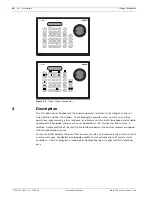
Page 13: ... LTC 8555 01 models use the Allegiant RS 485 communication protocol and are the most common versions These models are ready to operate as soon as they re connected to the Allegiant system The LTC 8555 02 and LTC 8555 03 are similar but use an RS 232 communication protocol These models can be used with communication links that support full duplex RS 232 transmission Since the RS 232 models connect ...

Page 14: ...an tilt equipped cameras are easily operated via the intuitive joystick control In addition simple rotation of the joystick knob allows operators to control cameras equipped with motorized zoom lenses Easy to read LED displays show real time camera monitor and communication status as well as error messages Keyboards also provide audible and visual indications of system alarm conditions A built in ...

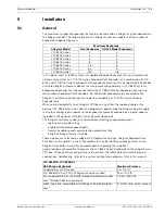
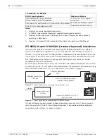
Page 15: ...ided via a power adapter included in the optional LTC 8557 Series Remote Hookup kit The Allegiant Switcher supports several options affecting keyboard operation login security mode setting enabled disabled keyboard ports fixed or variable speed communication protocol setting 4 digit or 6 digit Camera ID mode These options are selected via Allegiant CPU dipswitch settings Allegiant Keyboard User Fu...

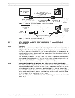
Page 16: ... data and power For connections beyond 30 m 100 ft the LTC 8557 Series Remote Hookup Kit can be used as shown in Figure 3 The LTC 8557 is also required when the keyboard is remoted over a long distance communication link such as a fiber optic system shown in Figure 4 Figure 5 1 Typical Configuration using supplied data power cable Figure 5 2 Typical Configuration using optional LTC 8558 00 cable T...

Page 17: ... of keyboards that can be connected to an Allegiant switcher When an RS 232 keyboard is connected in the system a standard keyboard port will automatically become disabled The disabled keyboard port number will be based on the interface connection type of the RS 232 keyboard Keeping track of these keyboard numbers is necessary when priority based restrictions or other keyboard related lockouts are...

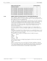
Page 18: ...of an Allegiant Console cable is recommended If necessary refer to the Allegiant Console cable pinout reference at the end of this manual The Allegiant RS 232 settings are user programmable but the default settings are Once online with the system an Allegiant prompt appears each time Enter is pressed The prompt will look as follows TC8x00 where x is a digit from one to nine varies based on the All...

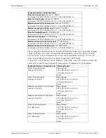
Page 19: ... connected to Printer port except LTC 8900 Command SET PORT RS232 4 4 8 0 1 1 _SET_KBD_MODE 4 1 Direct to Controller port LTC 8900 only Command SET PORT RS232 0 4 8 0 1 0 _SET_KBD_MODE 0 1 Direct to Console port LTC 8900 only Command SET PORT RS232 4 4 8 0 1 0 _SET_KBD_MODE 4 1 Modem connected to Controller port LTC 8900 only Command SET PORT RS232 0 4 8 0 1 1 _SET_KBD_MODE 0 1 Modem connected to ...

Page 20: ...re will follow in the operating instructions Figure 7 shows a typical system configuration using a modem connection Figure 5 6 Connection Using Dial up Modem Link Modem connected to Controller port LTC 8900 only Begin boot SET PORT RS232 0 4 8 0 1 1 _SET_KBD_MODE 0 1 break Modem connected to Console port LTC 8900 only Begin boot SET PORT RS232 4 4 8 0 1 1 _SET_KBD_MODE 4 1 break Keyboard interface...

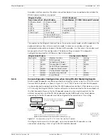
Page 21: ... Configuration using LTC 8712 Series Console Port Expander On Allegiant systems with a Printer port up to two Console Port Expanders can be connected supporting a total of eight RS 232 model keyboards Allegiant System RS 232 Keyboard 9 pin Console Port 25 pin Modem 25 pin Modem LTC 8557 Hookup kit Terminal 1 Chassis Gnd 1 Chassis Gnd 2 3 2 Rx 3 Tx 3 2 3 Tx 2 Rx 7 1 4 CTS 8 DCD Tie pin 4 RTS 5 RTS ...

Page 22: ...Expander mode Download the table into the Allegiant Set the internal dipswitches of the LTC 8712 Console Port Expander as follows Remember to power the Console Port Expander off on whenever any changes are made to its internal dipswitches Connect the data cable supplied with the LTC 8712 Console Port Expander between the unit and the appropriately configured port on the Allegiant For further detai...

Page 23: ...far and open or close the iris if the lens supports manual iris operations Up to three zoom lens functions can be sent simultaneously example Zoom Out using the joystick knob Focus Near and Iris Open 6 3 Numeric Keypad Use the numeric keypad when it s necessary to enter a numeric value for instance Camera numbers Monitor numbers user number or password information Leading zeros are not necessary w...

Page 24: ...ators requiring system access Perform the following steps to login to the keyboard 1 If the keyboard is displaying a camera and monitor number it is already logged on no action is required When the keyboard is in a logged off state the left side LEDs display 3 flashing dashes 2 Press ON A U should appear in the LED display as a prompt for entering a User number 3 Enter your User number via the num...

Page 25: ...board Operating Instructions 7 5 1 Camera Selection In default mode enter a valid 1 to 4 digit camera number using the numeric keypad and press ENTER If the Allegiant is configured to operate in 6 digit Camera ID mode up to 6 digits can be entered If the new camera is at the same site as the current camera simply enter 1 to 4 camera number digits If the desired camera is at a different site 5 or 6...

Page 26: ...our by pressing SET the digit 9 followed by the 2 digit pre position number Information supplied with the device will identify whether this feature is available 7 5 6 Recalling a Camera Pre position Scene Select the camera to be activated and press SHOT then enter a previously stored camera scene number via the numeric keypad and press ENTER The camera automatically returns to the previously store...

Page 27: ...changed via the optional Allegiant PC based Master Control Software package In cases where the alarm number does not match the camera number it is important to specify the alarm number when using this command The monitor status display if enabled shows CA camera alarm armed whenever an armed camera is selected 7 5 9 Arm Disarm All Alarms To arm disarm all alarms on the monitor currently controlled...

Page 28: ... is also possible to manually step though a stopped sequence either forward or reverse These actions work as follows If NEXT is pressed with the sequence in the stop state the sequence switches forward and remains stopped If the sequence is running when NEXT is pressed it immediately goes to the next step and continues to run The same is true for PREV but in the reverse direction If either NEXT or...

Page 29: ... is necessary If not enter the desired monitor number via the keypad and press ENTER Move RIGHT again The prompts now shift over to the dwell time shown above as D02 The default dwell time for a new sequence is two seconds If a different dwell period for this step is desired change the value to any number between 1 and 60 One line is now complete Press NEXT to add a second line The camera number a...

Page 30: ...group To program a salvo sequence enter the programming mode as described above for a simple camera sequence Since a salvo sequence involves multiple monitors switching as a group the sequence must involve more than 1 monitor An example of a simple salvo sequence that switches cameras on three monitors simultaneously is shown below in spreadsheet format In general follow the instructions used for ...

Page 31: ...IGURATION TABLE PRINTOUT 1 14 NOT USED 1 15 SYSTEM RESET 12 16 ENABLE TIMED EVENTS 1 17 SET MONITOR TITLE 1 18 SEQUENCE PRINTOUT 1 19 ALARM RESPONSE SELECTION 12 20 SELECT PRINTING MODE 1 21 DESIGNATE MONITOR TYPE 12 22 SELECT AutoDome SPEED TYPE 12 23 DISPLAY CPU VERSION NUMBER Any 24 ALL MONITOR DISPLAY POSITION 1 71 25 ALL MONITOR DISPLAY BRIGHTNESS 1 71 26 ALL MONITOR DISPLAY ON OFF 1 71 27 SE...

Page 32: ... For example if an attempt is made to access a monitor or controllable camera which has been locked by a higher priority operator the camera number is temporarily replaced with an appropriate error number then the number of the operator who placed the lock is briefly displayed Refer to the Installation manual supplied with the Allegiant system for a complete listing of error messages applicable to...

Page 33: ... 1 Supply voltage1 2 Gnd 3 Data 4 Data 5 Gnd 6 Supply voltage1 Supplied 6 Pin Data Power Cable Replacement part number 303 0239 001 Side Connection Side 1 Supply voltage1 6 2 Gnd 5 3 Data 4 4 Data 3 5 Gnd 2 6 Supply voltage1 1 Allegiant Console Cable Pinouts part number LTC 8506 00 Allegiant Side Console Port PC Side Serial Port Pin Connection Pin Connection 1 No connection 2 Rx 3 Tx 3 Tx 2 Rx 4 C...

Page 34: ...isplaying Flashing dashes If the login feature is enabled the keyboard may be logged off User LED lit and OFF LED lit If the login feature is not enabled or the keyboard port is logged in there is likely a data communication error Test the keyboard cable in another keyboard port Swap the suspect keyboard with a known good keyboard Try another keyboard data cable Check keyboard data cable connectio...

Page 35: ...ra and Monitor numbers being displayed but Allegiant systems will not respond to changes or PTZ controls Verify that the attempted function is applicable to the device being controlled or the switcher s current situation If using a directly connected cable the keyboard port or keyboard could be defective Swap the suspect keyboard with a known good keyboard If using a communication link other than ...

Page 36: ...ck 005 Monitor 008 Shot 009 Digit 1 010 Digit 4 011 Digit 7 012 Digit 0 013 Star 016 On 017 Digit 2 018 Digit 5 019 Digit 8 020 Camera 024 Off 025 KEY VALUE Digit 3 026 Digit 6 027 Digit 9 028 Enter 029 Seq 032 Run 033 Next 034 Prev 035 Hold 036 Clear 037 Focus high 042 Focus low 043 Iris high 045 Iris low 046 Down x50 Right x51 Up x52 Left x53 User enter exit ...

Page 37: ...anslator Chart Applies to LTC 8555 01 and LTC 8555 03 keyboard models The following chart is used to cross reference the text descriptions contained in the manual with the icons found on keyboard models LTC 8555 01 and LTC 8555 03 Ack Alarm Camera Clear Enter Focus Hold Iris Lock Monitor Next Off On Prev Prog Run Seq Set Shot User ...

Page 38: ...34 en Icon Translator Chart Allegiant Keyboards F 01U 127 290 2 0 2009 03 Instruction Manual Bosch Security Systems Inc ...

Page 39: ......

Page 40: ...curity Systems B V P O Box 80002 5600 JB Eindhoven The Netherlands Phone 31 40 2577 284 Fax 31 40 2577 330 emea securitysystems bosch com www boschsecurity com Asia Pacific Bosch Security Systems Pte Ltd 38C Jalan Pemimpin Singapore 577180 Phone 65 6319 3450 Fax 65 6319 3499 apr securitysystems bosch com www boschsecurity com Bosch Security Systems Inc 2009 F 01U 127 290 2 0 2009 03 Data subject t...

Reviews: