Setting the Sensor Type:
This module can be programmed to output the air/fuel ratio in the following units.
Lambda (fuel independent)
AFR for gasoline
AFR for methanol
Custom units (use for fuels not listed)
To change the output units, left click on the drop down arrow button next the the box labeled ‘Sensor’ then make
your selections. If you select the ‘A/F Units, Custom’ sensor type for a fuel other than gasoline or methanol, you
will need to enter the fuels stochiometric air fuel ratio value in the ‘Raw data value B’ ‘will become’ box. You will
also need to enter the minimum and maximum result values. When you have fishished making all changes you must
send the updated configuration to the module by following the instructions in the
Sending the Configuration to the
module
section below.
Setting the Sample Rates
The factory default sample rate is set to the maximum of 50 samples per second. If you wish to lower the sample
rate to attain longer recording times, simply change the ‘V_Net Update Rate’ and ‘Logger Sample Rate’ to the
disired value. The ‘V_Net Update Rate’ should be set to value which is equal to or greater than the ‘Logger Sample
Rate’.
When you have fishished making all changes you must send the updated configuration to the module by
following the instructions in the
Sending the Configuration to the module
section below.
Setting the Channel Mode
If you are not going to use a sensor with one of the channels, for instance you have a four channel controller but are
using only three sensors, you should set the channel mode for the unused channel to
Disabled
. If you do not
disable the channel the LED indicator on the control box will flash an error indicating the sensor heater is not
present. When a channel is disabled the LED indicator on the control box will ignore all errors on that channel.
Also, the recorded data will display a error code value of –0.17 to indicate the channel is disabled.
Sending the Configuration to the module:
When you have finished editing the configuration on your PC, you will need to send
the information to the sensor module. Be sure the serial interface cable is connected
to your data logger and power is applied to the system. To send the information
position the mouse cursor over the
Send Configuration
button and click the left
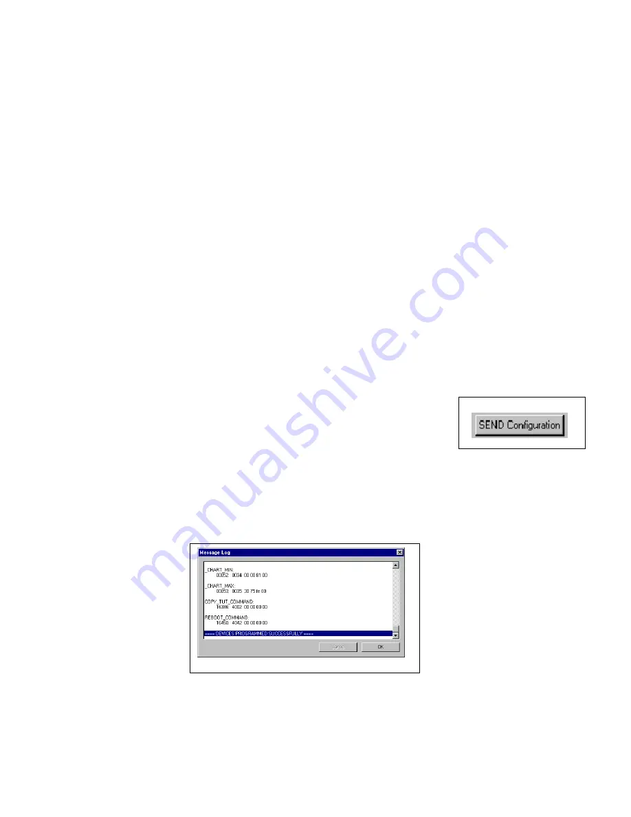
mouse button. The progress box as shown below will be displayed.
When finished sending the message “
Device Programmed Successfully
” should be displayed at the bottom of the
progress box. If you receive an error message, turn power to the system off and then back on and repeat the send
configuration process. If problems persist contact RacePak.
Save the configuration file to disk and update the Module Configuration Setup Box on the front of this worksheet
with the new setup configuration.


