


FCS-320-TM Aspirating Smoke Detector
Planning | en
43
Bosch Sicherheitssysteme GmbH
Operation Guide
F.01U.130.928 | 1.0 | 2009.11
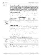
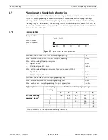
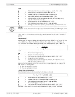
I pipe system activation thresholds
Example:
If 2 of a total of 5 air sampling openings are found to be obstructed, airflow monitoring must
be set to ± 20% using the FAS-ASD-DIAG Diagnostic Software.
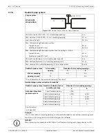
3.7.2
U-pipe system
I-pipe system
Number of obstructed air
sampling openings
Number of air sampling openings
2
3
4
5
Activation threshold
1 obstructed opening
± 30%
± 20%
± 15%
± 10%
2 obstructed openings
0
0
± 30%
± 20%
3 obstructed openings
0
0
0
0
4 obstructed openings
0
0
0
0
5 obstructed openings
0
0
0
0
0 not practical
NOTICE!
When planning in accordance with EN 54-20, airflow monitoring must always be set to 20%.
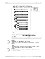
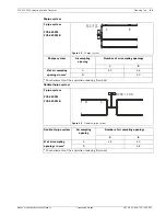
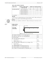
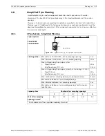
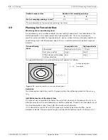
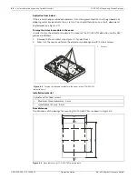
1 pipe system
FCS-320-TM
FCS-320-TM-R
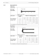
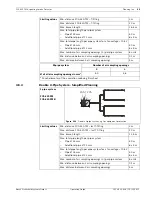
Figure 3.8
U-pipe system for space protection
Min. distance FCS-320-TM – 1st air sampling opening
2 m
Max. distance FCS-320-TM – 1st air sampling opening
20 m
max. branch length
25 m
Max. total pipe length per pipe system
–
Pipe Ø 25 mm
50 m
–
Additional pipe Ø 12 mm
8 x 3 m
Max. total pipe length per pipe system for a fan voltage < 10.5 V
–
Pipe Ø 25 mm
40 m
–
Additional pipe Ø 12 mm
8 x 3 m
Min. distance between 2 air sampling openings (d)
4 m
Max. distance between 2 air sampling openings (d)
10 m
Max. number of air sampling openings (n) per pipe system
8 units
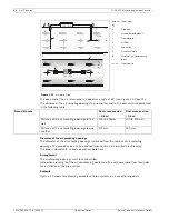
A
B
C
D
FAS / FCS
Summary of Contents for FCS-320-TM
Page 1: ...FCS 320 TM Aspirating Smoke Detector FCS 320 TM FCS 320 TM R en Operation Guide ...
Page 2: ......
Page 99: ......


