


24
en | Technical Specifications
FCS-320-TM Aspirating Smoke Detector
F.01U.130.928 | 1.0 | 2009.11
Operation Guide
Bosch Sicherheitssysteme GmbH
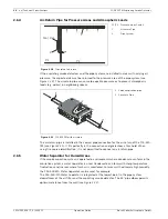
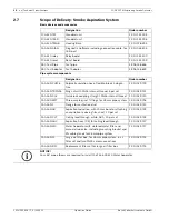
2.6.4
Air-Return Pipe for Pressure Areas and Atmospheric Loads
If the aspirating smoke detectors and the pipe system are installed in areas with varying air
pressure, the aspirated air must be returned to the pressure area of the pipe system (see
Figure 2.20
). The air-return pipe can serve to equalize pressure or to prevent atmospheric
loads (e.g. odors) in neighboring spaces.
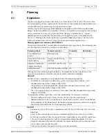
The air-return pipe is installed in the conical pipe connection for the air return of the FCS-320-
TM (see
Figure 2.21
). It fits perfectly in the connection and guarantees a firm hold. When
using fire source identification, it is not permitted to connect an air-return pipe.
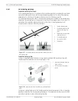
2.6.5
Water Separator for Humid Areas
If the smoke aspiration system is operated in environments where condensate can form in the
aspiration system, a water separator is used. Condensate can form with sharp temperature
fluctuations and in areas where fresh air is monitored. For areas with extremely high humidity,
the FAS-ASD-WS Water Separator can be used, for example.
The FAS-ASD-WS Water Separator is integrated at the lowest point in the pipe system
downstream of the air filter and the aspirating smoke detector. The 45° pipe elbow permits
optimum distance from the wall (see
Figure 2.22
).
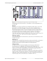
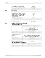
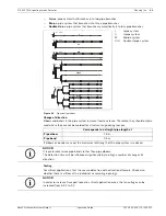
Figure 2.20
Principle of air return
P1/P2
Pressure areas 1 and 2
1
Air-return Pipe
2
Pipe System
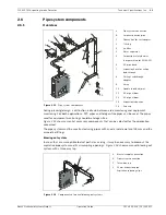
Figure 2.21
FCS-320-TM with air return
1
Smoke aspiration pipe
2
Air-return Pipe
2
FAS / FCS
1
P1
P2
FA
S-4
20
-TM
seri
es
2
1
Summary of Contents for FCS-320-TM
Page 1: ...FCS 320 TM Aspirating Smoke Detector FCS 320 TM FCS 320 TM R en Operation Guide ...
Page 2: ......
Page 99: ......


