


ATM/POS Bridge
Installation | en
13
Bosch Security Systems, Inc.
Installation Manual
F.01U.171.816 | 1.0 | 2010.09
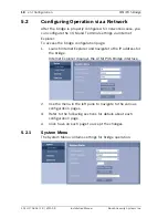
1.
Connect the supplied DC power adapter unit to the DC
power input connector of the bridge.
2.
Connect the RJ45 connector of the bridge via a straight
Ethernet CAT5 network cable to a network switch or hub
that supports 10BaseT.
3.
Connect your terminal to COM ports 1, 2, 3, or 4 of the
bridge using the supplied cable. Refer to
Section 4.3 COM
Connector Detail, page 14
for pin-out details.
Note: Choose COM port 4 on the bridge if your connection
protocol is RS485.
4.
Use the supplied splitter cable if the terminal device is also
connected to a printer.
a.
Remove the existing cable that connects the terminal
to a printer.
b.
Using the splitter cable, connect one male connector
to the terminal.
c.
Connect the other male connector to the printer.
d.
Connect the cable from the bridge to the open
connector on the splitter cable.
5.
Refer to
Section 5 Configuration, page 15
to configure the
communication and terminal settings.
Summary of Contents for DVRXEAP01
Page 1: ...ATM POS Bridge DVRXEAP01 en Installation Manual ...
Page 2: ......
Page 42: ...42 en ATM POS Bridge F 01U 171 816 1 0 2010 09 Installation Manual Bosch Security Systems Inc ...
Page 43: ......
Page 44: ...Bosch Security Systems Inc www boschsecurity com Bosch Security Systems Inc 2010 ...


