background image

Conettix DX4020 

|


Installation Guide | 6.0 IP Address Programming 


14 

Bosch Security Systems, Inc. | 1/09 | F01U045288-05


24.


Press [Enter] to accept CC as the default 
ConnectMode. If CC is not the default, type 

cc


and press [Enter] to change it. 


25.


Enter the appropriate Datagram value based on the 
type of control panel. Refer to 

Table 6


Table 6: 

Entering Datagram Values 


Control Panel Type 

Do Step: 

DS7240V2/DS7220V2 

25a 

FPD-7024 

25a 

D9412GV2/D7412GV2/D7212GV2 with 
firmware version 7.06 or later 

25a 

D9412G/D7412G with firmware version 7.00 
or later 

25a 

D7212G with firmware version 7.01 or later 

25a 

D9412/D7412/D7212/D9112/D9124 with 
firmware version 7.00 or later 

25a 

Easy Series with firmware version 3.0 or later 

25a 

DS7 

25b 

D9412GV2/D7412GV2/D7212GV2 with 
firmware version 7.05 or earlier 

25b 

D9412G/D7412G with firmware version 6.90 
or earlier 

25b 

D7212G with firmware version 6.91 or earlier 

25b 

D9412/D7412/D7212/D9112/D9124 with 
firmware version 6.90 or earlier 

25b 


a.


Type 

02

 and go to 

Step 28


Datagram 02 on the 9000, G, or GV2 
Series control panels requires RPS version 
5.5 or later. 


b.


If the unique port number previously entered 
is the same as the D6680 or D6100i, type

 00 

and go to 

Step 28

. Otherwise, type 

07

 and go to 

Step 26


To use Datagram 02 or 07, you must have 
Bosch firmware version 1.5d or later in the 
XPort Module. Public versions of the 
Lantronix firmware, including version 1.8, 
are not compatible with these datagrams. 
Refer to the 

DeviceInstaller Operation and 

Installation Guide

 (P/N: 4998138688) for 

more information. 

Refer to the

 Conettix D6600 System Guide


(P/N: 4998122712) for more information 
on datagram types. 


26.


Press [Enter] four times to specify 0.0.0.0 for 
remote IP address. 

27.


Enter the same port number used for the 
D6680/D6682 or D6100i. 

28.


To enable encryption, select 

6- Security

 from the 

Main Menu and follow 

Steps 29

 through 

33


If encryption is enabled on the DX4020 it 
must be enabled at the D6680/D6682 or 
D6100i-E120 with the same key. 

The software revision of the NIM attached 
to the DX4020 must be 1.5d or later. 
Check the version by starting a Telnet 
session with the unit and allowing the 
version to appear for 5 sec before pressing 
[Enter]. 


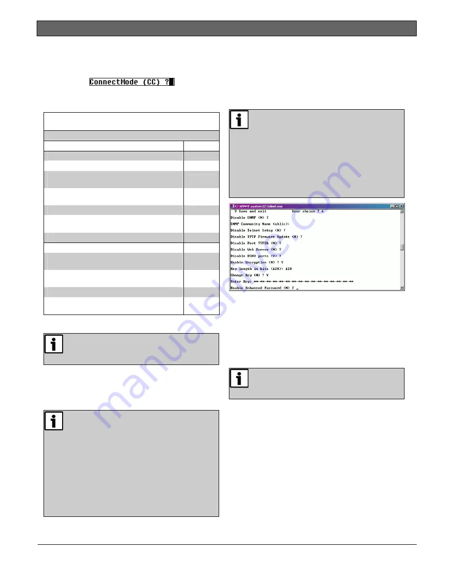
29.


Press [Enter] after the each of the following 
prompts: 

-


Disable SNMP (N) N


-


Disable SNMP Community Name (  ):


-


Disable Telnet Setup (N) N


-


Disable Port 77FEh (N) N


Disabling both the telnet and port 77FE 
prevents you from accessing the set-up 
menu for future changes. 


-


Disable Web Server (N) N


-


Disable ECHO ports (Y) Y


30.


At Enable Encryption (N), press [Y

]

31.


At Key length in bits (0), type 128 and press 
[Enter]. 

32.


At Change keys (N), press [Y]. 

33.


Enter the bytes programmed in the D6680. These 
16 bytes (32 characters) should match. The default 
value is 01-02-03-04-05-06-07-08-09-10-11-12-13-
14-15-16. 

34.


At Enable Enhanced Password (N), press [Enter]. 

Summary of Contents for Conettix DX4020

Page 1: ...EN Installation Guide Network Interface Module Conettix DX4020 ...

Page 2: ...ls 7 4 3 DS7400Xi Control Panel 8 4 4 FPD 7024 Control Panel 8 5 0 LEDs 8 5 1 Ethernet and Serial 8 5 2 XPort 9 6 0 IP Address Programming 9 6 1 Factory Programmed IP Configuration 9 6 2 Identifying the MAC Hardware Address 9 6 3 Obtaining an IP Address 9 6 4 Assigning the Initial IP Address 10 6 4 1 ARP Command Overview 10 6 4 2 Using the ARP Command 10 6 5 Using Telnet to Complete Configuration ...

Page 3: ... panels require Firmware Version 6 9 or higher GV2 Series control panels require Version 7 04 or later 2 Install the system according to NFPA 72 2 Add a Telnet password to the DX4020 communications protocol To complete the configuration refer to Section 6 5 Using Telnet to Complete Configuration page 11 Keep your password for future reference Certifications and Approvals UL Standards UL294 Access ...

Page 4: ... installed tested or maintained devices Follow these instructions to avoid personal injury and damage to the equipment 2 0 Overview Refer to Figure 2 for general system connections The main components are Compatible control panel Conettix DX4020 Ethernet Network Interface Module Conettix D6600 Communications Receiver Gateway Conettix D6680 Ethernet Network Adapter Conettix D6100i Communications Re...

Page 5: ... control panel documentation for complete installation instructions Figure 3 Mounting Holes 1 1 Mounting holes 3 Use an AE1 or AE2 Enclosure when mounting the DX4020 in a separate enclosure Ensure that all external wiring between and originating from the enclosures is in a metal conduit no longer than 6 m 20 ft 3 2 Wiring Run the wiring connections from the DX4020 data bus terminals to the compati...

Page 6: ...ts of the Local Authority Having Jurisdiction National Fire ProtectionAssociation Batterymarch Park Quincy MA 02269 Printed information describing proper installation operation testing maintenance evacuation planning and repair service is to be provided with this equipment D9412G Control Communicator is UL Listed For Central Station Local Remote Station and Household Fire Alarm and Central Station...

Page 7: ...er Use SDI Bus Address 80 Figure 6 with the DX4020 and PC9000 Use SDI Bus Address 88 Figure 7 with the DX4020 and RPS or for network communication Figure 6 DIP Switch Setting for Address 80 1 2 3 4 5 6 7 8 1 2 1 ON down 2 OFF up Figure 7 DIP Switch Setting for Address 88 1 2 3 4 5 6 7 8 1 2 1 ON down 2 OFF up 4 2 DS7240V2 DS7220V2 and Easy Series V3 ICP EZM2 Control Panels For proper network commu...

Page 8: ...tion Bus Address 250 Figure 11 when using the DX4020 with an FPD 7024 Control Panel Figure 11 DIP Switch Setting for Address 250 1 2 3 4 5 6 7 8 1 2 1 ON down 2 OFF up 5 0 LEDs 5 1 Ethernet and Serial Figure 12 and in Table 3 identify and describe the DX4020 s four bus and serial status LEDs Use the P2 jumper to enable jumper on or disable jumper off LED operation Figure 12 Ethernet and Serial LED...

Page 9: ...he network through the DX4020 If using RPS proceed to Section 6 1 Factory Programmed IP Configuration 6 1 Factory Programmed IP Configuration The DX4020 is shipped with the following default IP settings Default IP Configuration Number DHCP Default Port 7700 Default DHCP Device Name Cxxxxxx xxxxxx last six digits of the MAC address 6 2 Identifying the MAC Hardware Address The MAC address is hard co...

Page 10: ...IP address assigned to the DX4020 by the network administrator 2 zz zz zz zz zz zz The MAC hardware address on the DX4020 XPort NIM Section 6 4 2 describes how to assign an IP address to a DX4020 NIM using the ARP command 6 4 2 Using the ARP Command 1 From the Start Menu select Start Æ Run to open a DOS window 2 At the Run dialog box type COMMAND and click OK A DOS window appears 1 At the DOS comm...

Page 11: ...ct Connect Æ Remote System The Connect window opens 4 At the Host Name field type the DX4020 IP address assigned in the previous section In this example the IP address is 172 17 10 70 5 At the Port field type 1 and leave the TermType field at vt100 6 Click Connect and wait a few seconds for the following failed message to appear 7 Click OK to open the Telnet window again 8 Repeat Step 3 in Section...

Page 12: ...3 Press 1 9 0 2 0 0 1 2 8 2 1 9 Enter to program IP Address 190 200 128 219 14 When using DHCP press 0 0 0 0 Enter 15 When prompted to set the Gateway address If the Gateway address is not required or if using DHCP type N and press Enter If the Gateway address is required type Y and the Gateway IP address 190 200 128 1 Then press Enter The Gateway IP is required only when using a WAN In a LAN the ...

Page 13: ...ng the DX4020 to communicate to RPS over a network enter a unique name known to the person programming the control panel If you do not enter a DHCP device name the default Cxxxxxx is used where xxxxxx is the last six digits of the MAC address 18 Change the Telnet password by pressing Y and entering a password or press Enter to leave the default telnet password This screen shows the Setup Mode scre...

Page 14: ...sion 1 5d or later in the XPort Module Public versions of the Lantronix firmware including version 1 8 are not compatible with these datagrams Refer to the DeviceInstaller Operation and Installation Guide P N 4998138688 for more information Refer to the Conettix D6600 System Guide P N 4998122712 for more information on datagram types 26 Press Enter four times to specify 0 0 0 0 for remote IP addre...

Page 15: ...dows 2000 or XP with an administrator privilege level The following example uses the IP address of 172 17 10 70 and the MAC Address of 00 20 4a 72 04 0e 1 At the Start Menu select Start Æ Run to open a DOS window 2 At the Run dialog box type COMMAND and click OK A command prompt window appears 3 At the C prompt type telnet and press Enter 4 At the Microsoft Telnet prompt type open space IP ADRESS ...

Page 16: ...elease Notes P N 4998154793 FPD 7024 FPD 7024 Operation and Installation Guide P N F01U008458 Easy Series V3 Easy Series System Reference Guide P N F01U087835 8 0 Specifications Table 8 Specifications Dimensions 7 6 cm x 12 7 cm 3 in x 5 in Current Draw 110 mA maximum 10 Base T 135 mA maximum 100 Base T Operating Voltage 12 VDC nominal Connectors Control Panel Option or data bus terminal strip LAN...

Page 17: ...Conettix DX4020 Installation Guide 8 0 Specifications Bosch Security Systems Inc 1 09 F01U045288 05 17 Notes ...

Page 18: ... 2009 Bosch Security Systems F01U045288 05 Bosch Security Systems Inc 130 Perinton Parkway Fairport NY 14450 9199 800 289 0096 ...

Reviews: