


32
en | Installing the Pendant Arm Wall, Corner, and Mast (Pole) Mounts
AUTODOME IP starlight 7000i
2021-03 | 1.2 |
Installation Manual
Bosch Security Systems
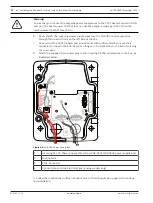
!
Warning!
Ensure that you connect the outgoing power supply wires to the P107 heater connectors (HN
and HL). The heater power (XF103) fuse can handle a higher amperage (3.15 A) than the
camera power (XF102) fuse (2.0 A).
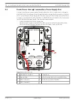
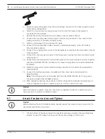
6.
Route the 24 VAC outgoing power supply wires into the VG4-PA0 power supply box
through the conduit fitting on the left side of the box.
7.
Cut and trim the 24 VAC power and ground wires with sufficient slack to reach their
connector terminal in the box, but not so long as to be pinched by or to obstruct closing
the cover door.
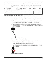
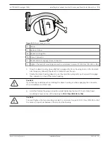
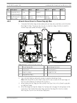
8.
Attach the supplied 3-pin power plug to the incoming 24 VAC power wires in the box, as
illustrated below.
GND TXD RXD
C+ C-
GND TXD RXD
C+ C-
P101
1 2 3
6 5 4 3 2 1
6 5 4
5 4 3 2 1
6 5 4
5 4
5 4
6 5 4
5 4
6 5 4
5 4
5 4
6 5 4
6 5 4
6 5 4 3 2 1
3 2 1
6 5 4 3 2
5 4 3 2
3 2
5 4 3 2
P106
P105
P10
7
XF
10
2
XF
10
3
XF
10
1
5
4
3
2
1
J1
03
J1
03
J1
03
J102
J101
(LED)
HTR DOME
XD
(FUSE)
(FUSE)
(FUSE)
24V NC 24V
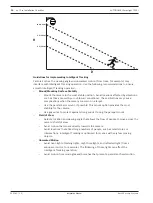
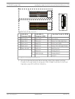
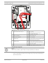
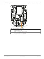
Figure 9.6:
VG4-PA0 Power Supply Box
1
Incoming 24 VAC Power Supply Wires (from VG4-PSU1/VG4-PSU2 power supply box)
2
Ground Wire
3
P101 Connector
4
Control Data and Video In/Out Wires (analog models only)
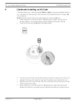
9. Follow the instructions in
Attach Pendant Arm to Power Supply Box, page 33 to continue
the installation.
Summary of Contents for AUTODOME IP starlight 7000i NDP?7512?Z30
Page 1: ...AUTODOME IP starlight 7000i NDP 7512 Z30 NDP 7512 Z30K en Installation Manual ...
Page 2: ......
Page 71: ......


