


OMD10078 rev F
53
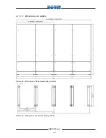
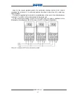
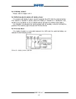
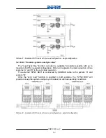
Picture 41 – Example of UPS units in Sync-Load configuration – single configuration
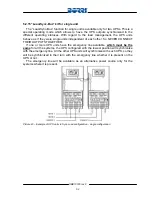
5.2.16 Kit “Parallel system Load-Sync-Bus”
The “Load Sync Bus” function can also be available for parallel systems with up to
maximum 6 UPS in parallel configuration. Picture 43 explains the interconnection of two
systems “A” and “B” in the sync load operation .
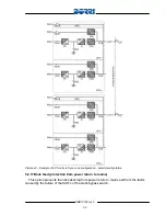
The external “SYNC BOX” is connected by CANBUS cable to the system “A” and
system “B”.
After the “sync load” function is enabled in both systems, the “SYNC BOX” will
provide to keep the systems output synchronised on various operating conditions.
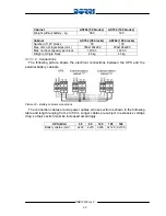
Picture 42 – Example of UPS units in Sync-Load configuration – parallel configuration