Installation and start-up of UPS B9000FXS
Installazione e avviamento B9000FXS
24
OMD10081 REV. I
The electrical connection is part of the work which is normally provided by the company that
carries out the electrical installation and not by the UPS manufacturer. For this reason, the
following recommendations are only an indication, as the UPS manufacturer is not responsible
for the electrical installation. In any case we recommend to carry out the installation and the
electrical input and output connections in compliance with the local standards.
Cables must be selected bearing in mind technical, financial and safety aspects. The
selection and the sizing of cables from a technical viewpoint depend on the voltage, on the
current absorbed by the UPS, on the bypass line and on the batteries, on the ambient
temperature and on the voltage drop. Finally, the kind of cable laying must be taken into
particular consideration.
For more explanations regarding the selection and the sizing of cables, please refer to the
relevant IEC standards, in particular to IEC 64-8 standard.
“Short-circuit currents” (very high currents with a short duration) and “overload currents”
(relatively high currents with a long duration) are among the main causes of cable damage. The
protection systems normally used to protect the cables are: thermal magnetic circuit breakers or
fuses. Protection circuit breakers must be selected according to the maximum short-circuit
current (max Isc) that is needed to determine the breaking power of automatic circuit breakers,
and to the minimum current (min Isc) that is needed to determine the maximum length of the
line protected. The protection against short-circuit must operate on the line before any thermal
and electrothermal effects of the overcurrents may damage the cable and relevant connections.
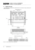
During the electrical installation take particular care to respect the phase rotation. The
terminal boards for cables connection are positioned at the front of the UPS, under the
breakers. To access the terminals remove the front protection, extracting the fixing bolts.
Mains connection
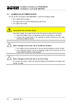
The connection to the mains must be carried out with protection fuses between the
mains and the UPS.
The use of differential protection devices in the line supplying the UPS is
unadvisable. The leakage current to ground due to the RFI filters is rather high
and it can cause spurious tripping of the protection device.
According to CEI EN62040-1 standard, in order to take into account the UPS’
leakage current, residual current devices having adjustable threshold can be used.
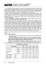
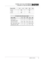
Electrical connection data
Power (kVA)
60 80 100 125 160
Input Fuses (A)
Rectifier
3x125 3x150 3x200 3x250 3x315
Bypass
3x150 3x200 3x315 3x315 3x400
Input cables
(mm
2
)
Rectifier
3x35 3x50 3x70 4x95 3x120
Bypass
4x35 4x50 4x70 4x95 4x120
Ground cables (mm
2
)
16 25 35 50 70
Output cables (mm
2
)
4x35 4x50 4x70 4x95 4x120
Battery cables
(mm
2
)
2x35 4x50 4x70 2x95 2x120
Summary of Contents for ASD10
Page 1: ...OPERATING MANUAL UPS MANUALE OPERATIVO UPS B9000FXS 60 80 100 125 160kVA ...
Page 2: ......
Page 5: ...Warnings and general information Avvertenze e informazioni generali 2 OMD10080 REV B ...
Page 96: ...UPS user manual Utilizzo dell UPS OMD10082 REV F 5 ENGLISH LANGUAGE ...
Page 142: ...UPS user manual Utilizzo dell UPS OMD10082 REV F 51 LINGUA ITALIANA ...

