background image

Installation and start-up of UPS B9000FXS 

Installazione e avviamento B9000FXS 


OMD10013 REV. I 

7


SAFETY RULES AND WARNINGS 

2.1 UPS 

USE 

Congratulations on choosing a product from Borri for the safety of your equipment. To obtain 

the best performance from your B9000FXS UPS system (Uninterruptible Power Supply), we 
suggest that you take your time to read the following manual. 

The purpose of this manual is to give a short description of the parts composing the UPS and 

to guide the installer or the user through the installation of the unit in its using environment.  

The installer or the user must read and correctly perform the instructions included in the 

present manual, with particular reference to the requirements regarding safety, in compliance 
with the current regulations. 


Read the technical documentation 


Before installing and using the device, make sure you have read and understood all 
the instructions contained in the present manual and in the technical supporting 
documentation. 


Summary of Contents for ASD10

Page 1: ...OPERATING MANUAL UPS MANUALE OPERATIVO UPS B9000FXS 60 80 100 125 160kVA ...

Page 2: ......

Page 3: ...4 13 02 15 E Biancucci F Berti E I 1 1 Codice Code OMD10079 OPERATING MANUAL UPS MANUALE OPERATIVO UPS Index of sections Indice delle sezioni Code Codice 1 WARNINGS AND GENERAL INFORMATION AVVERTENZE E INFORMAZIONI GENERALI OMD10080 2 INSTALLATION AND START UP OF UPS INSTALLAZIONE ED AVVIAMENTO OMD10081 3 UPS USER MANUAL UTILIZZO DELL UPS OMD10082 ...

Page 4: ... 20 05 13 E Biancucci F Berti E I 1 14 Codice Code OMD10080 WARNINGS AND GENERAL INFORMATION AVVERTENZE E INFORMAZIONI GENERALI Index Indice ENGLISH LANGUAGE 3 1 CONVENTIONS USED 4 2 DOCUMENTATION NOTES 5 3 CONTACTS 5 4 FACTORY WARRANTY 6 5 LIMITATION OF LIABILITY 8 LINGUA ITALIANA 9 1 CONVENZIONI UTILIZZATE 10 2 NOTE SULLA DOCUMENTAZIONE 11 3 CONTATTI 11 4 GARANZIA DI FABBRICA 12 5 LIMITAZIONE DI...

Page 5: ...Warnings and general information Avvertenze e informazioni generali 2 OMD10080 REV B ...

Page 6: ...Warnings and general information Avvertenze e informazioni generali OMD10080 REV B 3 ENGLISH LANGUAGE ...

Page 7: ...e risks to persons and property HAZARD HAZARD statements contain characteristics and basic instructions for the safety of persons Non compliance with such indications may cause serious injury or death WARNING WARNING statements contain characteristics and basic instructions for the safety of persons Non compliance with such indications may cause injury CAUTION CAUTION statements contain characteri...

Page 8: ...y exhaustive please contact the manufacturer of the device whose details are available in the Contacts section 3 CONTACTS For any information about the UPS systems manufactured by BORRI please contact Borri S p A Via 8 Marzo 2 52010 Soci Bibbiena AREZZO Tel 0575 5351 Fax 0575 561438 info borri it www borri it For help with technical problems or for information concerning device use and maintenance...

Page 9: ...l be charged to the end customer c In case of service performed following a call made by mistake or in case our technicians incur extra time and or costs due to the site inaccessibility or due to work interruptions required by the customer such costs will be invoiced in accordance with ANIE rates CLASS III COLUMN B Modes required a In the event of a fault covered by the warranty the customer shall...

Page 10: ...as dirt fire flooding failed operation of the air conditioning system etc Non compliance with applicable safety standards Force majeure e g lightning surges natural disasters fire acts of war riots etc Fall or displacement due to incorrect installation Ordinary wear caused by proper and continuous use of the device b Protective devices inside the units fuses and dischargers are also excluded from ...

Page 11: ...idered improper and therefore hazardous The manufacturer cannot be held responsible for possible damage arising from improper erroneous or unreasonable usage Borri assumes responsibility for the equipment in its original configuration Any intervention that alters the structure or the operating cycle of the equipment must be carried out and authorized directly by Borri Borri will not be held respon...

Page 12: ...Warnings and general information Avvertenze e informazioni generali OMD10080 REV B 9 LINGUA ITALIANA ...

Page 13: ...persone e cose PERICOLO Le indicazioni di PERICOLO riportano caratteristiche e istruzioni fondamentali per la sicurezza delle persone L inosservanza di tali indicazioni può causare lesioni gravi o morte AVVERTIMENTO Le indicazioni di AVVERTIMENTO riportano caratteristiche e istruzioni fondamentali per la sicurezza delle persone L inosservanza di tali indicazioni può causare lesioni ATTENZIONE Le i...

Page 14: ...urienti si prega di contattare il costruttore del dispositivo i cui dettagli sono disponibili alla sezione Contatti 3 CONTATTI Per qualsiasi informazione relativa ai gruppi statici di continuità prodotti da BORRI è possibile rivolgersi a Borri S p A Via 8 Marzo 2 52010 Soci Bibbiena AREZZO Tel 0575 5351 Fax 0575 561438 info borri it www borri it In caso di problemi tecnici o informazioni relative ...

Page 15: ...ranno riaddebitati al cliente finale f In caso di intervento in seguito ad una chiamata fatta per errore o nell eventualità in cui i nostri tecnici dovessero incorrere in tempo e o spese aggiuntive a causa di inaccessibilità del sito o sospensioni del lavoro richieste da parte del cliente tali oneri verranno fatturati in accordo alle tariffe ANIE CLASSE III COLONNA B Modalità richieste a In caso d...

Page 16: ...nzionamento dell impianto di condizionamento etc mancato rispetto delle norme di sicurezza pertinenti forza maggiore per es fulmini sovratensioni calamità naturali incendi atti di guerra sommosse etc cadute o spostamenti dovuti ad installazione non corretta normale usura causata da un uso proprio e continuativo dell apparecchio b Sono inoltre esclusi dalla garanzia i dispositivi di protezione inte...

Page 17: ...ltro uso è da considerarsi improprio e quindi pericoloso Il Costruttore non può essere considerato responsabile per eventuali danni causati da usi impropri erronei ed irragionevoli Borri si ritiene responsabile della macchina nella sua configurazione originale Qualsiasi intervento che alteri la struttura o il ciclo di funzionamento della macchina deve essere eseguito ed autorizzato direttamente da...

Page 18: ...dex Indice ENGLISH LANGUAGE 5 1 SCOPE 6 2 SAFETY RULES AND WARNINGS 7 2 1 UPS USE 7 2 2 B9000FXS RATING 8 2 3 SPECIAL SAFETY WARNINGS 9 2 3 1 General warnings 9 2 3 2 Personnel 9 2 3 3 Transport and handling 9 2 3 4 Installation 10 2 3 5 Electrical connection 11 2 3 6 Operation 12 2 3 7 Maintenance 13 2 3 8 Storage 14 2 4 ENVIRONMENTAL PROTECTION 14 2 4 1 ISO 14001 certification 14 2 4 2 Recycling...

Page 19: ...liary battery contact 30 4 4 4 Remote emergency power off EPO 30 4 5 SERIAL INTERFACES 31 4 6 RELAY CARD CONNECTION OPTIONAL 32 5 STARTUP AND SHUTDOWN 33 5 1 PRELIMINARY CHECKS 33 5 2 START UP PROCEDURE 34 5 3 BASIC TROUBLESHOOTING 35 5 4 SHUT DOWN PROCEDURE 36 5 5 SWITCHING PROCEDURE TO MANUAL BYPASS 37 5 6 RESTART FROM MANUAL BYPASS 38 LINGUA ITALIANA 40 1 APPLICABILITA 41 2 REGOLE E AVVERTENZE ...

Page 20: ...inime dalle pareti e ventilazione 55 3 3 4 Condizioni ambientali di installazione 56 4 ALLACCIAMENTO ELETTRICO 58 4 1 PROTEZIONE CONTRO IL RITORNO DI TENSIONE BACKFEED 60 4 2 MORSETTIERE 61 4 3 COLLEGAMENTO CONDUTTORI DI POTENZA 63 4 4 COLLEGAMENTO CAVI AUSILIARI 64 4 4 1 Manual bypass esterno 65 4 4 2 Generatore diesel DIESEL MODE 65 4 4 3 Contatto ausiliario batteria 65 4 4 4 Spegnimento remoto ...

Page 21: ...of B9000FXS 26 Picture 7 Position of auxiliary terminals of B9000FXS 29 Picture 8 Auxiliary terminals of B9000FXS 30 Picture 9 Interfaces of UPS B9000FXS 31 Picture 10 Relay card 32 Figura 1 Targhetta caratteristiche B9000FXS 43 Figura 2 Movimentazione UPS B9000FXS 51 Figura 3 Pianta di base 53 Figura 4 Ingombri UPS B9000FXS 54 Figura 5 Distanze minime dalle pareti 55 Figura 6 Posizione morsetti p...

Page 22: ...Installation and start up of UPS B9000FXS Installazione e avviamento B9000FXS OMD10013 REV I 5 ENGLISH LANGUAGE ...

Page 23: ...0FXS 80kVA ASD12 B9000FXS 100kVA ASD13 B9000FXS 125kVA ASD14 B9000FXS 160kVA Storing documentation This manual and any other supporting technical documentation relating to the product must be stored and made accessible to personnel in the immediate vicinity of the UPS Further information In the event that the information provided in this manual is not sufficiently exhaustive please contact the man...

Page 24: ... manual is to give a short description of the parts composing the UPS and to guide the installer or the user through the installation of the unit in its using environment The installer or the user must read and correctly perform the instructions included in the present manual with particular reference to the requirements regarding safety in compliance with the current regulations Read the technica...

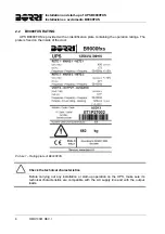
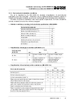
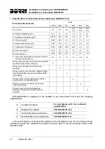
Page 25: ...an identification plate containing the operation ratings The plate is fixed on the inside of the door Picture 1 Rating plate of B9000FXS Check the technical characteristics Before carrying out any installation or start up operation on the UPS make sure its technical characteristics are compatible with the AC supply line and with the output loads ...

Page 26: ... qualification shall be considered as such only when certified by the manufacturer 2 3 3 Transport and handling Avoid bending or deforming the components and altering the insulation distances while transporting and handling the product Undistributed weight The weight of the UPS is not uniformly distributed Pay attention when lifting Please inspect the device before installing it In case any damage...

Page 27: ...e it near a source of heat Special environmental conditions UPS B9000FXS is designed for normal climatic and environmental operating conditions as defined in the technical specification altitude ambient operating temperature relative humidity and environmental transport and storage conditions It is necessary to implement specific protective measures in case of unusual conditions harmful smoke dust...

Page 28: ...cumentation The UPS must be installed according to the requirements of HD 384 4 42 S1 A2 and in compliance with standard CEI 60346 4 42 Before connecting the unit to the distribution network make sure you have received the approval of the electrical power distribution Authority so as provided for by the current national regulations IT system The UPS is also designed to be connected to an IT power ...

Page 29: ...long must comply with all the current safety standards technical equipment and accident prevention regulations The device can be started operated and disconnected only by authorized personnel The settings can only be changed using the original interface software Injury hazard due to electric shock During operation UPS B9000FXS converts power characterized by high voltages and currents All the door...

Page 30: ...e supply sources due to the internal capacitors which discharge slowly Thus we recommend to wait at least 5 minutes before opening the device doors Injury hazard due to electric shock Any operation must be carried out only when voltage is absent and in compliance with safety directives Make sure the battery circuit breaker that may be placed near the battery has been opened Isolate the device comp...

Page 31: ...uctive or radiant heat from other sources fungus insects vermin 2 4 ENVIRONMENTAL PROTECTION 2 4 1 ISO 14001 certification Borri is particularly sensitive to the environmental impact of its products That is why UPS B9000FXS has been manufactured with cutting edge eco design criteria ISO 14001 certification Special care was taken in using fully recyclable materials and in reducing the amounts of ra...

Page 32: ...lease use the original package Danger to persons due to transport damages Mechanical damage to the electrical components constitutes a serious danger to persons and property In case of doubt regarding the non integrity of the package or of the product contained therein contact the manufacturer before carrying out the installation and or the start up 3 1 1 Storage The package normally ensures prote...

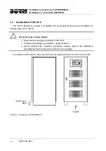
Page 33: ...or storage place via a fork lift The device has a heavy weight Avoid turnover during the transport of the UPS Cabinets must always be handled in upright position During loading and unloading operations always respect the indications regarding the device barycentre marked on the package To handle the UPS remove the lower front and rear panel and insert the forks of a fork lift Picture 2 Handling of...

Page 34: ... in the place of installation in compliance with the current legislation please refer to the Ventilation section Special environmental conditions It is necessary to implement specific protective measures in case of unusual environmental conditions harmful smoke dust abrasive dust humidity vapour salt air bad weather or dripping explosive dust and gas mixture extreme temperature variations bad vent...

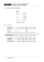
Page 35: ...Power kVA 60 80 100 125 160 L1 mm 815 P1 mm 825 L2 mm 70 The supporting base of the UPS must be designed to carry the UPS weight and to ensure its steady and safe support Its carrying capacity must be adequate to the static loads indicated in the table below Power kVA 60 80 100 125 160 Weight kg 570 600 630 662 720 Static load kg m2 948 998 1048 1101 1198 ...

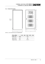
Page 36: ...art up of UPS B9000FXS Installazione e avviamento B9000FXS OMD10013 REV I 19 3 3 2 Overall dimensions Picture 4 Overall dimensions of UPS B9000FXS Power kVA 60 80 100 125 160 Width mm W 815 Depth mm D 825 Height mm H 1670 ...

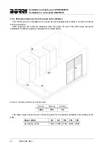
Page 37: ...ow a correct air flow as much as possible With regard to the minimum distances from the walls for all of the UPS sizes the same installation conditions apply as indicated in the table below Picture 5 Minimum distances from the walls A mm B mm D mm 1000 700 50 The table below shows the air volume required for an optimal ventilation and cooling of the UPS Power kVA 60 80 100 125 160 Air volume m3 h ...

Page 38: ...n rain NO Ice formation NO Classification of biological conditions EN 60721 3 3 Environmental parameter Class 3B1 3B2 3B3 a Flora NO Presence of mildew fungus etc Presence of mildew fungus etc b Fauna NO Presence of rodents and other animals that are harmful to products excluding termites Presence of rodents and other animals that are harmful to products including termites Classification of mechan...

Page 39: ...ted clean spaces category X Places where atmosphere is permanently monitored X Places located in rural and urban regions where industrial activities are few and where traffic is moderate X Places located in urban regions with industrial activities and or considerable traffic X Places in proximity to industrial sources with chemical emissions X Places located in industrial installations Emissions o...

Page 40: ...e electric connection must be carried out by qualified and trained personnel Work in compliance with the local standards The installation of UPS B9000FXS must be carried out in compliance with national and local regulations Connection of ground cable The grounding of the UPS via the relevant terminal is mandatory It is strongly recommended to connect the ground terminal as first terminal Check the...

Page 41: ...ion circuit breakers must be selected according to the maximum short circuit current max Isc that is needed to determine the breaking power of automatic circuit breakers and to the minimum current min Isc that is needed to determine the maximum length of the line protected The protection against short circuit must operate on the line before any thermal and electrothermal effects of the overcurrent...

Page 42: ...d back on the input terminals during the a mains failure The use of a device installed inside the UPS allows a higher flexibility of use as only the bypass line is cut leaving the rectifier battery charger in operation The use of an external device forces the user to separate the UPS supply lines rectifier and bypass if the flexibility and availability of the UPS are supposed to be kept unaltered ...

Page 43: ...0FXS Installazione e avviamento B9000FXS 26 OMD10081 REV I 4 2 TERMINAL BOARDS UPS B9000FXS is provided with terminal boards for the connection of power cables and of auxiliary connections Picture 6 Position of power terminals of B9000FXS ...

Page 44: ...wer kVA 60 80 100 125 160 X mm 270 260 Y mm 18 30 Z mm 598 615 Connection data of terminal boards Power kVA 60 80 100 125 160 Section mm2 35 35 70 25x6 30x5 Hole diameter mm 11 11 11 11 11 Cable terminal hole M6 M6 M8 M10 M10 Max cable section mm2 35 35 70 2x95 2x150 Tightening force Nm 5 5 10 15 20 ...

Page 45: ... from the battery Isolate the battery via DC circuit breakers before connecting it to the UPS Connect the ground cable to the relevant bar before carrying out any other connection inside the device Risk of damages to the device due to insufficient insulation The cables must be protected from short circuits and leakage currents to earth The connection points must be hermetically sealed to prevent t...

Page 46: ...rols components specifically designed to improve the safety and reliability of the device External manual bypass Diesel generator Auxiliary battery contact Remote emergency power off button EPO The auxiliary cables are connected using a special terminal board placed aligned with the power terminal boards The section of the terminals used is 6 mm2 Picture 7 Position of auxiliary terminals of B9000F...

Page 47: ...s to be connected to XD1 XD2 terminals when the contact is closed if diesel mode is enable the microprocessor will acquire the status of the contact and the rectifier will reduce the voltage to the value set 4 4 3 Auxiliary battery contact Aux battery contact on terminals BAC1 BAC2 This auxiliary contact is necessary to indicate the position of the isolator open closed and the fuse status 4 4 4 Re...

Page 48: ...tus and parameters RS232 USB is used for connection to the proprietary programming and control software MODBUS is used for the transmission of data to the outside via MODBUS protocol RS485 PARALLEL OPTIONAL is used for communication between paralleled UPS units SNMP OPTIONAL is used for the external transmission of data via LAN NORMAL BYPASS SELECTOR NORMAL SERVICE SELECTOR Picture 9 Interfaces of...

Page 49: ...General alarm Not energized 2 3 Open D1 Off 1 2 Closed RL2 Alarm Mains fault Not energized 5 6 Open D2 Off 4 5 Closed RL3 Alarm Battery low Not energized 8 9 Open D3 Off 7 8 Closed RL4 Alarm Inverter out of tolerance Not energized 11 12 Open D4 Off 10 11 Closed RL5 Alarm Bypass feeds load Not energized 14 15 Open D5 Off 13 14 Closed RL6 Status Booster OK Energized 17 18 Closed D6 On 16 17 Open RL7...

Page 50: ...anufacturer of the device whose details are available in the Contacts section 5 1 PRELIMINARY CHECKS Before starting up the unit make sure that all installation and electric connection works have been performed professionally all power and control cables have been properly and tightly connected to the relevant terminal boards the ground cable is properly connected the battery polarity is correct a...

Page 51: ...breaker RCB the pre charging phase of the capacitive bank will start The control logic will be started and the front panel will be activated 2 BOOT LOADING BOOT phase where the UPS firmware can be updated following the appropriate procedure All the LED s on the front panel are on 3 EEPROM READING Reading of the configuration parameters stored in the EEPROM All the LED s on the front panel are off ...

Page 52: ...the problem cannot be solved contact the service department 1 After closing RCB the LCD display is still blank Check the phase rotation of supply voltage Make sure the input voltage and frequency are within tolerance Check the rectifier protection fuses F1 F2 F3 they are inside the unit 2 After step 1 the UPS stops the starting sequence and shows one or more alarm messages Check the alarms indicat...

Page 53: ...NG CHECKS 1 Open OCB A30 GENERAL ALARM The supply to the load is interrupted LED 7 off 2 Open BCB A30 GENERAL ALARM The battery is disconnected from the rectifier Led 4 red flashing 3 Open SBCB A30 GENERAL ALARM The bypass supply is disconnected LED 2 off 4 Open RCB A30 GENERAL ALARM Rectifier and inverter shutdown 5 BLANK End of shutdown procedure ...

Page 54: ...ON LCD DISPLAY OPERATING CHECKS 1 Move the bypass selector SW to BYPASS A30 GENERAL ALARM The load is transferred to the bypass line LED 5 off LED 6 lit orange 2 Close MBCB A30 GENERAL ALARM The inverter is switched off The load is supplied by the input mains through the manual bypass switch The static bypass switch is still closed Led 8 lit orange 3 Open BCB A30 GENERAL ALARM The battery is disco...

Page 55: ...ront panel are on The microprocessor checks that all the start up conditions are good for restart Led 1 lit green Led 8 lit orange 5 RECTIFIER START UP WAIT PLEASE The IGBT rectifier bridge starts to modulate VDC voltage reaches the nominal value LED 3 is lit green DC voltage present 6 START UP FROM MBCB CLOSE BCB Close SBCB 7 BYPASS START UP WAIT PLEASE The microprocessor checks that all the bypa...

Page 56: ...hes the nominal value The microprocessor checks the synchronization with the bypass line 12 START UP FROM MBCB MOVE BYP SWITCH Move the selector NORMAL BYPASS to NORMAL The load is transferred to the inverter Led 5 lit green 13 START UP END WAIT PLEASE The microprocessor checks that all the output parameters voltage current frequency are within the tolerance limits 14 UPS MODEL OUTPUT VOLTAGE ...

Page 57: ...Installation and start up of UPS B9000FXS Installazione e avviamento B9000FXS 40 OMD10081 REV I LINGUA ITALIANA ...

Page 58: ...2 B9000FXS 100kVA ASD13 B9000FXS 125kVA ASD14 B9000FXS 160kVA Conservazione della documentazione Questo manuale e tutta la restante documentazione tecnica di supporto al prodotto devono essere conservati e possibilmente resi accessibili al personale nelle immediate vicinanze dell UPS Informazioni aggiuntive Nel caso le informazioni riportate nel presente manuale non fossero abbastanza esaurienti s...

Page 59: ... Lo scopo di questo manuale è di descrivere brevemente le parti che compongono l UPS e di guidare l installatore o l utente ad una corretta installazione dell apparato nell ambiente di utilizzo L installatore o l utente dovrà leggere ed eseguire correttamente quanto dichiarato nel presente manuale con particolare riguardo alle richieste relative alla sicurezza in accordo alle normative in vigore L...

Page 60: ... che riporta i dati nominali di funzionamento La targhetta è fissata nel lato interno della porta Figura 1 Targhetta caratteristiche B9000FXS Verificare le caratteristiche tecniche Prima di effettuare qualsiasi operazione di installazione e avviamento del dispositivo verificare che le caratteristiche tecniche siano compatibili con la rete di alimentazione AC e con i carichi in uscita ...

Page 61: ...ertificati dall azienda produttrice 2 3 3 Trasporto e movimentazione Durante il trasporto e la movimentazione del prodotto prestare la massima attenzione al fine di evitare di piegare o deformare le parti componenti e di modificare le distanze di isolamento Peso non distribuito Il peso dell UPS non è uniformemente distribuito Prestare particolare attenzione nel sollevamento Si prega di ispezionare...

Page 62: ...n posizionarlo in prossimità di una fonte di calore Condizioni ambientali particolari L UPS B9000FXS è progettato per sopportare condizioni climatiche ed ambientali di esercizio normali come indicato nella specifica tecnica altitudine temperatura ambiente d esercizio umidità relativa condizioni ambientali di trasporto e stoccaggio Si rende necessarie mettere in atto misure di protezione specifiche...

Page 63: ...nstallato conformemente alle regole dell HD 384 4 42 S1 A2 e secondo la norma CEI 60346 4 42 Prima di effettuare il collegamento alla rete di distribuzione assicurarsi di aver ricevuto l approvazione dell Ente preposto alla distribuzione dell energia elettrica così come previsto dalle normative nazionali vigenti Sistema IT L apparecchiatura è stata progettata anche per essere collegata ad un siste...

Page 64: ...rme vigenti riguardanti la sicurezza equipaggiamenti tecnici e regolamenti antinfortunistici Il dispositivo deve essere avviato manovrato e disconnesso solamente da parte di personale autorizzato Le tarature possono essere modificate solo utilizzando il software di interfaccia originale Pericolo di lesioni a seguito shock elettrico Durante il funzionamento l UPS B9000FXS converte energia con prese...

Page 65: ...enti di alimentazione a causa dei condensatori interni che si scaricano lentamente Si consiglia quindi di attendere almeno 5 minuti prima di aprire le porte del dispositivo Pericolo di lesioni a seguito shock elettrico Eventuali interventi devono essere effettuati solamente in assenza di tensione e nel rispetto delle direttive sulla sicurezza Accertarsi di aver aperto il sezionatore della batteria...

Page 66: ...da altre fonti funghi insetti nocivi parassiti 2 4 TUTELA AMBIENTALE 2 4 1 Certificazione ISO 14001 Borri è particolarmente sensibile all impatto ambientale dei propri prodotti per questo motivo l UPS B9000FXS è stato realizzato seguendo i più moderni criteri di eco progettazione certificazione ISO 14001 E stata prestata particolare attenzione nell utilizzo di materiali completamente riciclabili e...

Page 67: ...ballaggio originale Pericolo per le persone a seguito di danni da trasporto Il danneggiamento meccanico dei componenti elettrici costituisce un grave pericolo per persone e cose Qualora si abbia il dubbio di una non completa integrità dell imballo o del prodotto entro ad esso contenuto contattare l azienda produttrice prima di effettuare l installazione e o la messa in servizio 3 1 1 Immagazziname...

Page 68: ...vatore Il dispositivo presenta un peso elevato Durante il trasporto dell UPS evitare il ribaltamento Gli armadi devono sempre essere trasportati in posizione eretta Durante le manovre di carico e scarico rispettare sempre le indicazioni relative al baricentro del dispositivo contrassegnato sull imballaggio Per la movimentazione è necessario rimuovere le coperture degli zoccoli frontale e posterior...

Page 69: ... installazione in accordo alle normative correnti fare riferimento alla sezione Distanze minime dalle pareti e ventilazione Condizioni ambientali particolari Si rende necessario mettere in atto misure di protezione specifiche in caso di condizioni ambientali insolite fumi nocivi polveri polvere abrasiva umidità vapore aria salina intemperie o gocciolamento miscela esplosiva di polveri e gas import...

Page 70: ...60 80 100 125 160 L1 mm 815 P1 mm 825 L2 mm 70 La base di appoggio dell UPS deve essere progettata per sopportare il peso del dispositivo e per garantirne il supporto saldo e sicuro La capacità portante deve essere conforme ai carichi statici indicati nella tabella seguente Potenza kVA 60 80 100 125 160 Peso kg 570 600 630 662 720 Carico statico kg m2 948 998 1048 1101 1198 ...

Page 71: ...rt up of UPS B9000FXS Installazione e avviamento B9000FXS 54 OMD10081 REV I 3 3 2 Dimensioni di ingombro Figura 4 Ingombri UPS B9000FXS Potenza kVA 60 80 100 125 160 Larghezza mm W 815 Profondità mm D 825 Altezza mm H 1670 ...

Page 72: ...ile il corretto flusso di aria Per tutte le taglie di UPS valgono le stesse condizioni di installazione per quanto riguarda le distanze minime dalle pareti come indicate nella tabella seguente Figura 5 Distanze minime dalle pareti A mm B mm D mm 1000 700 50 La tabella seguente mostra il volume d aria richiesto per la ventilazione e il raffreddamento ottimali del dispositivo Potenza kVA 60 80 100 1...

Page 73: ...ghiaccio NO Classificazione delle condizioni biologiche EN 60721 3 3 Parametro ambientale Classe 3B1 3B2 3B3 c Flora NO Presenza di muffa funghi ecc Presenza di muffa funghi ecc d Fauna NO Presenza di roditori e altri animali dannosi ai prodotti escludendo le termiti Presenza di roditori e altri animali dannosi ai prodotti includendo le termiti Classificazione delle sostanze meccanicamente attive ...

Page 74: ...ntrollata categoria camera pulita X Luoghi con atmosfera continuamente controllata X Luoghi posti in zone rurali e urbane dove sono modeste le attività industriali e il traffico è moderato X Luoghi in zone urbane con attività industriali e o grande traffico X Luoghi posti in prossimità di sorgenti industriali con emissioni chimiche X Luoghi posti all interno di installazioni industriali Emissioni ...

Page 75: ...e effettuate da personale qualificato ed addestrato Lavorare in conformità alle normative locali L installazione dell UPS B9000FXS deve essere eseguita in accordo alle normative nazionali e locali Collegamento cavo di terra L UPS deve essere obbligatoriamente collegato alla terra mediante l apposito morsetto Si consiglia vivamente di collegare il morsetto di terra come primo terminale Verificare p...

Page 76: ...l sistema di protezione normalmente impiegato per la protezione dei cavi sono gli interruttori automatici magnetotermici o i fusibili La scelta degli interruttori di protezione deve essere effettuata sia in funzione della corrente massima di cortocircuito Icc max utile per stabilire il potere di interruzione degli interruttori automatici che di quella minima Icc min necessaria per stabilire la mas...

Page 77: ...ale specializzato Il dispositivo consiste in un contattore che provvede al distacco automatico della linea di bypass in caso di guasto dell interruttore statico per evitare che in assenza rete ci sia ritorno di tensione sui morsetti di ingresso L utilizzo di un dispositivo installato internamente all UPS consente una maggiore flessibilità d uso dal momento che viene sezionata solamente la rete di ...

Page 78: ...9000FXS Installazione e avviamento B9000FXS OMD10013 REV I 61 4 2 MORSETTIERE L UPS B9000FXS è provvisto di morsettiere per l allacciamento dei cavi di potenza e delle connessioni ausiliarie Figura 6 Posizione morsetti potenza B9000FXS ...

Page 79: ...Installation and start up of UPS B9000FXS Installazione e avviamento B9000FXS 62 OMD10081 REV I Potenza kVA 60 80 100 125 160 X mm 270 260 Y mm 18 30 Z mm 598 615 ...

Page 80: ...alla batteria sezionare la batteria con interruttori DC prima di collegarla all UPS collegare il conduttore di terra all apposita barra prima di effettuare qualsiasi altro collegamento interno all apparato Pericolo di danni al dispositivo a causa di isolamento insufficiente I cavi devono essere protetti da cortocircuiti e contro le dispersioni verso terra i punti di inserimento devono essere chius...

Page 81: ...amente previsti per migliorare la sicurezza e l affidabilità del dispositivo Manual bypass eserno Generatore diesel Contatto ausiliario batteria Pulsante di arresto di emergenza remoto EPO Il collegamento dei cavi ausiliari viene effettuato utilizzando un apposita morsettiera posizionata in linea con le morsettiere di potenza La sezione dei morsetti utilizzati è pari a 6 mm2 Figura 7 Posizione mor...

Page 82: ...gato ai morsetti XD1 XD2 alla chiusura di tale contatto se abilitata l opzione diesel mode il microprocessore acquisirà lo stato di esso portando la tensione di ricarica al valore impostato 4 4 3 Contatto ausiliario batteria Contatto ausiliario di Batteria morsetti BAC1 BAC2 Contatto ausiliario necessario per l indicazione della posizione del sezionatore aperto chiuso e dello stato dei fusibili 4 ...

Page 83: ...operativi RS232 USB utilizzata per il collegamento con software proprietario di programmazione e controllo MODBUS utilizzata per la trasmissione dei dati all esterno per mezzo di protocollo MODBUS RS485 PARALLELO OPZIONALE utilizzata per la comunicazione tra UPS in configurazione parallelo SNMP OPZIONALE utilizzata per la trasmissione dei dati all esterno via LAN SELETTORE NORMAL BYPASS SELETTORE ...

Page 84: ...nergizzato 2 3 Aperto D1 Off 1 2 Chiuso RL2 Allarme Mancanza rete Non energizzato 5 6 Aperto D2 Off 4 5 Chiuso RL3 Allarme Batteria prossima scarica Non energizzato 8 9 Aperto D3 Off 7 8 Chiuso RL4 Allarme Inverter fuori tolleranza Non energizzato 11 12 Aperto D4 Off 10 11 Chiuso RL5 Allarme Bypass alimenta il carico Non energizzato 14 15 Aperto D5 Off 13 14 Chiuso RL6 Stato Booster OK Energizzato...

Page 85: ...itivo i cui dettagli sono disponibili alla sezione Contatti 5 1 VERIFICHE PRELIMINARI Prima di iniziare la procedura di avvio verificare che tutti i lavori di installazione e allacciamento elettrico siano stati eseguiti a regola d arte tutti i cavi di potenza e controllo siano correttamente e saldamente connessi alle apposite morsettiere il conduttore di terra sia correttamente collegato la polari...

Page 86: ...fase di precarica del banco capacitivo con l avvio della logica di controllo e l attivazione del pannello frontale 2 BOOT LOADING Fase di BOOT in questa fase è possibile seguendo la appropriata procedura aggiornare il Firmware dell UPS Tutti i LED sul pannello frontale vengono accesi 3 EEPROM READING Lettura dei parametri di configurazione memorizzati nella EEPROM Tutti i LED del pannello vengono ...

Page 87: ...oblema non viene risolto contattare l assistenza tecnica 5 Dopo la chiusura di RCB il display LCD rimane spento Controllare il senso ciclico della tensione di alimentazione Controllare che la tensione e la frequenza d ingresso siano in tolleranza Controllare i fusibili di protezione raddrizzatore F1 F2 F3 sono installati all interno dell UPS 6 Dopo lo step 1 l UPS blocca la sequenza d avvio e most...

Page 88: ...ME GENERALE L alimentazione al carico viene interrotta LED 7 spento 2 Aprire BCB A30 ALLARME GENERALE La batteria viene disconnessa dal raddrizzatore LED 4 rosso lampeggiante 3 Aprire SBCB A30 ALLARME GENERALE L alimentazione di bypass viene disconnessa LED 2 spento 4 Aprire RCB A30 ALLARME GENERALE Arresto del Raddrizzatore e dell Inverter 5 SPENTO Fine della procedura di spegnimento ...

Page 89: ...NTROLLI OPERATIVI 1 Muovere il selettore Bypass_SW su BYPASS A30 ALLARME GENERALE Il carico viene trasferito sulla linea di bypass LED 5 spento LED 6 acceso arancio 2 Chiudere MBCB A30 ALLARME GENERALE L inverter viene spento Il carico viene alimentato dalla rete d ingresso tramite l interruttore di bypass manuale L interruttore statico di bypass è ancora chiuso LED 8 Acceso arancio 3 Aprire BCB A...

Page 90: ...essore controlla che tutte le condizioni di avvio siano buone per il riavvio LED 1 accesi verdi LED 8 acceso arancio 5 AVVIO RADDRIZZATORE ATTENDERE PREGO Il ponte Raddrizzatore ad IGBT inizia a modulare la tensione VDC viene portata al valore nominale accensione del LED 3 acceso verde presenza tensione DC 6 AVVIO DA MBCB CHIUDERE BCB Chiudere SBCB 7 AVVIO BYPASS ATTENDERE PREGO Il microprocessore...

Page 91: ...ta al valore nominale Il microprocessore controlla la sincronizzazione con la linea di by pass 12 AVVIO DA MBCB MUOVERE BYP SWITCH Muovere il selettore NORMAL BYPASS su NORMAL Il carico è trasferito sotto inverter LED 5 acceso verde 13 AVVIO TERMINATO ATTENDERE PREGO Il microprocessore controlla che tutti i parametri di uscita tensione corrente frequenza siano in tolleranza 14 MODELLO UPS TENSIONE...

Page 92: ...ARNINGS 7 3 GENERAL UPS DESCRIPTION 8 3 1 TYPOLOGY 8 3 2 SYSTEM DESCRIPTION 8 3 2 1 Rectifier 8 3 2 2 Inverter 9 3 2 3 Battery and battery charger 9 3 2 4 Static bypass 9 3 2 5 Manual bypass 9 3 3 OPERATING STATUS 10 3 3 1 Normal operation 10 3 3 2 Bypass operation 10 3 3 3 Battery operation 11 3 3 4 Manual bypass 12 3 4 CONTROL AND OPERATION DEVICES 13 3 4 1 Isolators DC input and AC output 13 3 ...

Page 93: ... 6 5 SETTING THE MODBUS PARAMETERS 28 6 6 UPS TEST 28 6 7 BATTERY TEST 29 6 8 SYSTEM RESET 29 6 9 ALARMS HISTORY RESET 30 7 SYSTEM INFORMATION 31 7 1 PARALLEL OPERATION INFORMATION 32 7 1 1 UPS position 32 7 1 2 Master Slave priority 32 7 1 3 Communication bus monitoring 33 7 1 4 Parallel type 33 7 1 5 Message statistics 34 7 2 SERVICE INFORMATION 34 8 FAULTS AND ALARMS 35 8 1 OPERATING STATUS DEF...

Page 94: ...ndo LCD 60 4 PANNELLO FRONTALE 61 4 1 TASTI FUNZIONE 61 4 2 FUNZIONE DEI LED DEL SINOTTICO 61 5 GESTIONE DEL PANNELLO LCD 63 5 1 MENU PRINCIPALI 63 5 2 VISUALIZZAZIONE DELLE MISURE 64 5 3 DIAGNOSTICA DI BASE 66 5 3 1 Visualizzazione dello storico allarmi 67 5 3 2 Lista degli allarmi e degli stati 68 6 IMPOSTAZIONI E OPERAZIONI AVANZATE 70 6 1 IMPOSTAZIONE DI DATA E ORA 72 6 2 IMPOSTAZIONE LINGUA D...

Page 95: ... Picture 5 Manual bypass 12 Picture 6 UPS front panel 15 Picture 7 UPS mimic panel 15 Picture 8 Structure of MEASURES menu 1 of 2 18 Picture 9 Structure of MEASURES menu 2 of 2 19 Picture 10 Structure of ALARMS menu 20 Picture 11 Structure of SPECIAL menu 24 Picture 12 Structure of INFO menu 31 Figura 1 Schema a blocchi 54 Figura 2 Funzionamento normale 56 Figura 3 Carico alimentato da bypass 56 F...

Page 96: ...UPS user manual Utilizzo dell UPS OMD10082 REV F 5 ENGLISH LANGUAGE ...

Page 97: ... ASD38 B9000FXS 300kVA ASD39 B9600FXS 400kVA ASD40 B9600FXS 500kVA ASD41 B9600FXS 600kVA ASD42 B9600FXS 800kVA Storing documentation This manual and any other supporting technical documentation relating to the product must be stored and made accessible to personnel in the immediate vicinity of the UPS Further information In the event that the information provided in this manual is not sufficiently...

Page 98: ...s must be strictly followed Injury hazard due to device failure Potentially hazardous situations may arise in case of UPS failure Do not use the device if visibly damaged Maintain the device regularly to identify possible failure Possible device damage Whenever work is carried out on the device make sure all actions are taken in order to avoid electrostatic discharges which might damage the electr...

Page 99: ...ptions and from excessive mains variations and prevents damage to critical loads Computer Instrumentation Scientific equipment etc Output voltage present The line connected to the UPS output is energized even during mains failure therefore in compliance with the prescriptions of IEC EN62040 1 2 the installer will have to identify the line or the plugs supplied by the UPS making the User aware of t...

Page 100: ...e rectifier s control electronics The battery is charged according to the DIN 41773 Standard every time it has been partially or completely discharged When its full capacity is restored it is kept floating so as to compensate for any autodischarge 3 2 4 Static bypass The Static Bypass allows to transfer the load between Inverter and Emergency Mains and vice versa in a very short time and uses SCR ...

Page 101: ...s voltage as well as load variations keeping the DC voltage constant At the same time it keeps the battery charged floating or boost charge depending on the battery type The inverter converts the DC voltage into an AC sine wave with stabilized voltage and frequency and also supplies the load via its static switch SSI Picture 2 Normal operation 3 3 2 Bypass operation The load can be switched to byp...

Page 102: ...ds supply is interrupted as soon as the battery reaches the discharge limit threshold black out As soon as the supply is restored the rectifier will recharge the battery In the standard configuration the loads are supplied again via static switch SSB when mains is available again The inverter is restarted when the battery has partially restored its capacity The system restart from the black out co...

Page 103: ...he load is directly supplied by the bypass line Follow the procedures contained in the manual The sequence of manual bypass switching and return must be carried out with respect to the procedure indicated in the installation and start up section The manufacturer cannot accept responsibility for damages arising from incorrect operation External manual bypass In the UPS systems of the B9600FXS line ...

Page 104: ...tput The isolators provided on the UPS are used to isolate the power components of the device from the AC supply line from the storage battery and from the loads Voltage present on terminals The isolators do not isolate the UPS completely where the AC line and battery voltages are still present on the terminals Before carrying out any maintenance on the unit Isolate the device completely by operat...

Page 105: ...Normal Bypass selector is installed in the control panel and is only accessible by opening the front door It is generally used during the manual bypass procedure when it is necessary to isolate the UPS for maintenance or repair Follow the procedures contained in the manual The Normal Bypass selector shall only be operated in accordance with the procedures specified in the installation and start up...

Page 106: ...PS front panel 4 1 FUNCTION BUTTONS The front panel of the UPS is provided with 5 buttons whose functions are indicated in the following table Button Assigned functions Scrolls up the menus Increases the values by one unit Selects a value Scrolls down the menus Decreases the values by one unit Selects a value Selects a menu Confirms changes Silences the buzzer activated due to an alarm or a failur...

Page 107: ...ging or under TEST ORANGE Circuit breaker BCB open RED Battery fault following a battery test OFF Battery not available LED 5 GREEN Inverter voltage within tolerance and static switch closed GREEN Inverter overload or short circuit OFF Inverter off or voltage out of tolerance LED 6 ORANGE Re transfer blocked ORANGE Static bypass switch closed OFF Static bypass switch open LED 7 GREEN Output circui...

Page 108: ...creen nominal power of the UPS xxx kVA UPS NAME UPS measures regarding basic parameters voltage current etc MEASURES UPS NAME UPS operating status possible alarms present and alarms history ALARMS UPS NAME Setting of parameters and special functions SPECIAL UPS NAME General information regarding the UPS INFO ...

Page 109: ...UPS user manual Utilizzo dell UPS 18 OMD10082 REV F 5 2 MEASURE DISPLAY The MEASURES menu is structured as follows Picture 8 Structure of MEASURES menu 1 of 2 ...

Page 110: ...cy 0 1 Hz Active power 1 kW Apparent power 1 kVA Load percentage 1 BYPASS Voltage 1 2 1 V Frequency 0 1 Hz INVERTER Voltage 1 2 1 V Frequency 0 1 Hz AC DC Rectifier output voltage 1 V BATTERY Voltage and current 1 V 1 A Nominal capacity 1 Ah Residual autonomy 1 min 1 1 The voltage measures are always referred to the phase to neutral value 2 The three voltages are displayed in one screen as xxx yyy...

Page 111: ...tomatically whenever an alarm occurs The audible indicator if enabled is activated to show the occurred failure The audible alarm is silenced pressing the key BUZZER UPS STATUS Display of the first alarm present if no alarm is present the operating status is displayed alarm status no 1 UPS STATUS Press the key to browse the menu and to go to the next alarm status in alphabetical order Last alarm s...

Page 112: ...t The quantity of stored events is displayed on the first line xxx yyy which contains the data currently displayed position in the list and the total number of stored data maximum number equal to 250 respectively An asterisk indicates the automatic reset of the alarm HISTORY 001 015 Latest event stored in order of time E g automatic reset of alarm A3 BOOSTER STOPPED A3 26 10 10 20 05 HISTORY 002 0...

Page 113: ...D A11 SHORT CIRCUIT A39 INV ERROR LOOP A12 STOP TIMEOUT SC A40 SSI FAULT A13 INV OUT OF TOL A41 RECT ERROR LOOP A14 BYPASS WR SEQ A42 INP FUSES BLOWN A15 BYPASS FAULT A43 CURR ERROR LOOP A16 BYPASS LOAD A44 DESAT IGBT INV A17 RETRANSFER BLOCK A45 HIGH TEMP SSW A18 MBCB CLOSED A46 PAR LOST REDUND A19 OCB OPEN A47 SEND PARAM ERROR A20 OVERLOAD A48 RCV PARAM ERROR A21 THERMAL IMAGE A49 TEST MODE ERRO...

Page 114: ...e statuses are always displayed in ascending order when the ALARMS STATUSES menu is entered The alarms are shown when they are present and must be silenced with the buzzer The alarms remain displayed whilst they are present and they are automatically stored in the event log with date and time Description of alarms and statuses For a more detailed description of the alarms and statuses see the Faul...

Page 115: ...nual Utilizzo dell UPS 24 OMD10082 REV F 6 SETTINGS AND ADVANCED OPERATIONS Some operating parameters of the UPS can be set via the SPECIAL menu which is structured as follows Picture 11 Structure of SPECIAL menu ...

Page 116: ...NEW BATTERY INSTALL Sets autonomy to 100 RESET HISTORY Event log reset MODBUS MODBUS address of device RESET RUNNING HOURS Reset the hour counter related to the UPS running time Password protected access The SETTINGS menu is protected by a password set by the factory in order to prevent access to unauthorized personnel We recommend minimum disclosure of the access password Changes to the operating...

Page 117: ...hanged via the arrow buttons to increase the digits and the button is used to confirm the entry 6 3 NEW BATTERY INSTALLATION The NEW BATTERY INSTALLATION menu is used in case battery circuit breaker BCB is not closed when requested in the start up phase In this case the system will start considering the battery completely discharged and activating the alarm A10 BATTERY FAULT To set the battery aut...

Page 118: ...meter set YES BAT RECHAR CURR SET The single digits can be modified via the arrow keys and confirmed by pressing ENTER 18 CONFIRM RECHAR CURR Confirmation screen of the parameter set YES AUTONOMY BAT SETTING The single digits can be modified via the arrow keys and confirmed by pressing ENTER 0020 CONFIRM AUTON BATT Confirmation screen of the parameter set YES SAVE BATT SETTINGS Confirmation screen...

Page 119: ...he arrow keys and confirmed by pressing ENTER 202 Parameter Standard Range MODBUS ADDRESS 1 1 247 6 6 UPS TEST The UPS TEST menu allows to carry out a switching test of the inverter The inverter is switched off and the load is transferred to the bypass supply The inverter supply is automatically restored after a few seconds UPS TEST The value on the second line is ready to be changed NO 1x UPS TES...

Page 120: ...pply This test can affect the continuity of supply to the loads if the battery is not fully charged 6 8 SYSTEM RESET The UPS is equipped with internal protections which block the system or some of its sections The alarm can be cleared and normal operation can be resumed via the RESET menu In case the failure persists the UPS will return to the previous failure condition In some cases the RESET is ...

Page 121: ...arm A43 Static switch blocked alarm A50 Booster shutdown due to the operation of the load symmetry sensor alarm A33 Activation of the battery fault alarm alarm A10 Scheduled maintenance request alarm A29 For a description of the UPS status in each of the failure conditions listed above please refer to the Faults and alarms section 6 9 ALARMS HISTORY RESET Access the RESET HISTORY menu RESET HISTOR...

Page 122: ...ing the UPS based on the structure indicated below Picture 12 Structure of INFO menu All data shown in the various sections are set by the factory via a special interface software and cannot be altered except by personnel authorized by the manufacturer The only adjustable parameters are the MODBUS settings see SPECIAL menu ...

Page 123: ...ice RUNNING HOUR Dates related to hours number of UPS running time 1 the menu is only active if the UPS belongs to a Parallel or Load Sync system 7 1 PARALLEL OPERATION INFORMATION The PARALLEL menu is only active if the UPS belongs to a parallel or load sync system 7 1 1 UPS position PARALLEL 2 6 The first number on the second line identifies the position of that specific UPS within the parallel ...

Page 124: ...currently the MASTER UPS we are checking the data communication on UPS3 UPS4 is not communicating The menu will be as shown below PARALLEL 1 S 2 M 3 S 4 In case there are more than four paralleled devices the menu will be as follows PARALLEL 1 S 2 M 3 S The dots indicate the presence of a further menu which shows the status of the other UPS units in the system 7 1 4 Parallel type PARALLEL REDUNDAN...

Page 125: ...entage of reception accuracy regarding the synchronism signals The messages are sent by the MASTER UPS therefore the number will only increase on the SLAVE UPS units STATIST CAN INV MSG RX 9277 99 9 Number of messages received and percentage of reception accuracy regarding the status of the system The messages are exchanged between all the UPS units therefore the number will increase on all of the...

Page 126: ... UPS STATUS The other alarms present are displayed by scrolling the menu A30 COMMON ALARM UPS STATUS After the last alarm present the operating statuses are displayed S1 BOOSTER OK Injury hazard due to electric shock Before carrying out any operation on the UPS make sure that all the safety precautions are adhered to Any work on the unit must be carried out by qualified personnel Internal componen...

Page 127: ... is ready to feed the load Status S4 INVERTER LOAD Description The inverter feeds the load Operating condition The load is fed via the static inverter switch Status S5 INV BYPASS SYNC Description The inverter is synchronized with the bypass Operating condition The synchronization between the inverter and the bypass is locked and the static switch can change over from one source to the other Status...

Page 128: ...rectifier is charging the battery with a higher voltage The return to FLOATING charge mode is automatic Status S9 INV MASTER SYNC Description The inverter is synchronized with the MASTER UPS Operating condition This status is only present on the SLAVE UPS units and shows that the inverter is synchronized with the signal sent by the MASTER UPS ...

Page 129: ... 2 If the alarm persists contact our Technical Support Service Alarm A3 BOOSTER STOPPED Description The rectifier has been temporarily disconnected and the inverter is fed by the battery Possible causes Instability of the AC line voltage or frequency Possible fault in the rectifier control circuit Solutions 1 Check the parameters of the AC line voltage 2 Restart the device 3 If the alarm persists ...

Page 130: ...ssible causes A battery test has been started automatically if set or manually by the user Solutions 1 Wait for the test to end and check possible battery faults Alarm A7 BCB OPEN Description The battery isolator is open Possible causes Battery isolator open Solutions 1 Check the status of the battery isolator 2 Check the functionality of the auxiliary contact of the isolator 3 Check the connectio...

Page 131: ...e system 3 If the alarm persists contact our Technical Support Service Alarm A11 SHORT CIRCUIT Description The current sensor has detected a short circuit at the output Possible causes Load problem Measuring circuit failure Solutions 1 Check the loads connected to the UPS output 2 If the alarm persists contact our Technical Support Service Alarm A12 STOP TIMEOUT SC Description Inverter shutdown du...

Page 132: ...lutions 1 Check the phase rotation 2 If the alarm persists contact our Technical Support Service Alarm A15 BYPASS FAULT Description The voltage or frequency of the bypass line are out of tolerance Possible causes Bypass line instability or failure Wrong phase rotation Solutions 1 Check the connections to the mains 2 Check the stability of mains voltage 3 If the alarm persists contact our Technical...

Page 133: ...tor 2 Check the functionality of the auxiliary contact of the isolator 3 If the alarm persists contact our Technical Support Service Alarm A19 OCB OPEN Description The output isolator is open Possible causes Output isolator open Solutions 1 Check the status of the output isolator 2 Check the functionality of the auxiliary contact of the isolator 3 If the alarm persists contact our Technical Suppor...

Page 134: ...ervice Alarm A23 EPO PRESSED Description The system is blocked due to the activation of the emergency power off button Possible causes Activation of the local or remote emergency power off button Solutions 1 Release the emergency power off button and reset the alarm 2 If the alarm persists contact our Technical Support Service Alarm A24 HITMP INV DC FUS Description High temperature of the heat sin...

Page 135: ...tected an error in the parameters stored in E2 PROM Possible causes Wrong parameters entered during programming Solutions 1 Contact our Technical Support Service Alarm A28 CRITICAL FAULT Description An alarm has been activated which causes the shutdown of part of the UPS rectifier inverter static switch Possible causes System failure Solutions 1 Check which alarms are present and carry out the ind...

Page 136: ... system is blocked due to the activation of the emergency power off button Possible causes Activation of the local or remote emergency power off button Solutions 1 Release the emergency power off button and reset the alarm 2 If the alarm persists contact our Technical Support Service Alarm A33 ASYMMETRIC LOAD Description The positive and negative voltages measured on the DC capacitors towards the ...

Page 137: ...ry fault Solutions 1 Check the battery 2 Reset the system 3 If the alarm persists contact our Technical Support Service Alarm A37 HIGH TEMP RECT Description High temperature of the rectifier heat sink Possible causes Fault of the heat sink cooling fans The room temperature or cooling air temperature is too high Solutions 1 Check the fans operation 2 Clean the ventilation grids and the air filters ...

Page 138: ... the loads and the presence of DC components if any on AC current 2 If the alarm persists contact our Technical Support Service Alarm A41 RECT ERROR LOOP Description The control is not able to regulate the rectifier output voltage precisely Possible causes Regulation system failure Solutions 1 Reset the system 2 If the alarm persists contact our Technical Support Service Alarm A42 INP FUSES BLOWN ...

Page 139: ...HIGH TEMP SSW Description High temperature of the static switch heat sink Possible causes Fault of the heat sink cooling fans The room temperature or cooling air temperature is too high Solutions 1 Check the fans operation 2 Clean the ventilation grids and the air filters if any 3 Check the air conditioning system if present 4 If the alarm persists contact our Technical Support Service Alarm A46 P...

Page 140: ...Solutions 1 Contact our Technical Support Service Alarm A50 SSW BLOCKED Description The static switch is blocked The load is no longer supplied Possible causes Loads failure Possible UPS fault Solutions 1 Check the loads for possible failures 2 Reset the system 3 If the alarm persists contact our Technical Support Service Alarm A51 BATT TEMPERATURE Description The battery temperature is out of tol...

Page 141: ...utions 1 Check the connection of cable 2 Contact our Technical Support Service Alarm A56 MAINS UNBALANCE Description The rectifier input voltage is unbalanced Possible causes Problems on the LV or MV distribution network Defect of the measuring circuit Solutions 1 Check the input voltage 2 Contact our Technical Support Service Alarm A63 START SEQ BLOCK Description During the UPS start up a failure...

Page 142: ...UPS user manual Utilizzo dell UPS OMD10082 REV F 51 LINGUA ITALIANA ...

Page 143: ... B9000FXS 300kVA ASD39 B9600FXS 400kVA ASD40 B9600FXS 500kVA ASD41 B9600FXS 600kVA ASD42 B9600FXS 800kVA Conservazione della documentazione Questo manuale e tutta la restante documentazione tecnica di supporto al prodotto devono essere conservati e possibilmente resi accessibili al personale nelle immediate vicinanze dell UPS Informazioni aggiuntive Nel caso le informazioni riportate nel presente ...

Page 144: ...uali Pericolo di lesioni a seguito di guasti al dispositivo In caso di guasto dell UPS si possono creare situazioni potenzialmente pericolose Non utilizzare il dispositivo se presenta danni visibili Effettuare regolarmente interventi di manutenzione al fine di rilevare possibili anomalie Possibile danneggiamento del dispositivo Prima di qualsiasi intervento sul dispositivo aver cura di prendere tu...

Page 145: ...zioni e da eccessive variazioni della rete che potrebbero altrimenti danneggiare le utenze Computer Strumentazione Apparecchiature scientifiche ecc Presenza tensione in uscita La linea connessa con l uscita UPS è alimentata anche in mancanza della rete per cui in accordo alle prescrizioni della CEI EN62040 1 2 l installatore dovrà identificare la linea o le prese alimentate dall UPS richiamando l ...

Page 146: ...è integrata all interno dell elettronica di controllo del raddrizzatore La batteria viene sottoposta ad un ciclo di carica in accordo alle DIN41773 ogni volta che avviene una scarica parziale o totale Al ripristino della completa capacità viene mantenuto un livello di tensione tampone tale da compensare l auto scarica 3 2 4 Bypass statico Il Bypass Statico permette di commutare il carico fra Inver...

Page 147: ...sione di rete così come quelle di carico mantenendo la tensione DC costante Allo stesso tempo provvede a tenere la batteria in carica tampone o rapida in funzione del tipo di batteria L inverter converte la tensione DC in una sinusoide AC stabilizzata in tensione e frequenza e provvede ad alimentare il carico tramite il suo static switch SSI Figura 2 Funzionamento normale 3 3 2 Funzionamento da by...

Page 148: ...ggiunge la soglia limite di scarica black out Appena viene ripristinata l alimentazione il raddrizzatore provvede alla ricarica della batteria Nella configurazione standard l alimentazione ai carichi viene ripristinata appena la rete è nuovamente disponibile ed avviene tramite l interruttore statico SSB Il riavvio dell inverter avviene quando la batteria ha ripristinato parte della sua capacità La...

Page 149: ...è completamente spento e il carico è alimentato direttamente dalla rete di bypass Seguire le procedure riportate nel manuale La manovra di inserimento del bypass manuale e ritorno deve essere eseguita rispettando la procedura riportata nella sezione di installazione e avviamento Si declina ogni responsabilità da danni derivanti da manovre errate Bypass manuale esterno Negli UPS della linea B9600FX...

Page 150: ...ull UPS servono per isolare la parte di potenza del dispositivo dalla rete AC di alimentazione dalla batteria di accumulatori e dai carichi Presenza di tensione sui terminali I sezionatori non isolano completamente l UPS all interno del quale sono ancora presenti le tensioni della rete AC e della batteria sui terminali Prima di effettuare qualsiasi intervento di manutenzione sull apparato provvede...

Page 151: ...le Bypass SW1 Il selettore Normale Bypass è montato all interno del quadro ed è accessibile solamente aprendo la porta frontale Viene generalmente utilizzato durante la procedura di bypass manuale quando è necessario isolare l UPS per manutenzione o riparazione Seguire le procedure riportate nel manuale Il selettore Normale Bypass deve essere manovrato solamente in accordo alle procedure riportate...

Page 152: ...nnello frontale UPS 4 1 TASTI FUNZIONE Il pannello frontale dell UPS è provvisto di 5 tasti le cui funzioni sono indicate nella tabella seguente Tasto Funzioni assegnate Scorre i menu verso l alto Incrementa i valori di una unità Seleziona un valore Scorre i menu verso il basso Decrementa i valori di una unità Seleziona un valore Seleziona un menu Conferma le modifiche Silenzia il buzzer attivato ...

Page 153: ...uttore BCB aperto ROSSO Batteria guasta a seguito test di batteria OFF Batteria non presente LED 5 VERDE Tensione inverter in tolleranza e static switch chiuso VERDE Sovraccarico inverter o corto circuito OFF Inverter spento o tensione fuori tolleranza LED 6 ARANCIO Ritrasferimento bloccato ARANCIO Static switch bypass chiuso OFF Static switch bypass aperto LED 7 VERDE Interruttore di uscita OCB c...

Page 154: ...a la potenza nominale dell UPS xxx kVA NOME UPS Misure dei parametri fondamentali dell UPS tensione corrente ecc MISURE NOME UPS Stato di funzionamento dell UPS eventuali allarmi presenti e storico allarmi ALLARMI NOME UPS Impostazione parametri e funzioni speciali SPECIALE NOME UPS Informazioni generali sull UPS INFO ...

Page 155: ...UPS user manual Utilizzo dell UPS 64 OMD10082 REV F 5 2 VISUALIZZAZIONE DELLE MISURE Il menu MISURE è strutturato come segue Figura 8 Struttura menu MISURE 1 di 2 ...

Page 156: ...Potenza attiva 1 kW Potenza apparente 1 kVA Percentuale di carico 1 BYPASS Tensione 1 2 1 V Frequenza 0 1 Hz INVERTER Tensione 1 2 1 V Frequenza 0 1 Hz AC DC Tensione uscita raddrizzatore 1 V BATTERIA Tensione e corrente 1 V 1 A Capacità nominale 1 Ah Autonomia residua 1 min 1 1 Le misure di tensione sono sempre riferite tra fase e neutro 2 Le tre tensioni sono visualizzate in una schermata unica ...

Page 157: ...che si verifica un allarme il segnalatore acustico se abilitato viene attivato per indicare l avvenuta anomalia La tacitazione viene effettuata premendo il pulsante BUZZER STATO UPS Visualizzazione del primo allarme presente se non presenti allarmi visualizzazione dello stato di funzionamento Allarme stato no 1 STATO UPS Premendo il tasto si scorre il menu e si passa all allarme stato successivo i...

Page 158: ...uantità di eventi memorizzati è visualizzata sulla prima riga xxx yyy dove sono riportati rispettivamente il dato visualizzato al momento posizione nella lista e il numero totale di dati memorizzati numero massimo pari a 250 Un asterisco indica il reset automatico dell allarme STORICO 001 015 Ultimo evento memorizzato in ordine di tempo Es reset automatico allarme A3 RADD SPENTO A3 26 10 10 20 05 ...

Page 159: ...RTO CIRCUITO A39 ERRORE LOOP INV A12 STOP TIMEOUT CC A40 ANOMALIA SSI A13 INV FUORI TOL A41 ERR LOOP TEN RAD A14 ER SENSO CIC BYP A42 GUASTO FUSIB ING A15 BYPASS NON DISP A43 ERR LOOP COR RAD A16 BYP CARICO A44 DESATURAZIONE A17 RITRASF BLOC A45 ALTA TEMP SSW A18 MBCB CHIUSO A46 PERDITA RIDOND A19 OCB APERTO A47 ERR INVIO PARAM A20 SOVRACCARICO A48 ERR RIC PARAM EE A21 IMMAGINE TERMICA A49 DISCOR ...

Page 160: ...si entra nel menù ALLARMI STATI gli stati vengono visualizzati sempre in ordine crescente Gli allarmi vengono mostrati quando si presentano e devono essere tacitati con il buzzer Gli allarmi restano visibili finché sono presenti e vengono registrati automaticamente nello storico eventi con data e ora Descrizione degli allarmi e degli stati Per una descrizione più approfondita degli allarmi e degli...

Page 161: ...tilizzo dell UPS 70 OMD10082 REV F 6 IMPOSTAZIONI E OPERAZIONI AVANZATE L impostazione di alcuni parametri operativi dell UPS è possibile dal menu SPECIALE che è strutturato come segue Figura 11 Struttura menu SPECIALE ...

Page 162: ...STALL NUOVA BATT Imposta l autonomia al 100 RESET STORICO Reset dello storico eventi MODBUS Indirizzo MODBUS del dispositivo AZZERA CONTAORE Azzeramento del contaore di funzionamento della macchina Accesso protetto da password Il menu IMPOSTAZIONI è protetto da una password impostata in fabbrica per impedire l accesso a personale non autorizzato Si raccomanda la minima divulgazione della password ...

Page 163: ...a utilizzando i tasti freccia per incrementare le cifre e il tasto per confermare l inserimento 6 3 INSTALLAZIONE NUOVA BATTERIA Il menù INSTALLAZIONE NUOVA BATTERIA serve nel caso in cui durante la fase di avvio non viene chiuso l interruttore di batteria BCB quando richiesto In tal caso il sistema si avvia considerando la batteria completamente scarica e attivando l allarme A10 ANOMALIA BATT Per...

Page 164: ...ato SI CONFIG COR RICAR BAT Le singole cifre si modificano con i tasti freccia e si confermano con il tasto ENTER 18 CONF CORR RICARICA Schermata di conferma del parametro impostato SI CONFIG AUTONOMIA BAT Le singole cifre si modificano con i tasti freccia e si confermano con il tasto ENTER 0020 CONF AUTONOMIA BATT Schermata di conferma del parametro impostato SI SALVARE CONFIG BATT Schermata di c...

Page 165: ... freccia e si confermano con il tasto ENTER 202 Parametro Standard Range INDIRIZZO MODBUS 1 1 247 6 6 TEST DELL UPS Il menù UPS TEST permette di effettuare una prova di commutazione dell inverter L inverter viene spento e il carico trasferito all alimentazione di bypass L alimentazione da inverter viene ripristinata automaticamente dopo pochi secondi TEST UPS Il valore sulla seconda riga è pronto ...

Page 166: ...essere rischioso per la continuità sui carichi se la batteria non è pienamente carica 6 8 RESET DEL SISTEMA L UPS è provvisto di protezioni interne che provvedono al blocco del sistema o di alcune sue sezioni Tramite il menu RESET è possibile sbloccare l allarme e ripristinare il funzionamento normale Nel caso l anomalia persista l UPS si riporta nella condizione di blocco precedente In alcuni cas...

Page 167: ... A50 Arresto booster per intervento del sensore di simmetria del carico allarme A33 Intervento allarme di avaria batteria allarme A10 Richiesta manutenzione programmata allarme A29 Per la descrizione dello stato dell UPS in ciascuna delle condizioni di blocco elencata in precedenza fare riferimento alla sezione Guasti e allarmi 6 9 RESET STORICO ALLARMI Accedere al menu RESET STORICO RESET STORICO...

Page 168: ...tura mostrata di seguito Figura 12 Struttura menu INFO Tutti i dati mostrati all interno delle varie sezioni sono impostati in fabbrica tramite apposito software di interfaccia e non possono essere modificati tranne che da parte di personale autorizzato dal costruttore Gli unici parametri modificabili sono le impostazioni MODBUS vedi menu SPECIALE ...

Page 169: ...a tecnica CONTAORE Dati relativi al numero di ore di funzionamento della macchina 1 Il menù è attivo solamente se l UPS fa parte di un sistema Parallelo oppure Load Sync 7 1 INFORMAZIONI SUL FUNZIONAMENTO IN PARALLELO Il menù PARALLELO è attivo solamente se l UPS fa parte di un sistema parallelo oppure load sync 7 1 1 Posizione dell UPS PARALLELO 2 6 Il primo numero sulla seconda riga identifica l...

Page 170: ...icando la comunicazione dati sull UPS3 l UPS4 non comunica Il menù si presenterà come mostrato di seguito PARALLELO 1 S 2 M 3 S 4 Nel caso che i dispositivi in parallelo siano più di quattro il menù si presenta come segue PARALLELO 1 S 2 M 3 S I punti indicano la presenza di un ulteriore menù che mostra lo stato degli altri UPS del sistema 7 1 4 Tipo di parallelo PARALLELO RIDONDANTE x La stringa ...

Page 171: ... ricezione relativamente ai segnali di sincronismo I messaggi vengono inviati dall UPS MASTER quindi il numero incrementa solo sugli UPS SLAVE STATIST CAN INV MSG RX 9277 99 9 Numero di messaggi ricevuti e percentuale di accuratezza della ricezione relativamente agli stati del sistema I messaggi vengono scambiati fra tutti gli UPS quindi il numero incrementa su tutti 7 2 INFORMAZIONI RELATIVE ALL ...

Page 172: ...do il menu vengono visualizzati gli altri allarmi presenti A30 ALLARME GENERALE STATO UPS Dopo l ultimo allarme presente si passa alla visualizzazione degli stati operativi S1 BOOSTER OK Pericolo di lesioni a seguito shock elettrico Prima di effettuare qualsiasi intervento sull UPS aver cura di rispettare tutte le indicazioni relative alla sicurezza tutti i lavori sull apparato devono essere svolt...

Page 173: ...re alimentare il carico Stato S4 INV CARICO Descrizione L inverter alimenta il carico Condizione operativa Il carico è alimentato attraverso l interruttore statico di inverter Stato S5 INV BYPASS SINCRO Descrizione L inverter è sincronizzato con il bypass Condizione operativa Il sincronismo fra inverter e bypass è agganciato e l interruttore statico può effettuare commutazioni fra le due sorgenti ...

Page 174: ...drizzatore sta caricando la batteria con tensione maggiore Il ritorno alle condizioni di carica TAMPONE è automatico Stato S9 INV MASTER SINCRO Descrizione L inverter è sincronizzato con l UPS MASTER Condizione operativa Questo stato è presente solo sugli UPS SLAVE e indica che l inverter è sincronizzato con il segnale inviato dall UPS MASTER ...

Page 175: ...nso ciclico delle fasi 2 Se l allarme persiste contattare il servizio di Assistenza Tecnica Allarme A3 RADD SPENTO Descrizione Il raddrizzatore è stato momentaneamente arrestato e l inverter viene alimentato dalla batteria Possibili cause Instabilità della tensione o della frequenza della rete AC Possibile guasto del circuito di controllo del raddrizzatore Soluzioni 1 Verificare i parametri della ...

Page 176: ... cause E stato avviato un test di batteria automaticamente se impostato oppure manualmente dall operatore Soluzioni 1 Attendere la fine del test e verificare eventuali anomalie della batteria Allarme A7 BCB APERTO Descrizione Il sezionatore di batteria è aperto Possibili cause Sezionatore di batteria aperto Soluzioni 1 Verificare lo stato del sezionatore di batteria 2 Verificare la funzionalità de...

Page 177: ...l sistema 3 Se l allarme persiste contattare il servizio di Assistenza Tecnica Allarme A11 CORTO CIRCUITO Descrizione Il sensore di corrente ha rilevato un corto circuito in uscita Possibili cause Problema sui carichi Guasto del circuito di misura Soluzioni 1 Verificare i carichi connessi all uscita dell UPS 2 Se l allarme persiste contattare il servizio di Assistenza Tecnica Allarme A12 STOP TIME...

Page 178: ... delle fasi 2 Se l allarme persiste contattare il servizio di Assistenza Tecnica Allarme A15 BYPASS NON DISP Descrizione La tensione o la frequenza della rete di bypass sono fuori dal range di tolleranza Possibili cause Instabilità o mancanza della rete di bypass Errato senso ciclico delle fasi Soluzioni 1 Controllare i collegamenti di connessione alla rete 2 Verificare la stabilità della tensione...

Page 179: ...care la funzionalità del contatto ausiliario del sezionatore 3 Se l allarme persiste contattare il servizio di Assistenza Tecnica Allarme A19 OCB APERTO Descrizione Il sezionatore di uscita è aperto Possibili cause Sezionatore di uscita aperto Soluzioni 1 Verificare lo stato del sezionatore di uscita 2 Verificare la funzionalità del contatto ausiliario del sezionatore 3 Se l allarme persiste conta...

Page 180: ...Allarme A23 EPO CHIUSO Descrizione Il sistema è bloccato in seguito all azionamento del pulsante di arresto di emergenza Possibili cause Azionamento del pulsante di arresto di emergenza locale o remoto Soluzioni 1 Sbloccare l arresto di emergenza e resettare l allarme 2 Se l allarme persiste contattare il servizio di Assistenza Tecnica Allarme A24 ALT TEM INV DC F Descrizione Alta temperatura del ...

Page 181: ... un errore nei parametri memorizzati in E2 PROM Possibili cause Inserimento di parametri errati durante la programmazione Soluzioni 1 Contattare il servizio di Assistenza Tecnica Allarme A28 GUASTO CRITICO Descrizione E presente un allarme che causa l arresto di una parte dell UPS raddrizzatore inverter interruttore statico Possibili cause Guasto del sistema Soluzioni 1 Verificare quali allarmi so...

Page 182: ...ccato in seguito all azionamento del pulsante di arresto di emergenza Possibili cause Azionamento del pulsante di arresto di emergenza locale o remoto Soluzioni 1 Sbloccare l arresto di emergenza e resettare l allarme 2 Se l allarme persiste contattare il servizio di Assistenza Tecnica Allarme A33 CARICO ASIMMETR Descrizione Le tensioni misurate sui condensatori DC positiva e negativa verso punto ...

Page 183: ...re il sistema 3 Se l allarme persiste contattare il servizio di Assistenza Tecnica Allarme A37 ALTA TEMP RADD Descrizione Alta temperatura del dissipatore di calore del raddrizzatore Possibili cause Guasto dei ventilatori di raffreddamento del dissipatore Temperatura dell ambiente o dell aria di raffreddamento troppo elevata Soluzioni 1 Controllare il funzionamento dei ventilatori 2 Pulire le grig...

Page 184: ...ale presenza di componenti continue sulla corrente AC 2 Se l allarme persiste contattare il servizio di Assistenza Tecnica Allarme A41 ERR LOOP TEN RAD Descrizione Il controllo non è in grado di regolare accuratamente la tensione di uscita raddrizzatore Possibili cause Guasto del sistema di regolazione Soluzioni 1 Resettare il sistema 2 Se l allarme persiste contattare il servizio di Assistenza Te...

Page 185: ...rizione Alta temperatura del dissipatore di calore dell interruttore statico Possibili cause Guasto dei ventilatori di raffreddamento del dissipatore Temperatura dell ambiente o dell aria di raffreddamento troppo elevata Soluzioni 1 Controllare il funzionamento dei ventilatori 2 Pulire le griglie di aerazione e gli eventuali filtri aria 3 Verificare il sistema di condizionamento se presente 4 Se l...

Page 186: ...l servizio di Assistenza Tecnica Allarme A50 SSW BLOCCATO Descrizione L interruttore statico è bloccato il carico non è più alimentato Possibili cause Anomalia sui carichi Possibile guasto dell UPS Soluzioni 1 Verificare eventuali anomalie sui carichi 2 Resettare il sistema 3 Se l allarme persiste contattare il servizio di Assistenza Tecnica Allarme A51 TEMPERATURA BATT Descrizione La temperatura ...

Page 187: ...sione del cavo 2 Contattare il servizio di Assistenza Tecnica Allarme A56 TERNA SBILANCIATA Descrizione Terna d ingresso raddrizzatore sbilanciata Possibili cause La terna delle tensioni d ingresso raddrizzatore sono sbilanciate Problema sulla scheda di misura Soluzioni 1 Controllare la tensione di ingresso 2 Contattare il servizio di Assistenza Tecnica Allarme A63 SEQ AVVIO BLOCC Descrizione Dura...

Reviews: