


16
AK 10
Italiano
English
Français
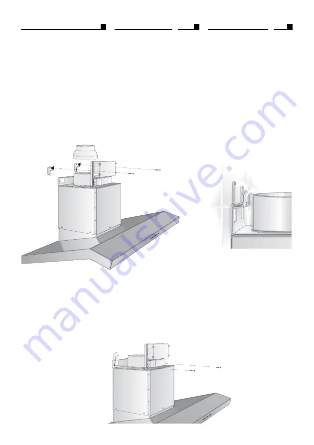
Fig. 6
Fig. 4
3.4 - INSTALLATION
A - POSITIONNEMENT HOTTE
- Monter le raccord de réduction 120/
150 si le tuyau d’évacuation air est
de Ø125.(Fig.4)
- Fixer les 2 crochets hotte à la paroi.
(Fig. 4)
- Suspendre solidement le corps de
la hotte au mur, en tenant toujours
compte que la distance entre le plan
de cuisson et le dessous de la hotte
ne doit pas être inférieure à 65 cm,
en utilisant les deux vis en dotation
M5 x 40 (Fig.5-6).
- Mettre la hotte à niveau en opérant
sur les vis (Fig. 4A)
B
– MONTAGE TUYAU EVACUATION
EXTERNE
- Utiliser de préférence un tuyau de
Ø150 ou Ø125, si possible, et l’arrê-
ter avec un collier de serrage au
raccord de réduction (Fig 7).
- Relier le tuyau d’évacuation à la
conduite externe et le fixer avec une
bande serre-tuyau.
3.4 - INSTALLATION
A - HOW TO POSITION THE HOOD
- Mount the 120/150 reduction fitting
whenever the air discharge tube is
Ø125.(Fig.4)
- Fix the 2 hood hooks to the wall (Fig.
4)
- Hang the hood case firmly to the
wall by means of the two M5 x 40
screws included in the supply and
remember that the cook top must
be of at least 65cm far from the lower
side of the hood (Fig. 5-6).
- Level the hood, working on the
screws (Fig. 4A)
B
- HOW TO ASSEMBLE THE OUT-
DOOR SCAVENGING PIPE
- Preferably use a Ø150 or Ø125 tube,
or possibly flexible, and fix it with a
hose clamp to the reduction fitting
(Fig 7).
- Connect the scavenging pipe to the
outdoor duct and fix it with a pipe-
tightening ring.
3.4 - INSTALLAZIONE
A - POSIZIONAMENTO CAPPA
- Montare il raccordo di riduzione
120/150 qualora il tubo di scarico
aria fosse di Ø125.(Fig.4)
- Fissare alla parete i 2 agganci cap-
pa. (Fig. 4)
- Appendere saldamente alla pare-
te il corpo cappa, tenendo sempre
presente che la distanza fra il pia-
no di cottura ed il sotto della cappa
non deve essere inferiore a 65 cm.,
utilizzando le 2 viti in dotazione M5
x 40 (Fig.5-6).
- Livellare la cappa agendo sulle viti
(Fig. 4A)
B - MONTAGGIO TUBO EVACUAZIONE
ESTERNA
- Utilizzare preferibilmente un tubo
Ø150 oppure Ø125, possibilmente
flessibile, e fermarlo con una
fascetta stringitubo al raccordo di
riduzione (Fig 7).
- Collegare il tubo di evacuazione
alla condotta esterna e fissarlo con
una fascetta stringitubo.
Fig. 4A


