Page
10
of
13
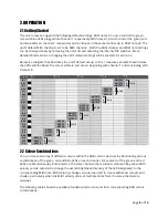
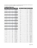
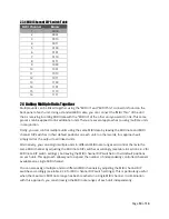
2.3.4 MIDI Channel DIP Switch Table
MIDI Channel
Binary
1
0000
2
0001
3
0010
4
0011
5
0100
6
0101
7
0110
8
0111
9
1000
10
1001
11
1010
12
1011
13
1100
14
1101
15
1110
16
1111
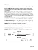
2.4 Linking Multiple Units Together
Multiple units can be linked together using the
“
MIDI In
”
and
“
MIDI Thru
”
connectors found on the
back panel of each unit. Using a standard MIDI cable, you can connect the
“
MIDI Thru
”
of the unit
that is receiving incoming MIDI data with the
“
MIDI In
”
of the other unit you want to link. This same
process can be applied to link additional units. There are several approaches to using multiple units
in conjunction.
Firstly, you can control multiple units using the same MIDI data by leaving the MIDI note and MIDI
channel DIP switches in their default positions on each unit. In other words, this approach will
simply mirror the output to all linked units.
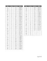
Alternatively, you can assign multiple units to different MIDI note ranges and control them via the
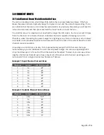
same MIDI channel by adjusting the MIDI note DIP switches accordingly (see table in section 2.3.2 for
MIDI note DIP switch settings), but leaving the MIDI channel DIP switches in their default positions
on each unit. This approach allows you to expand the number of independently controlled channels
available on a single MIDI channel.
You can also assign multiple units to different MIDI channels by adjusting the MIDI channel DIP
switches accordingly (see table 2.3.4 for MIDI channel DIP switch settings). This is particularly useful
when the maximum MIDI note range has been reached on a single MIDI channel. In combination
with this approach, you can still assign the MIDI note ranges of each unit independently.


