Page
5
of
13
2.0 OPERATION
2.1 Getting Started
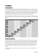
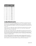
The unit comes set-up with the following default settings: MIDI notes 0, 1 and 2 control the green,
red, and blue LEDs plugged into channel 1 respectively, MIDI notes 3, 4 and 5 control the green, red
and blue LEDs on channel 2 respectively and continues in the same manner up to MIDI note 23. The
unit’s
default MIDI channel is set to be MIDI channel 1. Both the MIDI channel and MIDI note settings
can be changed easily by removing the
unit’s
lid and adjusting the internal DIP switches. More
detailed information on changing the unit’s default settings will be covered in section 2.2.
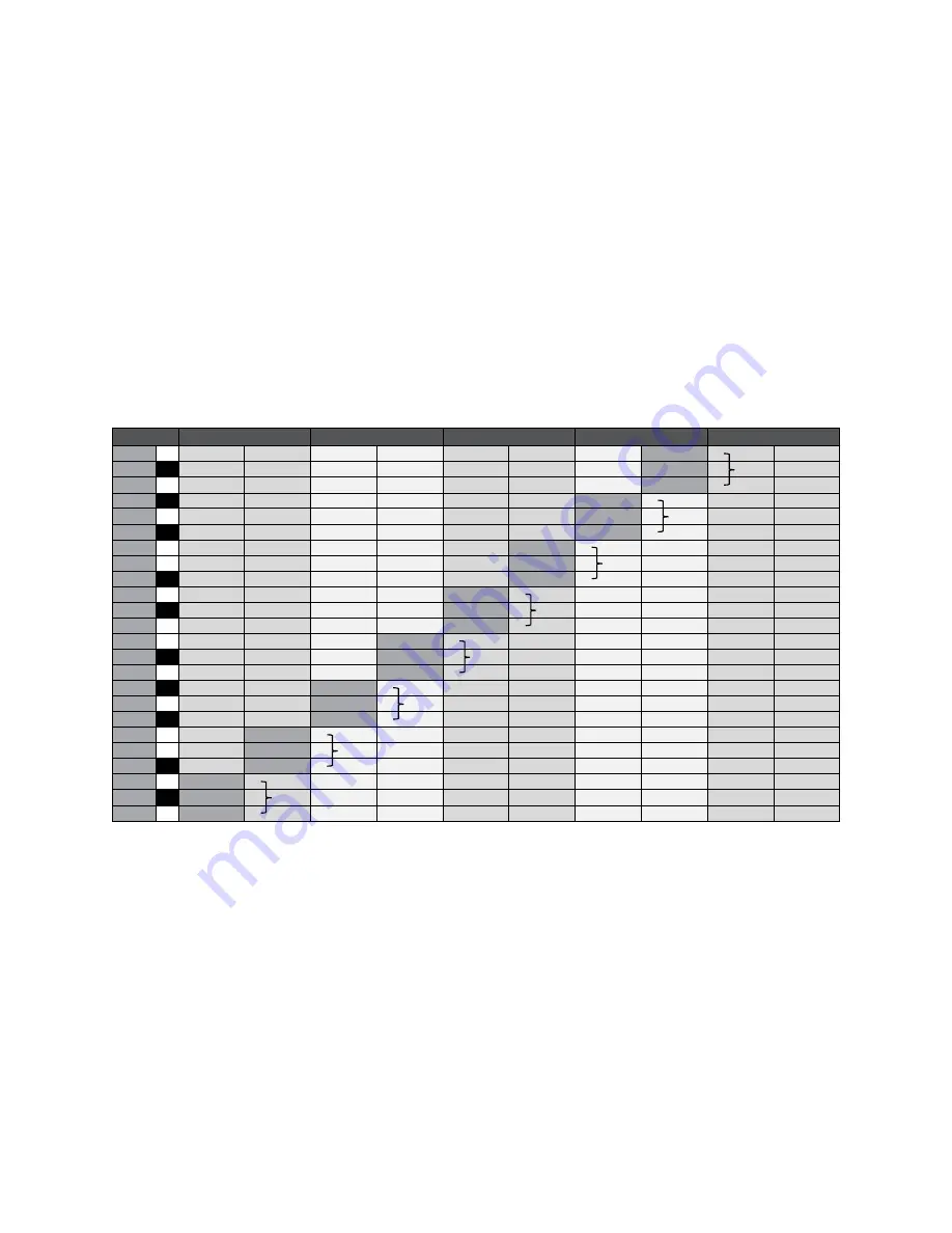
Below is a diagram that illustrates the
unit’s
default set-up. In the 1 measure example shown below,
the LEDs will illuminate the colour white in succession beginning with channel 1 and concluding with
channel 8.
4 / 4
1
1.2
1.3
1.4
2
B-1
NOTE 23
B
A#-1
NOTE 22
R CH 8
A-1
NOTE 21
G
G#-1
NOTE 20
B
G-1
NOTE 19
R CH 7
F#-1
NOTE 18
G
F-1
NOTE 17
B
E-1
NOTE 16
R CH 6
D#-1
NOTE 15
G
D-1
NOTE 14
B
C#-1
NOTE 13
R CH 5
C-1
NOTE 12
G
B-2
NOTE 11
B
A#-2
NOTE 10
R CH 4
A-2
NOTE 9
G
G#-2
NOTE 8
B
G-2
NOTE 7
R CH 3
F#-2
NOTE 6
G
F-2
NOTE 5
B
E-2
NOTE 4
R CH 2
D#-2
NOTE 3
G
D-2
NOTE 2
B
C#-2
NOTE 1
R CH 1
C-2
NOTE 0
G
2.2 Colour Combinations
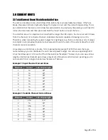
You can create an array of different colours within the RGB colour spectrum by illuminating various
combinations of the green, red and blue LEDs on each channel. For example, if the green and red
LEDs are simultaneously illuminated on the same channel, the resultant colour will be yellow. MIDI
velocity can be adjusted to change the overall brightness/intensity of the LED designated to the
corresponding MIDI note. MIDI velocity changes can also be used to create additional colours and
shades, particularly when the MIDI velocity value of multiple notes from the same channel are
unequal.
The following table shows the available fundamental colours and their corresponding RGB colour
combinations.


