background image

13

UM – P&ID Ancillaries Symbols Meaning

LV

Level Valve

M

Motor

TI

Temperature Indicator

LI

Level Indicator

PAH

Pressure Alarm High

TAH

Temperature Alarm High

PI

Pressure Indicator

PAHH

Pressure Alarm High Above PAH

TAHH

Temperature Alarm High Above TAH

FQ

Flow Indicator Totaliser

PSH

Pressure Switch High

TSH

Temperature Switch High

FAL

Flow Alarm Low

PSHH

Pressure Switch High Above PSH

TSHH

Temperature Switch High Above TSH

FSL

Minimum Flow Switch

PSV

Pressure Safety Valve

SUPPLY LIMIT

CANNON BONO

CUSTOMER

Summary of Contents for Cannon UNI-MATIC UM 100

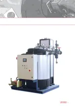
Page 1: ...FLASH COIL STEAM GENERATORS UNI MATIC Technical Book Steam Generators UM...

Page 2: ...Specifications 4 P ID 5 Dimensions and Connections 6 Generator Layout 7 Installation 8 Maintenance 9 Scope of Supply 10 Appendix 1 Fuel consumption calculation 11 Appendix 2 Thermodynamic characterist...

Page 3: ...3...

Page 4: ...units complete with all necessary equipment and ready to be connected to site utilities As optional an air preheater can be purchased additionally to the steam generator Preheater enables the boiler t...

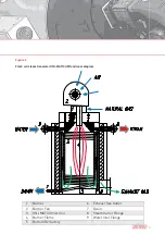
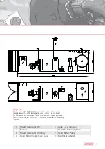
Page 5: ...6 Exhaust Gas Outlet 2 Burner Fan 7 Drain 3 UNI MATIC Inner Coil 8 Steam Outlet Flange 4 Burner Flame 9 Water Inlet Flange 5 Bottom Refractory Figure 3 Flash coil steam Generator UNI MATIC UM function...

Page 6: ...g types on off regulation of gas fuel feeding to the burner burner air vent and feeding water pump Liquid fuel supply to burner nozzle is achieved through electromagnetic opening closing valve two sta...

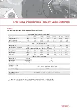
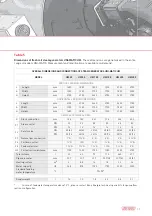
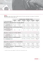
Page 7: ...sel oil KW 2 3 2 3 4 6 5 9 7 0 12 0 FUEL CONSUMPTION AT 100 OF THE LOAD Heavy fuel oil Kg h 21 1 35 1 70 3 105 4 140 6 210 9 Natural gas Nm3 h 24 1 40 1 80 2 120 3 160 4 240 6 Diesel oil kg h 20 1 33...

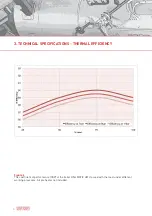
Page 8: ...3 TECHNICAL SPECIFICATIONS THERMAL EFFICIENCY Figure 6 The coefficient of performance COP of the boiler UNI MATIC UM crossed with the load under different working pressures Air preheater not included...

Page 9: ...9 Figure 7 A plot of the coefficient of performance COP of the boiler UNI MATIC UM with air preheater...

Page 10: ...bottom of the tank but slightly higher to avoid the entry of impurities If the oxygen scavenger is required please refer to the technical specifications of the product in use Total hardness Less than...

Page 11: ...ponents under the conditions of boiler operation are difficul to predict Organic substances may be decomposed to form carbonic acid or other acidic decomposition products which increase the acid condu...

Page 12: ...t Pipe QE Electrical Cabinet V2 Brine Tank C5 Steam to User Pipe D1 Instrument Header V3 Chemical Dosing Station F1 Feed Fuel Pipe D2 Steam Separator C1 Condensate Return Pipe P10 Feed Water Pump C2 F...

Page 13: ...h PI Pressure Indicator PAHH Pressure Alarm High Above PAH TAHH Temperature Alarm High Above TAH FQ Flow Indicator Totaliser PSH Pressure Switch High TSH Temperature Switch High FAL Flow Alarm Low PSH...

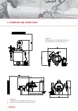
Page 14: ...5 DIMENSIONS AND CONNECTIONS Figure 10 Steam generator UNI MATIC UM Horizontal version steam generator overall dimensions Figure 9 Steam generator UNI MATIC UM vertical steam generator overall dimensi...

Page 15: ...100 2385 GENERAL TECHNICAL DATA D Stack connection mm 125 162 263 314 346 400 F1 Steam outlet DN 32 32 50 50 65 80 PN 16 16 16 16 16 16 F2 Safety valve DN 20 40 20 40 20 40 25 40 25 40 32 50 PN 25 16...

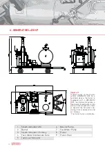
Page 16: ...wo feed water pumps a feed water condensate return tank a booster pump to create a head for the hot waters de riving from condensation and a chimney The trailer hook is orientable 1 Steam Generator UM...

Page 17: ...rical cabinet mounted on the container s wall one feed water pump a feed water condensate return tank a chimney and a water softening system 1 Steam Generator UM 5 Tank Level Indicator 2 Burner 6 Wate...

Page 18: ...cabinet mounted on the generator one feed water pump a feed water condensate return tank a chimney and a water softening system 1 Steam Generator UM 5 Tank Level Indicator 2 Burner 6 Water Softening S...

Page 19: ...190 M tc GAS 9 P M tc Minimum gas pressure at train mbar 50 50 50 50 60 100 Riello burners diesel oil 1 or 2 stages regulation Riello type RL 34 1 tc RS 38 tc RL 100 tc RL 130 tc RL 190 tc PRESS 300 P...

Page 20: ...r inlets one of which as close to the fan as pos sible The boiler room must be high enough for the coil to be taken out Connections to be made Make the following connections to start the generator Chi...

Page 21: ...e up water softened by a purifier cation resin or demineralised The water supply must always come from the supply tank a direct connection to the mains water or to the purifier is not allowed The suct...

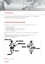
Page 22: ...s also a humidity separator In this regard kindly refer to the relevant para graph During normal functioning of the generator the steam produced passes through the manifold The manifold is thus very h...

Page 23: ...ctrical system For the connection lead the three phase line to the control panel and connect it to the terminals of the main switch checking the direction of rotation of the motors If the electrical b...

Page 24: ...indications of Figure 15 2 The terminal of the drainage piping must be placed in a protected and difficult to reach position so that the steam can exit freely without causing damage to people or thin...

Page 25: ...el Check naphtha pre heater temperature Check operation of supply water tank float level regulator Check water supply pump oil level Monthly operations Clean water supply pump suction filter Clean bur...

Page 26: ...on In a separate container prepare a 10 water and caustic soda solution 9 parts water and 1 part caustic soda Pour the solution inside the generator through the burner hole and fill up to 5 cm from th...

Page 27: ...he coil with respect to the plating inside Replace the front cover sealing gaskets Assemble the stub pipes packing the conical threads with a little teflon tape and tighten completely Put new smoke se...

Page 28: ...Inhib Lithsolvent L Content solvay soda kg UM 30 100 80 11 0 50 3 UM 50 150 120 16 0 75 4 UM 100 200 160 22 1 6 UM150 UM 200 300 200 30 1 5 10 UM 300 500 300 40 2 15 Important in order to operate in s...

Page 29: ...only for vertical design Steam pressure gauge complete with cock 1 pc 1 pc 1 pc 1 pc 1 pc 1 pc Steam temperature thermometer 1 pc 1 pc 1 pc 1 pc 1 pc 1 pc Sight glass for water filling indication 1 pc...

Page 30: ...pc 1 pc 1 pc 1 pc 1 pc 1 pc High efficiency combustion air fan 1 pc 1 pc 1 pc 1 pc 1 pc 1 pc Electric type ignition device with high tension and ignition electrodes only for fluid fuel 1 pc 1 pc 1 pc...

Page 31: ...r feed water circu lation 1 pc 1 pc 1 pc 1 pc 1 pc 1 pc ELECTRIC WIRING With flexible conduits and tight terminal fittings for high mechanical resistance and water proof sealing 1 pc 1 pc 1 pc 1 pc 1...

Page 32: ...accessories 1 pc 1 pc 1 pc 1 pc 1 pc 1 pc HIGH TEMPERATURE FEED WATER PUMP Feed water pump to reach temperature above 95 C 1 pc 1 pc 1 pc 1 pc 1 pc 1 pc SECOND SAFETY VALVE Second safety valve 1 pc 1...

Page 33: ...Values regarding enthalpy are taken from Appendix 2 As calorific power of natural gas is 8500 kcal Nm3 we determine hg enthalpy of saturated steam under 9 bar gauge pressure and he enthalpy under 70...

Page 34: ...0 306 1 313 1 339 380 55 107 4 1 312 450 5 107 6 2238 7 534 7 2689 2 642 3 0 40 0 408 1 413 1 441 382 65 109 5 1 225 459 7 109 8 2232 8 533 3 2692 5 643 1 0 50 0 510 1 513 1 543 384 75 111 6 1 149 468...

Page 35: ...5 50 5 608 6 513 6 641 435 25 162 1 0 292 685 0 163 6 2077 1 496 1 2762 0 659 7 6 00 6 118 7 013 7 151 438 15 165 0 0 272 697 9 166 7 2067 4 493 8 2765 4 660 5 6 50 6 628 7 513 7 661 440 95 167 8 0 2...

Page 36: ...ented in this technical book are indicative and subject of changing due to product customization and innovation processes They must be considered by the user only at the first stage of product selecti...

Reviews: