


19 / 64
IOM Manual VF-W_ATEXgb - Translation of original instructions in Italian - Rev 03_0 - 30/09/16
Installing ATEX-specified gearboxes
• Category 2D gearboxes must be installed in compliance with the provisions of standards EN 1127-1, EN
61241-14 and EN 61241-17. Installation technicians must be fully qualified to work in potentially explosive
atmospheres.
• Installation technicians must be aware of the ATEX classification of the installation area, must understand
the risks associated with potentially explosive atmospheres with particular reference to explosion and fire
hazards, and must adopt all necessary safety precautions.
• All maintenance, assembly and disassembly work must be done
by specialist personnel outside the
explosion hazard area.
• Check that all accessory components (cables, joints, cable clamps, heat exchangers, etc.) also comply
with the requirements of the ATEX directive. Handle all components with extreme care to avoid altering
their characteristics.
• Remove the sealing bolts from the threaded holes needed to install the gearbox. Take care not to damage
the mating surfaces.
• When installing gearboxes with reaction arms, make sure that no sliding movement is generated between
metallic parts when the gearbox is functioning. If necessary, fit non-metallic anti-friction elements
conforming to Directive 2014/34/EU between moving metal parts.
• Do not connect any object with an electrical resistance greater than 10
9
Ω to the gearbox.
• Install guards to prevent hazardous accumulations of dust and liquids at the seals of protruding shafts and
to protect them mechanically.
• The gearbox input speed (or the speed of the motor coupled to it) must not exceed n
1
=1500 min
-1
.
• When installing a gearmotor with the electric motor arranged vertically with its shaft facing down, the
motor must be covered by a protective canopy.
• The output shaft and any pulleys or other transmission components must be perfectly aligned.
• Only install the gearbox with the motor version and in the mounting position specified in the order. Shaft-
mounted gearboxes can be installed with a tolerance of ± 5° to the theoretical plane of installation.
• If the gearbox is supplied without lubricant it must be installed as it is and only filled with lubricant on
completion of installation.
• Secure the gearbox to a flat, vibration-free surface capable of bearing the torsional stresses it produces in
service. Take care not to deform mating surfaces, mounting feet or flanges by over-tightening fixing bolts.
• Use bolts graded no lower than 8.8 for mounting the gearbox. For heavy duty installations 10.9 grade
bolts can be used. Do not use bolts graded higher than 8.8 to install gearboxes with mounting elements
(casing, flange or foot) made from aluminium. See the “INSTALLING THE GEARBOX” section in this
manual for tightening torque values. To stop mounting bolts becoming loose, apply Loctite 510 (or a
product with similar properties and application range) to the threads of all bolts securing the gearbox to
the machine structure and to the electric motor, also apply it to the threads of all the oil plugs (even on
those eventually removed for oil level check, before their relocation).
• Make sure that overhung and thrust loads and operating torques do not exceed those for which the
gearbox is specified.
• Make sure that the vent plugs and oil level plugs are easy to access for inspection.
• Clean the gearbox thoroughly after installation.
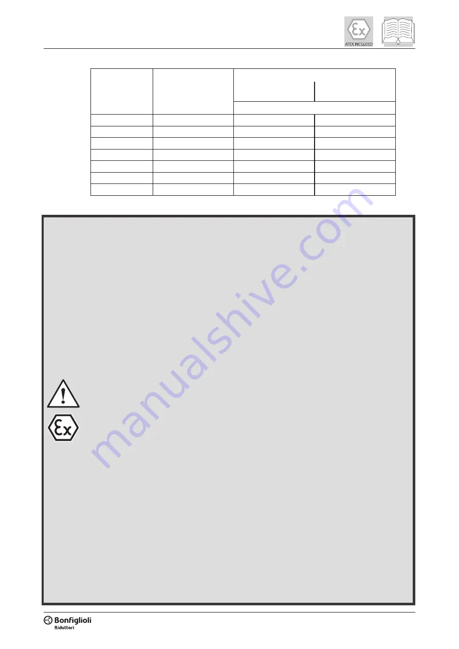
(tab 2)
Plug/vent thread
Pitch (threads per inch)
Tightening torque [Nm]
Plugs with non-metallic
gasket
Plugs with aluminum
or copper gasket
+5%/-5%
1/8”
28
5
10
1/4”
19
7
10
3/8”
19
7
20
1/2”
14
14
30
3/4”
14
14
40
1”
11
25
40
M14x2
2 [mm]
20
—


