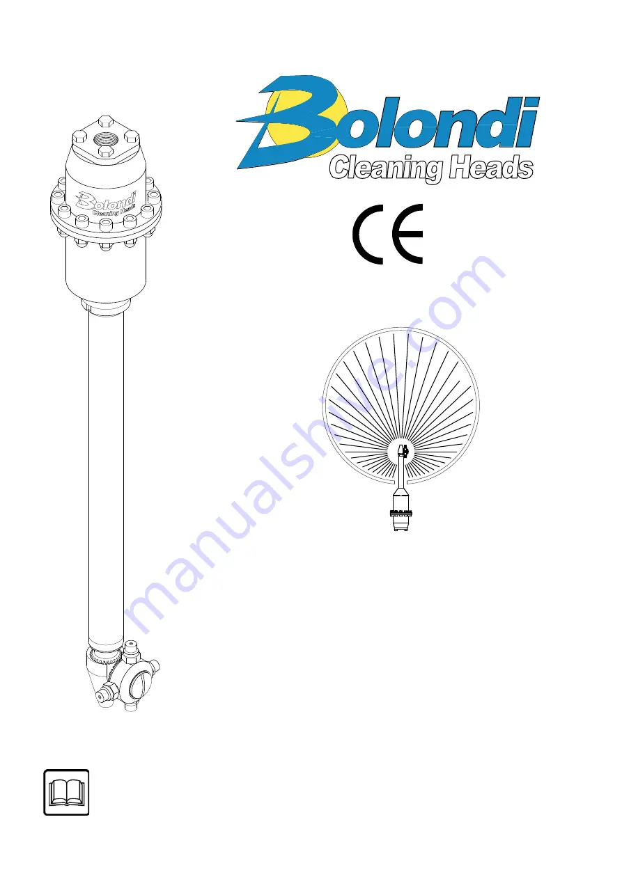
OPERATING AND MAINTENANCE
MANUAL HEADS mod. XC 061-AAM.0
4
XC 061-AAM.02-MANUAL Rev.03
SERIAL N°:
18241334
WARNING:
THIS MANUAL IS AN INTEGRAL PART OF THE MACHINE AND
MUST BE READ AND KEPT FOR REFERENCE.
Translation of the original instructions
Page 1: ...TENANCE MANUAL HEADS mod XC 061 AAM 04 XC 061 AAM 02 MANUAL Rev 03 SERIAL N 18241334 WARNING THIS MANUAL IS AN INTEGRAL PART OF THE MACHINE AND MUST BE READ AND KEPT FOR REFERENCE Translation of the original instructions ...
Page 2: ...ITIONS AND LIMITS OF USE pag 6 4 GENERAL SAFETY STANDARDS pag 7 5 TECHNICAL SPECIFICATIONS pag 8 9 6 DIAGRAM OF THE ASSEMBLY pag 10 7 INSTALLATION AND COMMISSIONING pag 10 11 8 INDICATIVE CHOICE OF THE DIFFUSER AND NOZZLE BASED ON THE FLOW RATE pag 12 9 MAINTENANCE pag 13 21 10 SPARE PARTS pag 22 TABLE B TORQUE WRENCH SETTINGS pag 22 REGISTRATION OF JOBS DONE NOTE pag 23 25 EXPLODED VIEW pag 26 SP...
Page 3: ...7 of appendix I of machinery directive 2006 42 EC The applicable essential safety requirements of directive 97 23 EC pressurised equipment classified in art 3 cat 3 It also complies with the following harmonised European standards UNI EN 14121 2009 Risk Assessment Principles UNI EN ISO 12100 2010 Safety of machinery General principles for design The undersigned also declares that the incomplete ma...
Page 4: ...elivery for EEC countries 1 year from the date of delivery for non EEC countries During this period the Manufacturer undertakes to repair or replace parts that present acknowledged construction defects free of charge excluding transport and labour costs which are entirely at the expense of the purchaser 3 The warranty does not cover all parts that are subject to wear parts that have been damaged d...
Page 5: ...aterial damage resulting from the non observance of the indications that accompany the symbol The symbol represents a safety warning Failure to follow the instructions given can cause serious personal injury N B for accident prevention purposes the equipment must be fitted with suitable devices to prevent automatic re starting when the equipment is powered after a shut down The head must not be us...
Page 6: ...re recyclable secondary raw materials and must be given to the relevant authorised collection centres Plastics Recycling Allowed where carried out Dispose of in dumps for waste assimilable to urban waste Incineration Allowed in plants equipped with post combustion and a system to eliminate dust before being let into the atmosphere 02 000 00 EN 3 CONDITIONS AND LIMITS OF USE 3 1 Never point the jet...
Page 7: ... pressure and flow rate of pump 4 7 Install a relief cock 1 that is as near the water inlet 2 as possible when the head is in use but always remains on the outside and is easily accessed by the operator Fig 4 0 4 8 The cock should be normally closed and the head should only be started inside the container to be washed and with the container properly closed 4 9 The screw connections of all the flex...
Page 8: ...LET 1 2 FILTER 700 MICRON NUMBER OF NOZZLES 2 4 NOZZLES 1 8 NPT O RING NBR EPDM VITON SEALS PTFE CARBON FIBRE BUSHING AISI 316 MATERIAL AISI 316 MIN CENTER LINE THROUGH HOLE 95 mm MAX MANUAL THROUGH HOLE 76 mm EXTERNAL HOSE LENGTH ON REQUEST XXXX mm DIFFUSER SEE CHART A ROTATION SPEED 22 28 RPM FULL CYCLE 31 ROTATIONS FULL CYCLE TIME 1 3 MIN A 24 RPM WEIGHT Kg 3 5 ...
Page 9: ...NZE GENERALI classe m UNI EN 22768 1 6 30 0 2 XX XX XX file XC 061 AAM cm DESCRIZIONE RUGOSITA 3 2 UNI 4600 1 6 SGROSS FINITURA GREZZO 0 1 NOTE 0 6 DATA FOGLIO MODIFICA 120 400 XC 061 AAM 01 APPLICATION DRAWING 0 3 30 120 XXXX 0 5 1 2 3 CLEANING HEADS MONTECCHIO E RE ITALY 07 05 08 1000 2000 1 2 DISEGN SCALA DATA 1 4 CR 4 5 CONTR A4 DM 0 MOD ...
Page 10: ...mended to purge it to eliminate any sludge or impurities Breakages or problems caused by soiling will not be accepted under warranty On the head inlet install a safety valve set at the maximum pressure shown on its mark or at page 8 of this manual 7 1 Put the head 1 in the container to be washed 7 2 Secure the head to the container via the fl ange 2 Contact the manufacturer for special flanges Fig...
Page 11: ...he chemical specifications of the fluids used 7 6 Make sure the technical specifications flow rate and pressure of the head page 8 are compatible with the specifications of the pump installed on the system 7 7 Only in these conditions is the head in the ideal working position simultaneously having all the necessary safety requirements 7 8 The head is set for the specifications indicated on page 8 ...
Page 12: ...0 DF0420 Upon consignment the head is built as requested in the order placed If the flow rate and pressure vary replace the diffuser pos 33 and the nozzle pos 55 to ensure optimum operation From table A choose the most suitable diffuser pos 33 for the new parameters Before you make any changes you are recommended to contact the manufacturer Follow the procedure given in the maintenance manual to r...
Page 13: ...apter refer to the spare parts ex ploded diagram on page 26 NB For all the tightening jobs with dynamometric spanner refer to the table B on page 22 9 1 Cleaning the inlet filter pos 63 Disassembly 9 1 1 Unscrew and remove the screws pos 57 disassemble the filter holder flange pos 62 and remove the cartridge pos 63 Fig 9 0 9 1 2 Clean the cartridge pos 63 thoroughly make sure there are no breakage...
Page 14: ...crew the screws pos 57 using a dynamometric spanner 9 2 Replacing the diffuser pos 33 Disassembly 9 2 1 Disassemble the inlet filter as explained in section 9 1 1 9 2 2 Using a 5 mm hex spanner and a 10 mm ring spanner unscrew the twelve screws and the twelve nuts pos 57 and pos 58 see fig 9 2 9 2 3 Take the top casing pos 1 off and push the diffuser kit pos 33 out fig 9 3 then replace after selec...
Page 15: ...fig 9 4 9 2 6 Position the top casing and secure it with the twelve screws pos 57 and the nuts pos 58 using a dynamometric spanner 9 2 7 Fit the inlet filter back in place as explained in section 9 1 3 to 9 1 5 9 3 Replacing the seals pos 82 on the nozzle holder crown pos 84 Disassembly 9 3 1 Clamp the head in a bench vice and using a suitable screwdriver unscrew and remove the screw pos 86 and th...
Page 16: ...fitted correctly in its seat and lubricate with silicone grease type KLUBER PARALIQ GTE 703 9 3 6 Insert the following on the pin pos 80 in the given sequence the nozzle holder crown pos 84 the washer pos 85 the tightening screw pos 86 Put some Loctite 222 on the thread of the screw pos 86 and tighten with a suitable screwdriver 9 4 Replacing the seals pos 52 on the pinion pos 72 Disassembly 9 4 1...
Page 17: ...ig 9 12 ZB0031 Kit D 18 Kit D 45 43 44 Kit C 45 Fig 9 13 A 9 4 3 Using the spanner supplied ZB0031 unscrew and disassemble the output shaft Kit D the bearing unit pos 43 44 45 Fig 9 11 9 12 9 4 4 Slide the complete internal rod out A fig 9 13 ...
Page 18: ...ing a blunt tool To make it easier to insert the ring follow the instructions in fig 9 8 page 16 9 4 8 Make sure everything is fitted correctly in its seat and lubricate with silicone grease type KLUBER PARALIQ GTE 703 9 4 9 Put a few drops of Loctite 572 on the thread of the pinion pos 72 screw onto the external hose pos 71 and tighten with a 22 mm fixed jaw spanner ATTENTION LEFT HAND SCREW THRE...
Page 19: ...te 222 on the thread of the output shaft pos 18 Kit D screw the same onto the internal rod and tighten with the special spanner supplied ZB0031 and check with dynamometer fig 9 16 9 4 13 Fit as explained in section 9 3 6 Fig 9 16 ZB0031 Kit D 18 Kit D Loctite 222 ...
Page 20: ...pos 38 to release the clamp ring nut pos 67 then move this away from the casing pos 40 Fig 9 17 c Unscrew the bottom casing pos 40 until the end part and output shaft are unable to turn d Slowly screw the bottom casing pos 40 again until there is approximately 0 1mm between the pinion pos 72 and the pin pos 80 check with gauge fig 9 18 Fig 9 18 80 72 0 1 Fig 9 17 39 67 40 38 58 ...
Page 21: ...our gears pos 10 kit F2 on the output shaft pos 18 kit D 9 4 17 In the following sequence fit the washer pos 8 the planetary holder pos 15 kit E1 and the four planetary gears pos 32 kit F1 repeat the sequence for the next stage insert ing the second washer pos 8 the planetary holder pos 13 kit E and the three planetary gears pos 29 kit F 9 4 18 Place the washer pos 5 on the crown pos 31 Make sure ...
Page 22: ...ts tables when choosing spare parts Spare parts should be requested by fax to following address Bolondi Via A Volta 4 42027 MONTECCHIO RE ITALY Tel 39 0522 864434 Fax 39 0522 865780 e mail bolondi bolondi com always indicate the model and serial number of the head see identification plate the code and description of the part ordered see table the quantity required the preferred means of shipment 1...
Page 23: ...E REGISTRATION OF JOBS DONE Date Description of failure Description of the job Result Operator s segnature 13 000 00 E REGISTRATION OF JOBS DONE Date Description of failure Description of the job Result Operator s segnature 13 000 00 E ...
Page 24: ...E REGISTRATION OF JOBS DONE Date Description of failure Description of the job Result Operator s segnature 13 000 00 E REGISTRATION OF JOBS DONE Date Description of failure Description of the job Result Operator s segnature 13 000 00 E ...
Page 25: ...E REGISTRATION OF JOBS DONE Date Description of failure Description of the job Result Operator s segnature 13 000 00 E REGISTRATION OF JOBS DONE Date Description of failure Description of the job Result Operator s segnature 13 000 00 E ...
Page 26: ... 58 71 52 72 74 80 84 86 85 82 82 91 Vedi see F1 Vedi see F Vedi see F2 Vedi See I Vedi See G Vedi see E1 Vedi see E Vedi see D Vedi see C Vedi See B Vedi see A Vedi See L 68 70 69 39 67 38 58 MODELLO XC 061 AAD_AAM LP DISEGN Versione R NOTE VIA VOLTA 4 TEL 39 522 864434 FAX 39 522 865780 ITALY Data 01 09 2010 E Mail bolondi bolondi com MONTECCHIO E RE 03 ...
Page 27: ...XC 061 AAM 02 MANUAL Rev 03 27 ...
Page 28: ...XC 061 AAM 02 MANUAL Rev 03 28 Via A Volta 4 Tel 0522 864434 Fax 865780 42027 MONTECCHIO E Reggio E Italy E mail bolondi bolondi com Web site http www bolondi com ...