background image

21

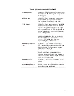
Table 9, High Pass/Low Pass Parameters

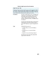
High Pass (Low Cut)

This feature helps eliminate low frequency noise (signals of 100 Hz 

and below, such as background rumble from ventilation systems, 

etc.) and is used primarily with microphone level input. It is partic-

ularly effective when hand held microphones are used.

Frequency

Set the cutoff frequency. You can adjust the 

frequencies by moving the knob or by dou-

ble-clicking the knob and typing the fre-

quency. When typing the frequency, only 

numeric values from 20 Hz to 20,000 Hz can 

be entered.

The high pass filter attenuates content below 

this frequency and lets frequencies above 

this cutoff frequency to pass through the fil-

ter.

Type

Available filter types are:
• Linkwitz-Riley (12, 24, and 36 dB per 

Octave)

• Butterworth (12, 18, and 24 dB per 

Octave)

• Bessel (12, 18, and 24 dB per Octave)
The filter type name and the selected dB 

appear above the knob.

Summary of Contents for Nyquist NQ-A2060

Page 1: ...2 Channel Audio Power Amplifiers Configuration Manual NQ A2060 NQ A2120 NQ A2300 2019 Bogen Communications Inc All rights reserved 740 00084E 191030 ...

Page 2: ......

Page 3: ... Parameters 13 6 1 Setting the Channel Level 15 6 2 Signal LED Clip LED and VU Meter 16 6 3 Muting a Channel 16 6 4 Adjusting Volume Levels 16 6 5 Adjusting Compression Settings 17 6 6 Adjusting the Graphic Equalizer 18 6 7 Setting High Low Pass Parameters 20 6 8 Adjusting the Limiter 23 6 9 Adjusting Noise Gate Settings 24 6 10 Adjusting Parametric Equalizer Settings 25 6 11 Adjusting Router Sett...

Page 4: ...ii ...

Page 5: ...e 14 Figure 9 Compressor Settings 17 Figure 10 Graphic EQ Settings 19 Figure 11 High Low Pass Parameters 20 Figure 12 Limiter Settings 23 Figure 13 Noise Gate Settings 24 Figure 14 Parametric Equalizer Settings 25 Figure 15 Router 27 Figure 16 Router for Single Channel Bridged Mode 27 Figure 17 Settings Parameters for 2 Channel Mono 28 Figure 18 Settings Parameters for Single Channel Bridged 29 Fi...

Page 6: ...vi ...

Page 7: ...Network Settings 6 Table 4 Configuration Settings 9 Table 5 Device Stations Settings 10 Table 6 Logs 12 Table 7 DSP Page 15 Table 8 Compressor Settings 18 Table 9 High Pass Low Pass Parameters 21 Table 10 Limiter Settings 23 Table 11 Noise Gate Settings 25 Table 12 Signal Present Parameters 31 Table 13 Status 33 ...

Page 8: ...viii ...

Page 9: ...solution A short press of the appliance s Reset button reboots the device If you press the Reset button for 10 seconds the appliance returns to the factory default configuration settings Returning to the default configuration settings does not change the appliance s firmware The following sections describe the process for manual configuration For information about using Nyquist s automatic configu...

Page 10: ...At the Nyquist Appliance Login page enter username and password and then select Login The default username is admin the default password is bogen The dashboard for the selected appliance appears Figure 1 Nyquist Appliance Login Figure 2 Matrix Mixer Pre Amp Dashboard ...

Page 11: ...ons Dashboard Refreshes the dashboard Configuration Set tings Accesses the Configuration Settings page where you can either manually set various options such as the SIP Username or select to receive configuration settings from the server Network Settings Accesses the Network Settings page where you can view and set network settings such as the static IP address Firmware Update Accesses the Firmwar...

Page 12: ...e Nyquist Matrix Mixer Pre Amp Configuration Manual Logout Logs out of the appliance s dashboard Table 2 Appliance Dashboard Buttons Note A Nyquist appliance connected to the Nyquist network receives a config uration file from the Nyquist server that includes the latest firmware available from the server If the firmware is later than the one installed on the appliance an automatic firmware update ...

Page 13: ...are version the Firmware Update page displays an Update Firmware button Select this button if you want to update the appliance s firmware to the new version Step 3 If you want to return your appliance to its original state undoing firmware updates select Restore Factory Settings Step 4 Select Reboot Appliance to restart your appliance 3 Setting Network Tab Parameters Network settings can be config...

Page 14: ...IP Identifies the fixed IP address assigned to the appliance by a system administra tor Netmask Identifies the subnetwork subdivision of an IP network Gateway Identifies the address or route for the default gateway VLAN ID Identifies the Virtual Local Area Network VLAN for this appliance Values range from 0 to 4094 ...

Page 15: ...t 69 the stan dard TFTP port Device provisioning files are stored on the Nyquist server in directory srv tftp This is the only directory exposed by the TFTP server DHCP Server Over ride Indicates if you want to override the TFTP server information provided by the Dynamic Host Configuration Protocol DHCP via option_66 DHCP supplies IP addresses to the Nyquist server and associated devices It also s...

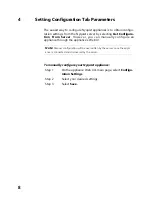
Page 16: ...rom Server However you can manually configure an appliance through the appliance s Web UI To manually configure your Nyquist appliance Step 1 On the appliance Web UI s main page select Configu ration Settings Step 2 Select your desired settings Step 3 Select Save Note Manual configuration will be overwritten by the server once the appli ance is connected and discovered by the server ...

Page 17: ...on Settings Table 4 Configuration Settings Web Username Provide a web username for this appliance Web Password Provide a web password for logging into the appliance Web Confirm Pass word Re enter the password used to log into the appliance Server Identifies the IP address of the Nyquist server ...

Page 18: ...ntifies the IP address port number and volume used for all calls pages Audio Distribution Identifies the IP address port number and volume used for audio distribution Multicast Identifies the multicast IP address for a zone that the speaker is included in If a speaker is added to multiple zones the multicast IP address for each zone appears Table 5 Device Stations Settings Port Number Identifies t...

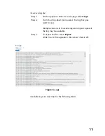
Page 19: ... drop down menu select the log that you want to view Multiple versions of the same log and zipped copies of the log may be available Step 3 To export the file select Export A link to a txt file appears in the screen s lower left Available logs are described in the following table Figure 6 Logs ...

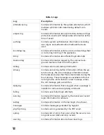
Page 20: ...d debug information dmesg Contains kernel ring buffer information When the sys tem boots up the screen displays information about the hardware devices that the kernel detects during the boot process These messages are available in the ker nel ring buffer and whenever a new message comes the old message gets overwritten dpkg log Contains information that is logged when a package is installed or rem...

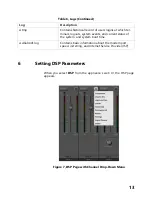
Page 21: ...al record of users logins at which ter minals logouts system events and current status of the system and system boot time wvdialconf log Contains basic information about the modem port speed init string and Internet Service Provider ISP Table 6 Logs Continued Log Description Figure 7 DSP Page with Channel Drop Down Menu ...

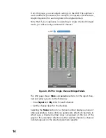
Page 22: ...ute and Level selections for the input chan nels and allows you to do the following View Signal and Clip LEDs for each channel Set the channel level for the channels Selecting the Menu button for a channel number displays a menu of other parameters Some of these parameters affect all channels in which case a channel number does not appear on the top of the graphic If a parameter affects only the s...

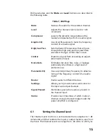
Page 23: ...frequency content of an audio signal High Low Pass Sets the band of frequencies that will pass through the high pass and low pass filters and select the type of filter that is used Limiter Prevents a signal from exceeding an adjust able maximum level Noise Gate Eliminates low level hiss noise or leakage particularly when there is a high level of ambient noise Parametric EQ Uses a center primary fr...

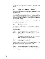
Page 24: ...ng on the signal level but also has a scale ranging from 60 to 0 to help you indicate the actual signal level 6 3 Muting a Channel You can mute a channel to cut off an audio signal and stop the pro duction of sound To mute a channel Step 1 On the appliance Web UI s main page select DSP Step 2 Select the Mute button for the channel that you want to silence The Mute button will illuminate red You ca...

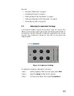
Page 25: ...ynamic range of a signal This effect is perceived to quiet loud sounds and boost quiet sounds A compressor smooths transients Compressor parameters are set per channel The Compressor dialog box has LEDs for the input and output signals To adjust the compressor settings for a channel Step 1 On the appliance Web UI s main page select DSP Step 2 Select the Menu button for the channel Step 3 From the ...

Page 26: ...rcuit The range is 135 to 21 dB Attack Sets how fast the compressor turns on when the audio signal passes the threshold level The range is 1 to 500 ms Hold Sets how long the compressor is on after the signal has fallen below the threshold The range is 1 to 500 ms Decay Sets the rate of turn off of the compressor after the signal is below the threshold he range is 0 to 2000 ms Knee Sets how the com...

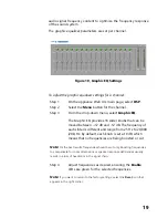
Page 27: ...nd 12 dB The frequency of each slider is different and range from 25 Hz to 20 000 20k Hz By default each knob is set at 0 dB which means that no frequencies are being boosted or cut Step 4 Adjust frequencies as desired ensuring the Enable LEDs are green for the selected frequencies Figure 10 Graphic EQ Settings Note For the best results frequencies should be cut only Boosting frequencies to compen...

Page 28: ...own menu option To adjust the high low pass parameters for a channel Step 1 On the appliance Web UI s main page select DSP Step 2 Select the Menu button for the channel Step 3 From the drop down menu select High Low Pass Step 4 Set the parameters described in the following table Figure 11 High Low Pass Parameters Note If you want to return to the factory settings select the Reset icon that appears...

Page 29: ...y You can adjust the frequencies by moving the knob or by dou ble clicking the knob and typing the fre quency When typing the frequency only numeric values from 20 Hz to 20 000 Hz can be entered The high pass filter attenuates content below this frequency and lets frequencies above this cutoff frequency to pass through the fil ter Type Available filter types are Linkwitz Riley 12 24 and 36 dB per ...

Page 30: ...larly effective when hand held microphones are used Frequency Set the cutoff frequency You can adjust the frequencies by moving the knob or by dou ble clicking the knob and typing the fre quency When typing the frequency only numeric values from 20 to 20 000 can be entered The low pass filter attenuates content above this frequency and lets frequencies below this cutoff level to pass through the f...

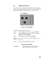
Page 31: ...ep 1 On the appliance Web UI s main page select DSP Step 2 Select the Menu button for the channel or select the Menu button for the Output Step 3 From the drop down menu select Limiter Step 4 Adjust the following settings as needed Figure 12 Limiter Settings Note If you want to return to the factory settings select the Reset icon that appears in the right corner Table 10 Limiter Settings Threshold...

Page 32: ...elect the Menu button for the channel Step 3 From the drop down menu select Noise Gate Decay Sets the rate for turn off of the limiter after the signal is below the threshold Decay range is 5 to 2300 milliseconds RMSTC Sets how fast the limiter reacts to the above threshold signal RMSTC range is 50 to 10000 Figure 13 Noise Gate Settings Note If you want to return to the factory settings select the...

Page 33: ...ignal must be below for the noise gate to close pre vent the sound from getting through Threshold range is 135 to 21 db Attack Adjusts how long it takes for the gate to open once the signal falls below the thresh old Attack range is 1 to 500 ms Hold Defines the length of time the gate will stay fully open after the signal falls below the threshold Hold range is 1 to 500 ms Decay Sets the rate for ...

Page 34: ...red Step 5 Make desired Q adjustments by adjusting knob or double clicking and typing the desired adjustment Q can be from 0 1 to 20 and sets how wide to either side of the selected frequency the adjacent frequencies are affected Q is the Quality or Quality Factor which refers to the bandwidth of one band of a parametric equalizer Q is calculated by dividing the center frequency in Hz by the width...

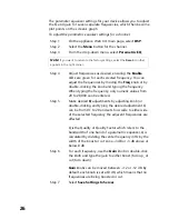
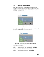
Page 35: ...and only want to route the signal to the first speaker If your appliance is configure for single channel bridged mode only one output channel appears on the Router screen To adjust the router settings Step 1 On the appliance Web UI s main page select DSP Step 2 Select the Menu button for the channel Step 3 From the drop down menu select Router Figure 15 Router Figure 16 Router for Single Channel B...

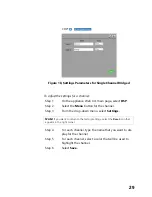
Page 36: ...output 6 12 Settings You can set select names and colors for each of the input channels Note that if your appliance is configured for single channel bridge mode only one Network input channel appears Figure 17 Settings Parameters for 2 Channel Mono ...

Page 37: ...n menu select Settings Step 4 For each channel type the name that you want to dis play for the channel Step 5 For each channel select a color that will be used to highlight the channel Step 6 Select Save Figure 18 Settings Parameters for Single Channel Bridged Note If you want to return to the factory settings select the Reset icon that appears in the right corner ...

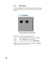
Page 38: ...t channel To adjust the Signal Present settings for a channel Step 1 On the appliance Web UI s main page select DSP Step 2 Select the Menu button for the channel Step 3 From the drop down menu select Signal Present Figure 19 Signal Present Parameters Note If you want to return to the factory settings select the Reset icon that appears in the right corner ...

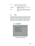
Page 39: ...for ther mal protection and clipping and a real time ready of the appliance s temperature Note that if your appliance is configured for single channel bridge mode only one Network input channel appears Table 12 Signal Present Parameters Threshold Sets the threshold level or at what level the Signal LED is illuminated Hold Sets the number of milliseconds that the sig nal light stays on after the si...

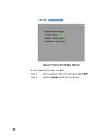
Page 40: ...32 To view status for the power amplifier Step 1 On the appliance Web UI s main page select DSP Step 2 Select the Menu button for the channel Figure 21 Status for Bridged Channel ...

Page 41: ...needed For information about setting the Amplifier Mode refer to the installation manual for the appliance Thermal Protect Appears red if the equipment has become too hot and has placed itself into protection mode Otherwise the LED is green Channel 1 Output Limit Appears red if the output signal is being clipped or distorted Otherwise the LED is green Channel 2 Output Limit Appears red if the outp...

Page 42: ...34 ...

Reviews: